

Elite Industries EL-785, EL-745 Assembly Instructions Manual
J8
5/8" Screws for
attaching G1
K4
1" Screws for
middle hole
to attach G2
L2
Door Handle
H4
2"
Machine Screws
for Door Handle
Hardware for door assembly
Page 1/4 2.11.08
PLEASE DO NOT RETURN UNIT TO STORE FOR PARTS & CUSTOMER SERVICE.
PLEASE CALL 1-800-ELITE-48. CUSTOMER SERVICE HOURS EASTERN TIME 8:45 AM - 4:45 PM M-F
VISIT OUR WEBSITE AT:
www.elite-inds.com
Thank you for purchasing this Elite product. You will need the following tools:
Phillips Head Screw Driver • Straight Blade Screw Driver • Rubber Padded Hammer or Mallet
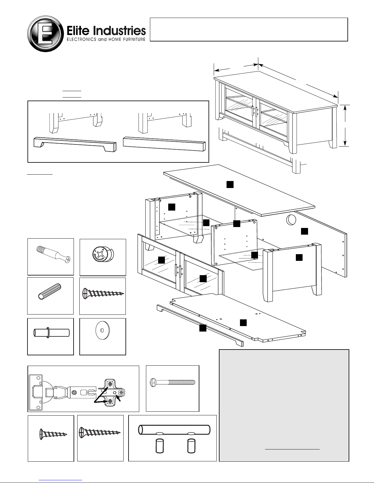
47"
1
5
3
2
6
6
9
9
7
8
4
Hardware for unit assembly
P
ARTS
1. Top Panel
2. Bottom Panel
3. Left Side Panel
4. Right Side Panel
5. Vertical Divider Panel
6. Glass Adjustable Shelf (2 identical)
7. Back Panel
8. Bottom Front Rail
9. Glass Door with Wooden Frame (2 identical)
F8
Plastic Covers
for Camlocks
C12
Wooden
Dowels
D11
1" Screws for
Back Panel
E8
Shelf Pins
A16
Connecting
Bolts
B16
Camlocks
IMPORTANT NOTES & CAUTIONS/WARNINGS
• Carefully read and follow these instructions for assembly.
• Please handle parts carefully, some parts may be heavy and can
have sharp edges – we recommend possibly using cloth protective gloves for extra protection.
• To protect the unit and your flooring surface we recommend working on a padded or carpeted area, you may also use the open box
the unit came in for this purpose.
• For proper construction & integrity/assembly and for TV weight
support and safety, all connections need to be sufficiently tight.
However, do not over-tighten connections to the point of stripping
screw threadings. Parts are designed to fit together tightly, however, avoid excessive force but rather align & fit panels together
methodically and with patience.
• For some heavy or large units, it may be recommended for 2 people to work together on this assembly.
• It is extremely important to attach the BACK PANEL as instructed
within this manual. Such panels are crucial for the stability and
structural support of the unit.
• Please read additional important safety information at the end of
this instruction manual.
•We urge you to keep this manual with your unit for future reference.
18
1
/
2"
20
3
/
4"
G4
G1
G2
Hinge Pairs G1 + G2
G1 is attached to Door.
G2 is attached to Side Panel.
HOLE FOR
SCREW K
2 FACTORY
INSTALLED SCREWS
Assembly Instructions
47" WIDE TV STAND, AUDIO/VIDEO COMBINATION UNIT
OVERALL DIMENSIONS: 20
3
/4" H x 47" W x 18 1/2" D
EL-785: Oak Veneer (shaped leg & rail)
EL-745: Wenge (straight leg & rail)
NOTE: Assembly instructions for both the EL-785 and the EL-745 are the same. The shape of the
leg on Side Panels (3, 4) and the shape of the Bottom Front Rail (8) are the only differences.
EL-785
EL-745
EL-785 OAK VENEER
Shaped Leg, Shaped Rail
EL-745 WENGE
Straight Leg, Straight Rail

1 TOP PANEL PREPARATION
Page 2/4 2.11.08
Place Top Panel (1) on padded surface
with underside up. Insert 6 Connecting
Bolts (A) as shown. NOTE: Holes for
Connecting Bolts have factory installed
threaded bushings.
3 BOTTOM FRONT RAIL PREPARATION
Insert 4 Connecting Bolts (A) into back
of Bottom Front Rail (8) as shown.
UNDERSIDE
FRONT EDGE
A
A
A
A
1
8
2 VERTICAL DIVIDER PANEL PREPARATION
Insert 2 Camlocks (B) and
2 Wooden Dowels (C) into
top edge of Vertical Divider
Panel (5) as shown.
Insert 2 Camlocks (B) and
2 Wooden Dowels (C) into
bottom edge of Vertical
Divider Panel (5) as shown.
See Camlock/Connecting
Bolt Procedure below.
4 BOTTOM PANEL PREPARATION
C
C
C
G2
C
C
C
B
B
B
5
FRONT EDGE
UNDERSIDE
B
C
C
C
C
2
FRONT EDGE
A
2
DO NO T
INSERT
CONNECTING
BOLT
FURTHER
THAN DEPTH
SHOWN.
DO NO T
INSERT
CONNECTING
BOLT
FURTHER
THAN DEPTH
SHOWN.
Turn Bottom Panel (2)
over so that top side is up.
Insert 2 Connecting Bolts (A) into indicated holes with
factory installed threaded bushings as shown.
A
K
K
4
FRONT EDGE
BACK
EDGE
NOTE
GROOVE
FOR
BACK
PANEL (7)
Please note in the diagram at the right, the characteristics
of the front and back edges of the side panels.
A. Insert 2 Dowels (C) into outer holes
in top edge of RightSide Panel (4).
B. Insert 2 Camlocks (B) into top of Right
Side Panel (4) as shown.
C. Insert 2 Connecting Bolts (A) into smaller, outer holes
on bottom of Right Side Panel (4) as indicated.
D. Attach a G2 part of Hinge unit using 1" long screw K
to the top front portion of the inner brace. Attach another
G2 part of Hinge unit using 1" long screw K to the
bottom front portion of the inner brace. 1 screw K goes
into the center hole of each part G2 as shown.
After tightening screw K, tighten 2 factory installed
screws of G2.
Repeat steps A through D for the Left Side Panel (3).
Attach Door Handle (L) to Door
(9) using 2 Machine Screws (H).
Thread each screw through
back of door and short door
posts into long handle portion of
Door Handle (L).
Repeat for
second Door.
Attach G1 portion
of Hinge unit to
inside upper and
lower portions of
Door (9) using 4
short Screws (J).
Repeat for second
Door.
H
G1
G1
L
J
J
9
9
Place Bottom
Panel (2) on
padded surface
with underside up.
Insert 8 Camlocks (B) as
shown. Insert 2 Dowels (C)
into each edge as shown
6 DOOR PREPARATION
5 RIGHT AND LEFT SIDE PANEL PREPARATION
CAMLOCK
CONNECTING BOLT
PROCEDURE
Be sure
to insert
Camlocks
with the small
arrow facing
the edge.
Align
Connecting
Bolt with
Camlock and
join pieces
together.
Turn Camlock
180° clockwise
to lock. The
long curved
ar
row will now
be on the
edge.
 Loading...