

Page 1

Page 2

Preface
Copyright 2012
All Rights Reserved.
The information in this document is subject to change without prior
notice in order to improve reliability, design and function and does not
represent a commitment on the part of the manufacturer.
In no event will the manufacturer be liable for direct, indirect, special,
incidental, or consequential damages arising out of the use or inability
to use the product or documentation, even if advised of the possibility
of such damages.
This document contains proprietary information protected by
copyright. All rights are reserved. No part of this manual may be
reproduced by any mechanical, electronic, or other means in any form
without prior written permission of the manufacturer.
Limitation of Liability
While reasonable efforts have been made to ensure the accuracy of
this manual, the manufacturer and distributor assume no liability
resulting from errors or omissions in this manual, or from the use of
the information contained herein.
Conventions of This Manual
Use this manual will help you get the most from your computer.
If you are an experienced user of computers and/or Microsoft’s
Windows operating systems, you might find it useful to read the
Quick Start Guide that comes along with your accessories.
If you are a less experienced user, you should go through th e manual
carefully before using your system.
Whether or not you are an experienced user, you should consult the
Troubleshooting Chapter if you encounter any problems with your
computer.
i
Page 3

Safety Precautions
This section is designed to assist you in identifying potentially un safe
conditions while working with this product. Required safety features
have been installed in the computer to protect you from injury.
However, you should use good judgment to identify po tential safety
hazards:
Please read these safety instructions carefully.
1. Please keep this User's Manual for later reference.
2. Please disconnect this equipment from AC outlet before cleaning.
Don't use liquid or sprayed detergent for cleaning. Use moisture
sheet or cloth for cleaning.
3. For pluggable equipment, that the socket-outlet shall be installed
near the equipment and shall be easily accessible.
4. Please keep this equipment from humidity.
5. Lay this equipment on a reliable surface when installed. A drop
or fall could cause injury.
6. Make sure to use the right voltage for the power source when
connecting the equipment to the power outlet.
7. Place the power cord in such a way that people can not step on it.
Do not place anything on top of the power cord.
8. All cautions and warnings on the equipment shoul d be not ed.
9. If the equipment is not used for a long time, disconnect the
equipment from the main power outlet to avoid being damaged
by transient overvoltage.
10. Never pour any liquid into the opening, this could cause fire or
electrical shock.
11. Never open the equipment. For safety reasons, the equipment
should only be opened by a qualified service pers o nnel .
12. If on the following situation arises, get the equipment checked by
a service personnel:
a. The Power cord or plug is damaged.
b. Liquid has penetrated into the equipment.
c. The equipment has been exposed to moisture.
d. The equipment has not worked well or you cannot get it
work according to the user's manual.
e. The equipment has dropped and damaged.
f. If the equipment has obvious signs of breakage.
13. Do not leave this equipment in an environment unconditioned,
storage temperature above 60C (140f), it may damage the
equipment.
ii
Page 4

14. The unit can be operated at an ambient temperature of max. 5C
~ 35C.
15. The sound pressure level of the operator's position according to
IEC 704-1: 1982 is equal or less than 70 dB(A).
16. Power Cord Requirements
The power cord set used with the AC adaptor must meet the
requirements of the country where you use the AC adaptor,
whether it is 100-240 Vac. The following information explains
the requirements for power cord set selection.
The cor
it is used.
The appliance coupler must have a configuration for
mating with a CEE7/EN60320/IEC 320/NEMA/ JIS C
8303 appliance inlet.
d set must be approved by the country in which
A. For U.S. and Canada:
The cord set must be UL Listed and CSA Certified.
The minimum specifications for the flexible cord are
No. 18 AWG, (2) Type SPT-2, and (3) 2-conductor.
B. For Japan:
All components of the cord set must bear a “PSE” mark
and in accordance with the Japanese Dentori Law.
The minimum specifications for the flexible cord
are .75m ㎡ conductors, (2) Type VCTR or VCTFK,
and (3) 2-conductor.
The cord set must have minimum rated current capacity
of 7 A.
The attachment plug must be a two-pole, grounded type
with a Japanese Industrial Standard C8303 (15 A, 125
VAC) configuration.
C. For Other Countries:
The cord set fittings must bear the certification mark of
the agency responsible for evaluation in a specific
country.
The flexible cord must be of a HAR (harmonized) type
H03VVH2-F.
The cord set must have a current capacity of a least 2.5
Amperes and voltage rating of 125 or 250 Vac.
iii
Page 5

Model: BR95IIX (X=0~9) IS
designed to use with the following AC adapter model
ONLY 65W ADP:
Delta type: ADP 19V65W DELTAADP-65JH AB S1
225RV LV5
Lite-On type: ADP 19V65W LITEONPA-1650-65 S1
225RV LV5
17. When using your telephone equipment, basic safety precautions
should always be followed to reduce the risk of fire, electric
shock and injury to persons. These precautions include the
following:
Do not use this product near wa ter, for example, near a
bathtub, washbowl, kitchen sink or laundry tub, in a wet
basement or near a swimming pool.
Avoid using a telephone (other than a cordless type)
during an electrical storm. There may be a remote risk of
electric shock from lightning.
Do not use the telephone to report a gas leak in the
vicinity of the leak.
Use only the power cord and batteries indicated in this
manual. Do not dispose of batteries in a fire. They may
explode. Check with local codes for possible special
instructions.
18. Do not use the AC adapter near open water or other liquids.
Never spill liquid into the AC adapter.
19. Danger of explosion if battery is incorrectly replaced. Replace
only with the same or equivalent type recommended by the
manufacturer. Dispose of used batteries accordi n g to the
manufacturer's instructions. Never rem ove t he battery pack
while the power is on as this may result in data loss when the
system loses power.
20. The input receptacle is used as the main disconnecting device.
This part is hot. Be careful.
Diese Flachewird sehr heiss.
When you see this symbol, be careful as this spot may be
very hot.
21. Laser Warning: Laser Class I Product Caution - Invisible laser
radiation when open avoid exposure to beam.
The optical drive used with this computer is certified as a
iv
Page 6

Class1 laser device according to the U.S. Department of Health
and Human Services (DHHS) Radiation Performance Standard
and International Standards IEC 60825-1 (EN60825-1). The
device is not considered harmful, but the following precautions
are recommended:
Do not open the unit.
Avoid direct exposure to the laser beam.
If the unit requires service, cont act an au thoriz ed serv ice
center.
Ensure proper use by reading and following the
instructions carefully.
Do not attempt to make any adjustment of the unit.
Class 1 Laser Product
Appareil A Laser De Classe 1
Laserschutzklasse 1 Produkt
Do not attempt to disassemble
the cabinet containing the laser. The laser beam used in
this product is harmful to the eyes. The use of optical
instruments, such as magnifying lenses, with this product
increase the potential hazard to your eyes. For your safety,
have this equipment serviced only by an authorized
service provider.
Mesures de sécurité
Cette section a pour but de vous aider à identifier des conditions
potentiellement dangereuses d'utilisation de ce matériel. Les
dispositifs de sécurité nécessaires ont été installés sur l'ordinateur pour
vous protéger contre d'éventuelles blessures. Cependant, vous devez
utilisez votre propre discernement pour identifier les dangers possibles:
1. Veuillez lire ces instructions attentivement.
2. Veuillez conserver le présent guide d'utilisation pour référence
ultérieure.
3. Veuillez débrancher ce matériel de l'alimentation secteur avant
nettoyage. N'utilisez pas de détergent liquide ou vaporisé pour le
nettoyage. Utilisez un tissu humidifié.
4. En ce qui concerne le matériel connecté, veillez à ce que la prise
d'alimentation soit située à proximité du matériel et facilement
accessible.
5. Veuillez conserver ce matériel à l'abri de l'humidité.
6. Installez ce matériel sur une surface stable. Une chute peut
v
Page 7

provoquer des blessures.
7. Vérifiez que vous utilisez une tension d'alimentation correcte
avant de brancher l'adaptateur secteur.
8. Placez le cordon d'alimentation de manière à ce que personne ne
puisse marcher dessus. Ne placez aucun objet sur le cordon
d'alimentation.
9. Tous les avis et avertissements concernant ce matériel doivent
être respectés.
10. Si le matériel n'est pas utilisé pendant une longue période,
débranchez-le de l'alimentation secteur afin d'éviter qu'il puisse
être endommagé par d'éventuelles surtensions.
11. Ne jamais verser de liquide dans les ouvertures, cela pourra i t
provoquer un incendie ou un choc électrique.
12. N'ouvrez jamais le boîtier. Pour des raisons de sécurité, le
matériel ne doit être ouvert que par un technicien spécialisé.
13. Si l'une des situations suivantes est rencontrée, faites vérifier le
matériel par un technicien de maintenance :
Le cordon d'alimentation est endommagé.
Du liquide a pénétré dans l'appareil.
Le matériel a été exposé à l'humidité.
Le matériel ne fonctionne pas correctement, ou vous ne
pouvez pas le faire fonctionner comme indiqué dans le
guide d'utilisation.
Le matériel est tombé et il est abîmé.
Le matériel présente des signes évidents de rupture.
14. Ne laissez pas ce matériel dans un environnement non contrôlé.
Des températures de plus de 60° Celsius (140° F) peuvent
endommager le matériel.
15. Le système peut être utilisé dans une température ambiante
maximale de 5C ~ 35C.
16. Le niveau sonore au niveau de l'utilisateur, selon les termes de la
norme IEC 704-1: 1982 est inférieur ou égal à 70 dB(A).
17. Conditions nécessaires pour le cordon d'alimentation
Le cordon d'alimentation utilisé avec l'adaptateur secteur doit
respecter les conditions fixées pour le pays dans lequel vous
utilisez l'adaptateur secteur, qu'il s'agisse d'un courant alternatif
100-240 volts. Vous trouverez ci-dessous les informations
concernant les exigences appliquées au jeu de cordon
d'alimentation.
Le jeu de cordon doit être homologué pour le pays dans
lequel il est utilisé.
vi
Page 8

Le coupleur du matériel doit être compatible avec une
prise de type CEE7/EN60320/IEC 320/NEMA/ JIS C
8303.
A. Pour les États-Unis et le Canada :
Le jeu de cordon doit être énuméré dans la liste UL et
certifié CSA.
Les caractéristiques minimales pour le cordon flexible
sont No. 18 AWG, (2) Conducteur du type SPT-2, et (3)
2.
B. Pour le Japon :
Tous les éléments du jeu de cordon doivent comporter
le numéro d'enregistrement selon la loi japonaise
Dentori.
Les caractéristiques minimales pour le cordon flexible
sont des conducteurs de type 0.75mm², (2) Conducteur
du type VCTF ou VCTFK, et (3) 2.
Le cordon doit avoir une capacité de courant nominal
minimum de 7A
La fiche de branchement doit être du type deux pôles et
mise à la terre avec une configuration de standard
industriel japonais C8303 (15A, 125 VAC)
C. Pour les autres pays :
Les raccords du jeu de cordon doivent porter la marque
de l'agence responsable de l'évaluation dans un pays
déterminé.
Le cordon flexible doit être de type HAR (harmonisé)
H03VVH2-F.
Le jeu de cordon doit avoir une capacité d'au moins 2,5
et accepter une tension de 125 ou 250 volts.
Le modèle BR95IIX (X=0~9) est
conçu pour être utilisé uniquement avec le modèle
d'adaptateur CA suivant
Delta type: ADP 19V65W DELTAADP-65JH AB S1
225RV LV5
Lite-On type: ADP 19V65W LITEONPA-1650-65 S1
225RV LV5
18. Lors de l'utilisation de votre matériel téléphonique, des mesures
de précaution élémentaires doivent être respectées afin de
minimiser les risques de feu, de choc électrique et de blessure.
Ces mesures sont énumérées ci-dessous :
vii
Page 9

N'utilisez pas ce matériel à proximité de l'eau, comme
par exemple près d'une baignoire, d'un lavabo, d'un bac
à laver, dans un sous-sol humide ou près d'une piscine.
Évitez d'utiliser le téléphone (autre qu'un téléphone
portable) pendant un orage. Il peut exister un risque de
choc électrique.
N'utilisez pas le téléphone pour signaler une fuite de
gaz à proximité de la fuite.
Utilisez uniquement le cordon d’alimentation et les
batteries spécifiés dans ce manuel. Ne jetez pas les
batteries au feu. Elles pourraient exploser. Reportezvous à la règlementation locale pour d'éventuelles
instructions particulières.
19. N'utilisez pas l'adaptateur secteur à proximité d'une étendue d'eau
ou d'autre liquide. Ne versez pas de liquide dans l' adapt a te ur
secteur.
20. Avertissement relatif aux produits Laser de classe I : Des
radiations invisibles sont émises par le Laser. Evitez de vous
exposer à ces radiations lorsque le tiroir est ouvert.
21. Risque d’explosion si la batterie est remplacée d’une manière
incorrecte. Remplacez uniquement avec une batterie de même
type ou de type équivalent recommandée par le constructeur.
Débarrassez-vous des batteries usagées en accord avec les
instructions du constructeur. Ne jamais retirer le bloc de batteries
lorsque l’alimentation est en marche car cela risque de provoquer
une perte de données liée à la perte d’alimentation.
Class 1 Laser Product
Appareil A Laser De Classe 1
Laserschutzklasse 1 Produkt
N’essayez pas de
démonter le boîtier contenant le laser. Le rayon laser
utilisé dans ce produit est dangereux pour les yeux.
L’utilisation d’instruments optiques, tels que des loupes,
avec ce produit augmente les dangers potentiels pour vos
yeux. Pour votre sécurité, faites réparer cet équipement
uniquement par un réparateur agréé.
En cas d'urgence, l'utilisateur arrête le système en
débranchant la prise d'alimentation.
viii
Page 10

Things you must remember before working on your
computer
Let your computer acclimate itself
Your computer can easily stand temperature extremes but it doesn’t
like rapid changes in temperature, like going from the cold outdoors to
a warm office.
Rapid changes in temperature can cause water droplets to condense
inside your case, threatening to damage the electronic parts inside.
After receiving your computer when it’s hot or cold outside, try not to
power up the computer immediately, let the computer adjust to the
room temperature gradually at least for three to four hours.
If your system arrives in cold
weather, do not apply power to the computer or monitor
until they have been allowed to come to room temperature.
Heat, Cold, Humidity, and Glare
Find a suitable place for your computer that’s not too hot,
too cold, too dark, or too bright. Glare can make it hard to
read the screen.
Try to avoid the computer compon ents from be ing
destroyed if it is overheated, so try to allow plenty of
room for air to circulate around the case.
Do not block the ventilation opening.
Do not place your computer in direct sunlight.
Suitable place to work
Your computer will run well wherever you’re comfortable but
extreme temperature and humidity can be challenging to your
system’s parts.
There are some things you can tolerate that the computer can’t –
things like static electricity, dust, water, steam and oil. In case you
decide to pull over for roadside computing, try to choose a clean,
comfortable work area for your system.
A lithium-ion battery pack will be available when you are traveling. If
you are running your system for the first time on battery power,
remove the battery from the package, install it into the system and
recharge the battery to fully prepare for service.
ix
Page 11

Table of Conent
Introduction ----------------------------------------------------------------------- 12
Working Room Scenario ...................................................................... 12
Living Room Scenario .......................................................................... 13
Business Trip Scenario ......................................................................... 13
Getting Started ------------------------------------------------------------------- 18
Help Windows ...................................................................................... 20
Desktop ................................................................................................. 20
Recycle Bin .................................................................................. 21
Start Button .................................................................................. 21
Taskbar ......................................................................................... 21
Notification .................................................................................. 22
Using the Desktop Computer ----------------------------------------------- 2
LCD or CRT Monitor Connection ........................................................ 2
Keyboard and Mouse Connection ......................................................... 2
Expanding the System .......................................................................... 2
Printer Connection ................................................................................ 2
Speaker Connection .............................................................................. 2
Card Readers, Memory Cards Connection ........................................... 2
Internet Connection ------------------------------------------------------------ 5
Running BIOS Setup ----------------------------------------------------------- 7
Main Setup ............................................................................................ 9
Info Setup ............................................................................................. 9
Advanced .............................................................................................. 10
Security ................................................................................................. 10
TPM ...................................................................................................... 11
Boot Setup ............................................................................................ 11
Exit Setup ............................................................................................. 12
Finger Printer --------------------------------------------------------------------- 14
Troubleshooting ----------------------------------------------------------------- 23
Specification---------------------------------------------------------------------- 26
Detailed Specifications ------------------------------------------------------- 26
x
Page 12

11
Page 13

IInnttrroodduuccttiioonn
Welcome to the Desktop Computer
This computer is a small compact computer considered as a desktop
replacement considered using a bulky size on your table.
The system supports numerous connectors that allows you to connect
digital video camera, digital camera, hard disk, and other compatible
electronic appliances.
Scenarios in using your Desktop Computer
Working Room Scenario
In using this computer in your own private study room, place it
together with LCD monitor, speakers, printer/scanner/fax, or any other
peripherals.
12
Page 14
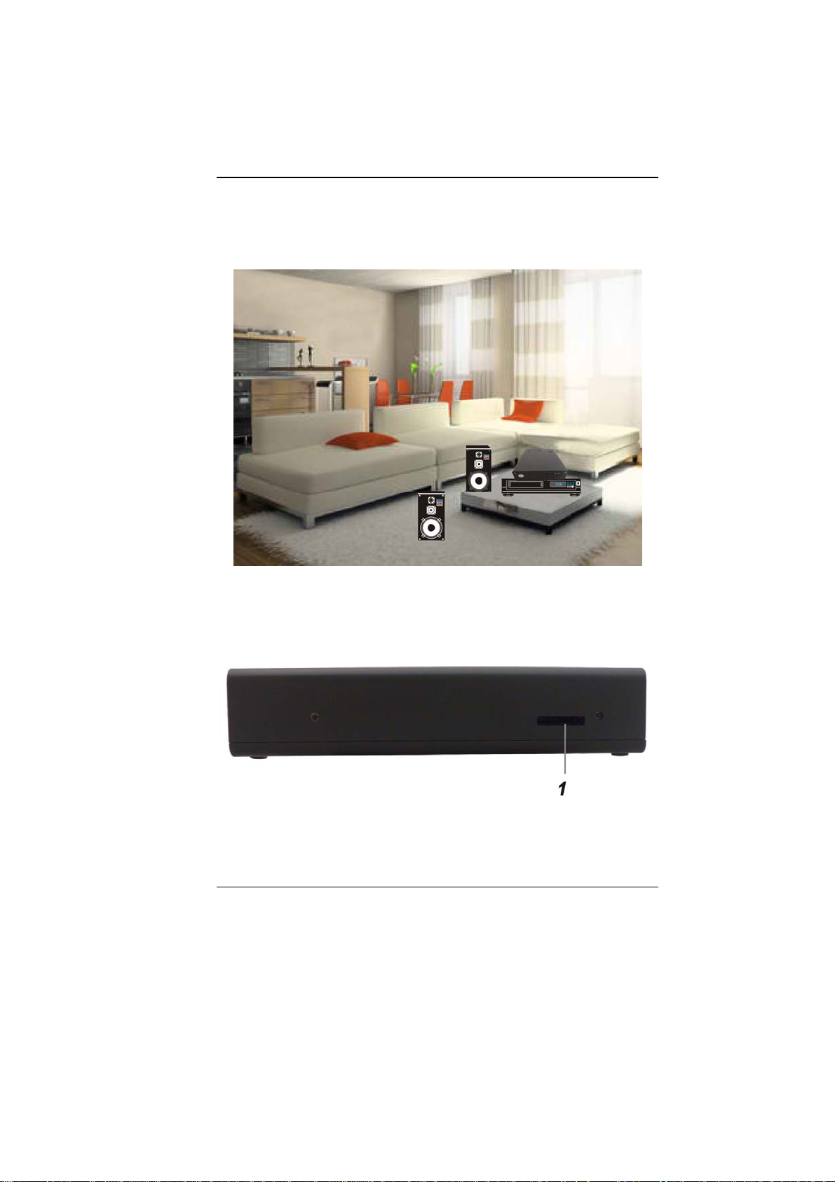
Living Room Scenario
In using the Desktop Computer in your own living room, connect it to
a speaker, DVD/VCD player, or any other peripherals in building your
own media center at home.
Business Trip Scenario
Because of being a handy computer, you can carry the pc with you on
your business trip since it can be conveniently keep in a hand bag.
Front Side Features
1. CardReader (SD/SDHC/SDXC(High speed
mode)/MMC/MS/MS-Pro)
13
Page 15
Be sure the face of the card must
be facing down when inserting without using the stand or
bottom side facing you when inserting using the stand.
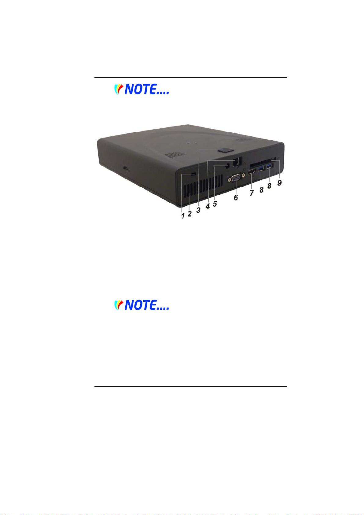
Rear Side Features
1. Kensington Security Slot
Attach a Kensington lock to this slot to secure your computer to a
fixed location.
2. Ventilation Opening
The ventilation opening allows the computer to cool off and
prevent overheating. Do not block t his opening when the
computer is turned on.
3. FingerPrinter
Fingerprint recognition or fingerprint authentication refers to the
automated method to identify individuals and verify their identity.
4. LAN Connector
When using a LAN, please use an
EMI Shielding Cable to minimize an inteference when
transmitting.
5. Power Jack (DC-in)
The DC-out jack of the AC Adapter connects here and power on
the computer.
6. External Monitor Port
Use this port to connect to an external monitor.
14
Page 16
7. HDMI Port
Compact audio/video interface for transmitting uncompressed
digital data.
8. USB 2.0 Ports
This port conforms to the latest USB2.0 plug-and-play standards.
9. ExpressCard Slot
Standard for higher speed PCMCIA form factor cards that
supports USB2 and PCI Express.
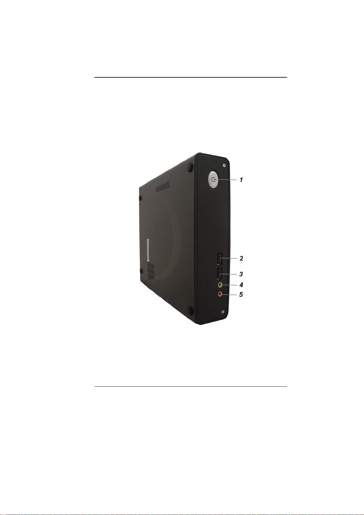
Top Side Features
1. Power/Suspend Button
Press momentarily to turn on the system.
Press the power/suspend button again to return from the suspend
mode.
2. USB 2.0 Port
This port conforms to the latest USB2.0 plug-and-play standards.
15
Page 17

3. USB 2.0 Port
This port conforms to the latest USB2.0 plug-and-play standards.
4. Stereo Headphone Jack
Use the headphone jack to connect an external headphone set.
5. Microphone Jack
Use the microphone jack to connect an external microphone.
16
Page 18

17
Page 19

GGeettttiinngg SSttaarrtteedd
Connecting to a Power Source
A universal AC adapter is provided to supply your computer with
power. The adapter’s AC input voltage can range anywhere from 100
to 240 volts, covering the standard voltages available in almost every
country. The power cord for the AC adapter requires a three-hole
grounded AC outlet. To connect the computer to an external power
source:
Do not use inferior extension
cords as this may result in damage to your computer. The
computer comes with its own AC adapter. Do not use a
different adapter to power the computer and other
electrical devices.
18
Page 20

Never turn off or reset or move
your comptuer while the hard disk is in use; doing so can
result in loss or destruction of your data. Always wait at
least 5 seconds after turning off your computer before
turning it back on; turning the power on and off in rapid
succession can damage the computer’s electrical circuitry.
Powering up the Desktop Computer
At the top of the desktop computer, locate on the power button and
press for a few seconds to power up the system. The Power-On Self
Test (POST) runs automatically.
After the POST is completed, the computer reads the operating system
from the hard disk drive into computer memory (this is commonly
referred to as “booting” a computer). If your OS (Operating System
such as Windows 7…. etc) is installed, it should start automatically.
To turn the computer off, save your work and close all open
applications, click on Start, then Shu
the computer and click "Y
seconds. (abnormal shutdown)
es" or press the power button for 4-6
t Down and select Shut down
19
Page 21

Using the Windows
Help Windows
For Windows 7 help,
click Start Help
and Support icon
will open the dialog
box.
Desktop
Desktop may vary differently on the software installed in your
computer with different or additional shortcuts.
20
Page 22

Recycle Bin
Used for storing deleted files in case you want to recover and save it
in your system. The files will only be deleted from the Recycle Bin
permanently only if you empty it by right clicking your mouse and
select the “Empty Recycle Bin”.
Start Button
Allows easy access to all Windows programs.
The Start menu allows you to adapt and show the programs used
most frequently. If you wish to keep an item, right click the item and
click Pin to Start menu.
Log Off will enable the current user to log off and allows a new user
to log on.
Turn Off Computer allows you to shut down, restart, and Stand by
modes for power saving purposes.
Taskbar
When you open a program, its icon is displayed at the taskba r for you
to conveniently move between programs by clicking the relevant
button.
To add or remove toolbars from the taskbar: right click an empty spot
on the taskbar, select Toolbars choose the toolbar you want to
21
Page 23

add.
Notification
The icons that appear here are for quick access to some programs and
computer functions that you frequently used. To prevent Windows 7
from hiding icons:
From an empty spot on the Taskbar, right click your mouse and
select the Properties, remove the checked mark on the Auto-hide the
taskbar.
Control Panel
It is in this area that you can change how Windows looks and works.
Click Start Control Panel dialog box. There are two interfaces –
Classic View.
22
Page 24

23
Page 25

Page 26

1
Page 27

UUssiinngg tthhee DDeesskkttoopp CCoommppuutteerr
Connecting Your System
LCD or CRT Monitor Connection
You can connect the system to different types of LCD monitor.
Keyboard and Mouse Connection
You can connect the keyboard and mouse to the USB connectors.
Expanding the System
The system provides you with three USB connectors with one on
the front and two at the rear conveniently for you to add some
external peripherals.
In case you have no additional USB connectors to connect other
USB peripherals, try installing an optional “expander” box or an
USB hub for system expansion.
Printer Connection
You can connect the system to a USB printer.
Speaker Connection
The input of the speaker should be connected to the speaker
output (earphone) jack.
Card Readers, Memory Cards Connection
Through these memory cards, you can copy files from another
PC to your system. There are numerous varieties of memory
devices that you can use copying files from another PC.
2
Page 28

3
Page 29

4
Page 30

IInntteerrnneett CCoonnnneeccttiioonn
Using Wireless LAN Network for Connection to
Internet
5
Page 31

6
Page 32

RRuunnnniinngg BBIIOOSS SSeettuupp
The Setup Utility is a hardware configuration program built into your
computer’s BIOS (Basic Input/Output System). It runs and maintains
a variety of hardware functions. It is menu-driven software, which
allows you to easily configure and change the settings.
The BIOS contains manufacturers default settings for the computer’s
standard operations. However, there are occasions when you may be
required to modify the default settings in the BIOS.
The BIOS allows you to set up passwords to limit access to users.
This is an important feature because a great deal of vital information
is carried within the computer nowadays. Unauthorized access can be
prevented. Later in this chapter, you will learn how to use this security
feature.
Entering the BIOS Setup Screen
First turn on the power. When the BIOS performs the POST (PowerOn Self Test), press DEL key quickly to activate the BIOS Setup
Utility.
You may need to press DEL key fairly
quickly. Once the system begins to load Windows, you
may have to retry by cycle-power on again
Leaving the BIOS Setup Screen
When you have finished modifying the BIOS settings, exit the BIOS.
It takes a few seconds to record changes in the CMOS.
7
Page 33

BIOS Action Keys
Function
Key
ESC Exit
Enter
F1 General Help Shows the Help Screen
F9 Default Set as default
F10 Save and Exit
<Tab> Select a field Selects the next field.
Select an item Selects the next upper item.
Select an item Selects the next lower item.
Select a menu Selects the right item
Select a menu Selects the left item
- Lower value
+ Higher value
Command Description
Leaves a sub-menu to return to the
previous menu OR exits the BIOS
setup while saving changes.
Go to Sub
Screen
Shows the Sub Menu
Saves changes and reboots the
computer.
Selects the lower value within a
field.
Selects the higher value within a
field.
Modifying the BIOS Settings
The BIOS setup main menu is subdivided into sub-menus. Each
menu item is described in this section.
8
Page 34

Main Setup
Info Setup
9
Page 35

Advanced
Security
10
Page 36

TPM
Boot Setup
11
Page 37

Exit Setup
12
Page 38

13
Page 39

FFiinnggeerr PPrriinntteerr
Fingerprint recognition or fingerprint authentication refers to the
automated method to identify individuals and verify their identity.
Installation process
Follow the process stated on the display window to start installing the
application.
14
Page 40

15
Page 41

16
Page 42

Procedures
Before executing the fingerprinter application, there are some
procedures to be made in order to accurately match the human
fingerprint of an individual.
17
Page 43

You will be ask to create another password for your windows
password.
18
Page 44

For both hands, select the finger that you would like to be enroll in
executing the application.
19
Page 45

You will be given several times to completely enroll your middle
finger.
20
Page 46

21
Page 47

22
Page 48

TTrroouubblleesshhoooottiinngg
Checking Cables and Connections
Start by performing a careful visual inspection of the exterior of the
computer. Make sure that your computer and its peripherals are
getting power and communicating with eac h othe r properly.
To check the power cables, and connections:
1. If you are using the computer with the AC adapter, check the
power outlet, the power cord, and any power switches that may
affect your computer.
2. Check the wall outlet or power strip with an item that you know
is functioning properly. A lamp or radio is a convenient item for
checking the power.
3. If the outlet is controlled by a wall switch, make sure that the
switch is on.
4. If the outlet is controlled by a dimmer switch, use a different
outlet.
5. If your computer is plugged into a power strip with an On/Off
switch, make sure the switch is on.
6. With the computer’s power switched off, check all cable
connections. If the computer is connected to any peripheral
devices, look for loose or disconnected cables.
If the computer is too close to a wall, a cable connection may be loose
or the cables may be crimped.
Do not substitute cables for
different devices (other than the manufacturer
recommended cables) even if they look exactly alike. The
wiring inside the cable may be different.
23
Page 49

7. When you are certain that you have power available and all
connections are good, turn the computer on again. If the
computer still does not start, you may have a hardware problem.
24
Page 50

25
Page 51

SSppeecciiffiiccaattiioonn
DDeettaaiilleedd SSppeecciiffiiccaattiioonnss
Processor
Intel Sandy Bridge & Integrated Gfx
Intel Turbo Boost Technology, TDP 35W
i5-2520M, i5-2540M, i5-2530UM
i7-2620M (2.7GHz/ 1core-3.4GHz; 2core-3.1GHz)
Intel Turbo Boost T echnology, TDP 45W
i7-2630M (2.0GHz/ 1core-2.9GHz; 2core-2.8GHz;
3/4core-2.6GHz
Operating System Compliance
Supports Windows 7 Home Premium (32 & 64 bit)
Core Logic
Intel Cougar Point
Memory
Support DDR3 speed up to 1333 MHz
RAM socket * 2
Standard system DRAM module 4GB supported
System DDR3 up to 8GB (8GB only for 64bits OS)
Wireless LAN
Support Half-Mini Card (HMC) type only
IEEE 802.11 A/G/N (2x2)
PCI-E interface
LAN Controller
Supports 10/100/1000Mb/s GigaLAN solution
Provide a standard IEEE802.3 Ethernet interface for 1000BASE-
T, 100BASE-TX, and 10BASE-T applications (802.3, 802. 3u ,
and 802.3ab)
Support EEE 802.az
26
Page 52

Card reader
Support MS, MS PRO, MMC, SD, SDXC, SDHC Memory Card
USB2.0 interface
Hard Drive
9.5mm type
160GB/250GB/320/500/640GB
SATA interface
Interface Ports
2 x USB 2.0 ports(Front side)
2 x USB 2.0 ports(Back side) or USB3.0(opt i onal )
1 x DC-in Jack
1 x RJ45 Ethernet
1 x CRT (D-Sub)
1 x HDMI V1.4
1 x New Card Slot 54 mm Express card
1 x Kensington lock
1 x Card reader socket
2 x Audi o jack s:
External microphone in + line in jack 1/8” (TBD)
External headphone out jack 1/8” (TBD)
Audio
Realtek 269VB6-GR
Azalia standard support
2 channels
Intel HD Audio D3 Stat
AC Adapter
Automatics Voltage adjustment between 100 and 240VAC
50/60Hz, 19 V/65 Watts, 2Pin, Level 5.
Dimension
226.45 x193.5 x 49.5 mm (w/o rub ber f oot )
Weight
System W eight: TBD
EMI
FCC
RF
FCC ID(Intel 6230 WLAN)
27
Page 53

Safety
ETL
Others
WEEE Compliance (Self-Declaration)
RoHS Compliance (Self-Declaration)
Energy Star 5.0 (Desi gn read y )
EUP LOT6 (Self-Declaration)
28
Page 54

Federal Communication Commission Interference
Statement
This equipment has been tested and found to comply with the limits for a Class B
digital device, pursuant to Part 15 of the FCC Rules. These limits are designed to
provide reasonable protection against harmful interference in a residential installation.
This equipment generates, uses and can radiate radio frequency energy and, if not
installed and used in accordance with the instructions, may cause harmful
interference to radio communications. However, there is no guarantee that
interference will not occur in a particular installation. If this equipment does cause
harmful interference to radio or television reception, which can be determined by
turning the equipment off and on, the user is encouraged to try to correct the
interference by one of the following measures:
z Reorient or relocate the receiving antenna.
z Increase the separation between the equipment and recei ver.
z Connect the equipment into an outlet on a circuit different from t hat to which
the receiver is connected.
z Consult the dealer or an experienced radio/TV technician for help.
FCC Caution: Any changes or modifications not expressly approved by the party
responsible for compliance could void the user's authority to operate this equipment.
This device complies with Part 15 of the FCC Rules. Operation is subject to the
following two conditions: (1) This device may not cause harmful interference, and (2)
this device must accept any interference received, including interference that may
cause undesired operation.
This device and its antenna(s) must not be co-located or operating in conjunction with
any other antenna or transmitter.
Country Code selection feature to be disabled for products marketed to the
US/CANADA
If this device is going to be operated in 5.15 ~ 5.25GHz frequency range, then it is
restricted in indoor environment only.
IMPORTANT NOTE:
FCC Radiation Exposure Statement:
This equipment complies with FC C radiation exposure limits set forth for an
uncontrolled environment. This equipment should be installed and operated with
minimum distance 20cm between the radiator & your body.
 Loading...