

Page 1
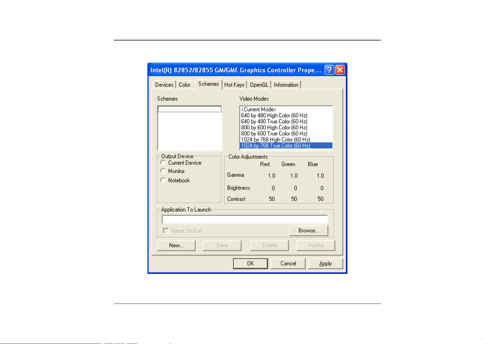
Schemes
78
Page 2
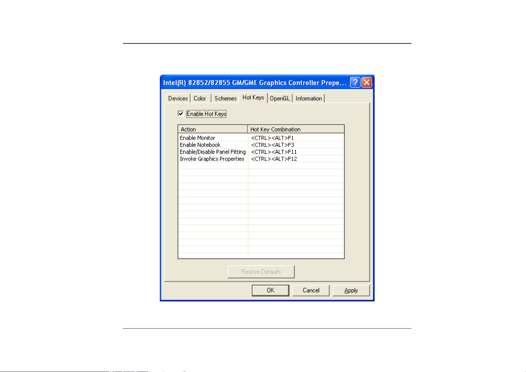
Hot Keys
79
Page 3
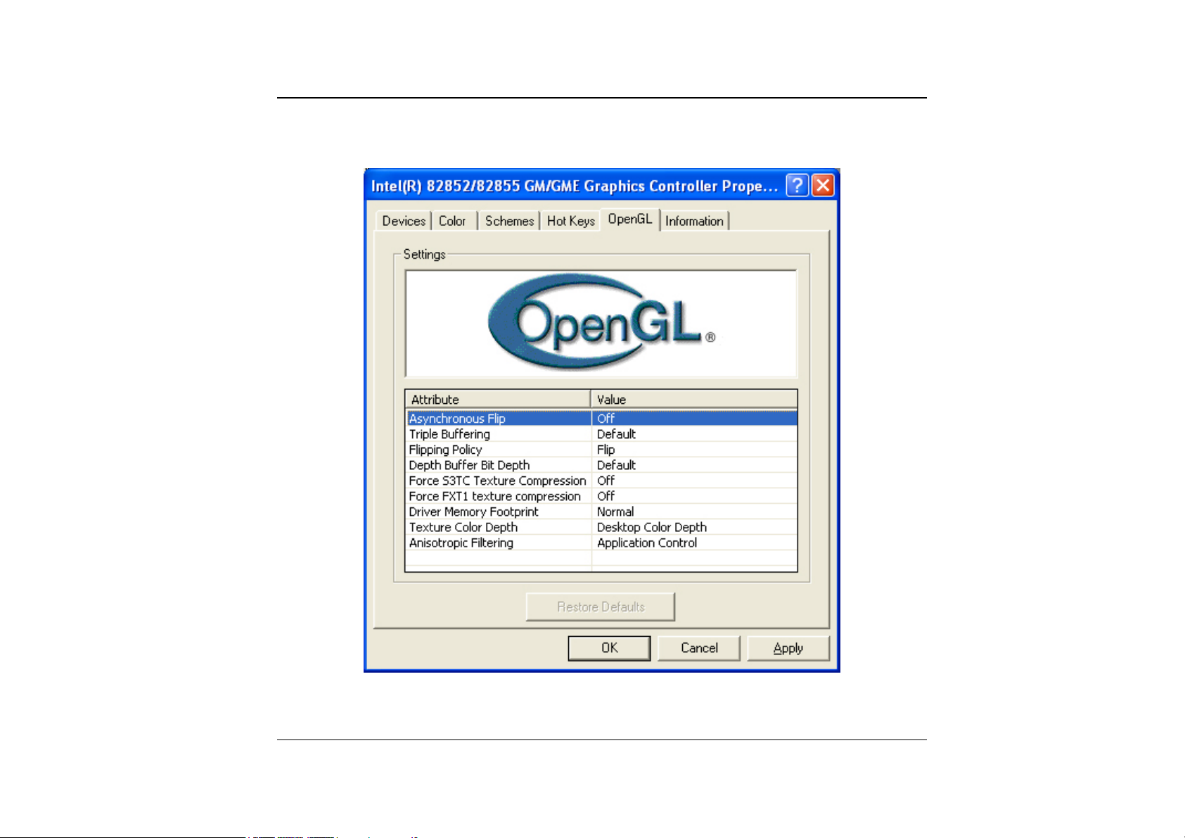
OpenGL
80
Page 4

Page intentionally left blank
81
Page 5

TTrroouubblleesshhoooottiinngg
This chapter describes locating and solving problems that you may encounter while
using your computer.
Locating a Problem
Problems with your computer can be caused by something as minor as an unplugged
power cord – or as major as a damaged hard disk. The information in this chapter is
designed to help you find and solve minor problems. If you try all the suggested
solutions and you still have a problem, make a list of what steps you have taken to
Page 6

correct the problem and contact your dealer.
Successful troubleshooting is the result of careful observation, deductive reasoning,
and an organized approach to solving the problem.
The problems that you will encounter can be divided into two basic categories:
hardware problems and software problems. Hardware problems can be further divided
into electrical and mechanical problems. You will know you have a hardware
problem if the screen is dark, the computer cannot read the disk drives, or you get an
error message during the Power-On Self Test (POST).
Software errors can occur at several levels. The ROM BIOS and the operating system
can give you a large number of error messages. On top of this, each application
software package has its own set of error messages. It is important to determine
whether the software error message you are getting is from the application or the
operating system. Once you know this, you can look in the respective manual for a
solution to the problem.
Checking Cables and Connections
Start by performing a careful visual inspection of the exterior of the computer. If no
LEDs are illuminated, make sure that your computer and its peripherals are getting
power and communicating with each other properly.
To check the power cables, and connections:
If you have been using battery power, connect the Notebook to an external
11..
power source and make sure that the battery has a charge.
If you are using the Notebook with the AC adapter, check the power outlet, the
22..
power cord, and any power switches that may affect your computer.
83
Page 7

Check the wall outlet or power strip with an item that you know is
functioning properly. A lamp or radio is a convenient item for checking the
power. You may also need to check the fuses and breakers in your electric
box.
If the outlet is controlled by a wall switch, make sure that the switch is on.
If the outlet is controlled by a dimmer switch, use a different outlet.
If your computer is plugged into a power strip with an On/Off switch, make
sure the switch is on.
With the computer’s power switched off, check all cable connections. If the
33..
computer is connected to any peripheral devices, look for loose or disconnected
cables.
If the computer is too close to a wall, a cable connection may be loose or the cables
may be crimped.
Do not substitute cables for different devices (other than the
manufacturer recommended cables) even if they look exactly alike. The
wiring inside the cable may be different.
When you are certain that you have power available and all connections are
44..
good, turn the computer on again. If the computer still does not start, you may
have a hardware problem.
The Power-On Self Test
The Power-On Self Test (POST) runs every time you turn on or reset the Notebook.
The POST checks memory, the main system board, the display, the keyboard, the disk
drives, and other installed options.
A few seconds after you turn on your computer, a copyright message appears on your
display screen. A memory test message appears next; as the test continues, memory
size increases until all installed memory is tested. Normally, the only test routine
visible on the screen will be the memory test.
84
Page 8

Two classifications of malfunctions can be detected during the POST:
Error messages that indicate a failure with either the hardware, the software, or
•
the Basic Input/Output System (BIOS). These critical malfunctions prevent the
computer from operating at all or could cause incorrect and apparent results. An
example of a critical error is microprocessor malfunction.
• Messages that furnish important information on the power-on and boot processes
(such as memory status). These non-critical malfunctions are those that cause
incorrect results that may not be readily apparent. An example of a non-critical
error would be a memory chip failure.
In general, if the POST detects a system board failure (a critical error), the computer
halts and generates a series of beeps. If failure is detected in an area other than the
system board (such as the display, keyboard, or an adapter card) an error message is
displayed on the screen and testing is stopped. It is important to remember that the
POST does not test all areas of the computer, only those that allow it to be
operational enough to run diagnostic programs.
If your system does not successfully complete the POST, but displays a blank screen,
emits a series of beeps, or displays an error code, consult your dealer.
General Hardware Problems
A few common hardware problems and suggested solutions are presented in the table
below:
Problem:
Solution:
follow the instruction on the installation of audio driver.
Problem:
Failure in the installation of the Audio driver.
Be sure to first remove the current audio device from your system. Please
The display screen is dark
85
Page 9

Solution:
Make sure that the computer is not in Suspend mode. Check the Brightness
controls for the screen. If the controls are turned too far down, the screen will be dark.
Problem:
Solution:
An incorrect date and time are displayed.
Correct the date and time using the DOS DATE and TIME commands or the
options in the Setup Utility. If the date and time become incorrect after a short time, your
CMOS battery may be depleted. Contact your dealer to change the battery.
Problem:
The message: “Invalid system disk, Replace the disk, and then press any key”
appears during boot.
Solution:
Check and make sure that you do not have a non-bootable floppy diskette
inserted in your floppy drive. If your USB FDD is empty, you may not have an operating
system installed on your drive. Contact technical support for assistance.
Problem:
You hear irregular beeps during operation of the Notebook and the system
halts.
Solution:
Problem:
The problem is beyond the scope of this manual. Contact technical support.
An unidentified message is displayed.
Solution:
Reboot the computer and run the BIOS system setup. Confirm the Setup
parameters. If the same message is displayed after booting up again, contact technical
support for assistance.
Problem:
Solution:
The system cannot access the CD-ROM/DVD-ROM drive.
Check that a CD is properly inserted in the drive. Make sure that you are using
the correct program for that kind of CD. For example, the system cannot read a data CD
using an audio program.
Problem:
86
You cannot operate the printer.
Page 10

Solution:
Check the printer cable connection. Ensure that the printer power switch is
turned on. Confirm that the printer is on-line.
Problem:
Solution:
You can’t save data to disk.
Ensure that the disk has been formatted.
Consult your operating system manual for information on formatting floppy diskettes.
Problem:
Solution:
Problem:
Solution:
The diskette is write-protected.
Eject the diskette, remove the write protection, and try again.
The diskette if full.
Try using another diskette or free up some space on the diskette. The disk
drive is not operating. Contact your dealer for support.
Problem:
You cannot use the mouse.
Check the cable connection. •
•
Check the mouse with another application to see if there is a software
incompatibility problem.
•
If possible, check the mouse with another computer to see if it works. If it
doesn’t operate on a different system, the mouse might be broken.
Contacting Your Dealer
If you still have a problem after reading the preceding sections, the next step is to
contact your dealer. Your dealer can determine if the problem is something that
requires the computer to be taken to the shop. Before you call your dealer, however,
prepare the following information:
87
Page 11

How is your computer configured? Your dealer needs to know what peripheral
•
devices you are using.
•
What messages, if any, are on the screen?
•
What software were you running at the time?
•
What have you done already to try to solve the problem? If you have overlooked
a step, your dealer may be able to solve the problem over the phone.
88
Page 12

Page intentionally left blank
89
Page 13

Uppggrraaddiinngg yyoouurr SSyyssttee
U
Upgrading your Memory
Refer to the following instructions and illustration for information on upgrading your
notebook's memory.
Turn off the computer and disconnect the AC adapter and all peripherals.
11..
Turn the notebook over so that the rear ports are facing you and locate the
22..
memory module compartment.
Remove the screws that secure the RAM module compartment cover and set it
33..
m
m
Page 14

aside in a safe place.
Remove the compartment cover and then angling it up and out.
44..
If you need to install a higher capacity module, gently push the edge clips on
55..
both sides to release the module. Angle the card slightly upward and gently
slide it from its edge connector slot. Store the card in the anti-static bag that
contains your new module(s).
To install the new memory card, hold the card with its gold edge connector
66..
toward the edge connector slot of the compartment. To help you orient the
cards, the edge connector has been made with two unequal-length sections.
You will only be able to insert the card in one direction.
Insert the edge connector into the slot. The gold edge connector of the card
77..
should not be visible when the card is fully inserted.
Press the card downward where you should hear an audible click as the latches
88..
of the connector secure the card in place.
Once the module is properly seated, you can replace the cover on this
99..
compartment.
Replace and tighten the screw.
1100..
91
Page 15

The Easy to Upgrade HDD Module
The hard drive in your notebook computer is made to be easily swapped out for
upgrading. You should back up your hard drive before attempting o change the hard
drive. Make sure that before you install a new drive, all the files in your system
should be backed up.
To upgrade your Hard Drive
92
Page 16

Power down the system completely. Turn the system over with the front of the
11..
unit facing you.
Remove the three screws that secure the compartment cover and set them in a
22..
safe place.
Slide the HDD cover away from the compartment.
33..
The drive is attached to a special bracket that secures it to the notebook
44..
computer. There are 4 screws hold the bracket. Remove the screws and set
them in a safe place.
Push the HDD slightly in the direction of the arrow as shown in the illustration
55..
to release it from the pins of the drive.
Gently hold the grip of the HDD, lift it up to release from its compartment.
66..
To install the new HDD, you will need to align the tabs on the drive bracket
77..
with the slots on the bay. Press down gently on the drive bracket until it
engages with the system. Do not force the drive into place this can bend the
pins on the hard drive.
Slide the compartment cover into place and be sure the screw holes on the cover
88..
align completely with the screw holes in the case.
Secure the cover with the three screws.
99..
Upgrading your System CPU
Refer to the following instructions and illustration for information on upgrading your
notebook's CPU
Turn off the computer and disconnect the AC adapter and all peripherals. From
11..
the rear side of your notebook, use your index finger to lift up the hinge cover
attached to the LCD screen.
Bend your LCD screen into 90 degree angle then carefully lift up the hinge
22..
cover.
93
Page 17

Remove the screen that is attached to the keyboard in order to remove the
33..
heatsink on top of the CPU.
94
Remove all the screws attached to the heatsink.
44..
Page 18

Before removing the screws, there are certain measures to followed in removing
55..
the heatsink
To remove the heatsink, first loosen the screw carefully.
66..
After loosening one screw, be certain that the next to be loosen should be the
77..
screw on its adjacent side as shown on the illustration.
Be sure to loosen all the screws first before removing it totally to
release the heatsink. Failure to do so will cause a major damage to
the heatsink.
Now you can totally remove all the screws also in that order when you first
88..
loosen the screw.
95
Page 19

Detailed Notebook Specifications
General
CCPPUU
•
Intel Pentium-M Banias processor from 1.3GHz to 1.7GHz, 1M L2 cache
•
Intel Dothan processor from 1.8GHz to 2.0GHz, 2M L2 cache
SSppeecciiffiiccaattiioonn
Page 20

478 pin uFC-PGA2 478 socket, CPU front-side bus up to 400MHz •
• TDP : 21W.
CCoorree LLooggiicc
•
Intel 855GM/GME,
•
Support FSB 400MHz
Memory
MMaaiinn MMeemmoorryy
•
2 expandable memory slot up to 2GB,1GB per DIMM Max. with 512Mb
technology
•
128/256/512 MB memory options
•
Two 200 pin SO DIMM type memory slots
•
2.5V TSOP/CSP/WBGA DDR SDRAM
•
Supports DDR266/333 Synchronous SDRAM
RROOMM
•
512KB Flash ROM factory option, 3V erase
•
Boot block protection
Mass Storage
HHDDDD
•
Support enhanced IDE (PIO mode 4) and bus master(Ultra DMA 33/66/100
mode).
•
Removable hard disk drive, 2.5” 9.5mm.
97
Page 21

MMoodduullee BBaayy
•
Supports CD-ROM/DVD-ROM/Combo Drive (DVD-ROM+CD-RW), DVD-RW,
DVD+RW, DVD-Dual; 5.25” 12.7mm height
•
Fast IDE and ATAPI interface CD-ROM/DVD-ROM/Combo Drive (DVDROM+CD-RW), DVD-RW, DVD+RW, DVD-Dual
PPooiinnttiinngg DDeevviicceess
•
Synaptics TouchPad
•
Support four way scrolling feature
KKeeyybbooaarrdd
•
US/Europe, DOS/V keyboard for Japan, full size keyboard alike pitch
•
300 mm keyboard with key stroke 3.0mm
•
Twelve function keys and Windows Function key
•
Internal keyboard works a standard 101/102 desktop keyboard
•
2 short-cut keys: WWW & eMail
Audio
CCoonnttrroolllleerr
• Built-in Intel ICH 4-M chipset
CCooddeecc
• Realtek ALC202A
98
Page 22

FFeeaattuurreess
•
•
•
•
•
Dual full-duplex Direct Sound Channels
Hardware SoundBlaster Pro for real-mode DOS legacy compatibility
18-bit ADC & DAC resolution
Support S/PDIF out
AC’97 2.2 & PC2001 compliant
I/O Ports
SSttaannddaarrdd PPoorrttss
•
One parallel port supported EPP/ECP (25-pin female D-connector)
•
One S-video TV out port for TV
•
One DC input port for External AC adapter (2-pin DC jack)
•
One Type II PCMCIA card socket
•
One video port for external analog VGA monitor (15-pin female D-connector)
•
USB 2.0 port x 2
•
MIC-in, headphone jack w/ adaptor for 5.1 channel SP/DIP support
•
RJ-11 jack for Fax/Modem
•
RJ-45 jack for LAN
•
IEEE 1394 mini-jack
PPCCMMCCIIAA
•
Controller : RICHO R5C551
•
Supports 1 PC Card/CardBus slot
•
Supports 16-bit & cardBUs PC Cards, PCI rev. 2.2 and PC Card Standard Release
7.0 compliant
99
Page 23

Integrated IEEE 1394a OHCI-link & two ports with IEEE 1394 internal PHY •
• Data transfer rate : 100/200/400 Mbps
Graphics and Video
CCoonnttrroolllleerr
• Intel 855GM/GME internal graphics.
FFeeaattuurreess
• High performance 3D graphics engine (floating triangle setup/rendering)
GGrraapphhiicc MMeemmoorryy
• Up to 64 MB of dynamic video memory allocation
LLCCDD DDiissppllaayy
• 14.1”XGA/15”XGA/15” SXGA TFT
Electrical
AACC AAddaapptteerr
• External universal type AC adapter, output maximum 65W
SSmmaarrtt BBaatttteerryy
100
•
Li-Ion battery @ 27 Whrs (4-cell); Optional 8-cell 53W
•
User interchangeable
•
Removable and rechargeable
•
3 hrs charge time while system off
Page 24

4 hrs charge time while system on •
•
Charging time for one battery pack : 3.5 hours to full charge when system off or
in suspend
•
More than 2.0 hrs w/ 4-cell battery, 4.0 hrs w/ 8-cell battery
Dimensions
•
326(W) x 258(D) x 25.3(H) mm/32mm (front/back)
Weight
•
2.4kg with 14.1” panel, Battery and DVD-ROM Drive installed
Operating Environment
TTeemmppeerraattuurree
•
Operating: 5°C ~ 35°C
•
Storage: -20°C ~ 60°C
HHuummiiddiittyy
•
Operating: 30% ~ 90% (non-condensing)
•
Non-operating: 10% ~ 90% (non-condensing)
AAllttiittuuddee
•
Operating: -200 to 10,000 feet above sea level
•
Non-operating: -200 to 30,000 feet above sea level.
Options
•
Spare Li-Ion Battery Pack : 4-cell battery and 8-cell battery
101
Page 25

•
Factory Option : 802.11b/g wireless LAN with MiniPCI slot
Memory Extension Card
•
Module bay : CD-ROM/ DVD-ROM/ Combo(DVD-ROM+CD-RW) Drive, DVD-
•
RW, DVD+RW, DVD-Dual
Bootable external USB FDD
•
Accessories
User‘s Manual & Driver CD title
•
•
AC Adapter
Power Cord
•
Software Specifications
SSyysstteemm SSooffttwwaarree
•
System BIOS: AMI BIOS
Supported Operating Systems
•
Standard Software Drivers
•
102
Optional Windows XP or above version
INTEL_INFINST driver,
VGA driver,
Audio driver,
Touch-Pad driver,
IR driver,
MDC Modem driver,
LAN driver,
MiniPCI Wireless LAN driver
 Loading...