

Elite Fitness IT 9310-E Owner's Manual
1
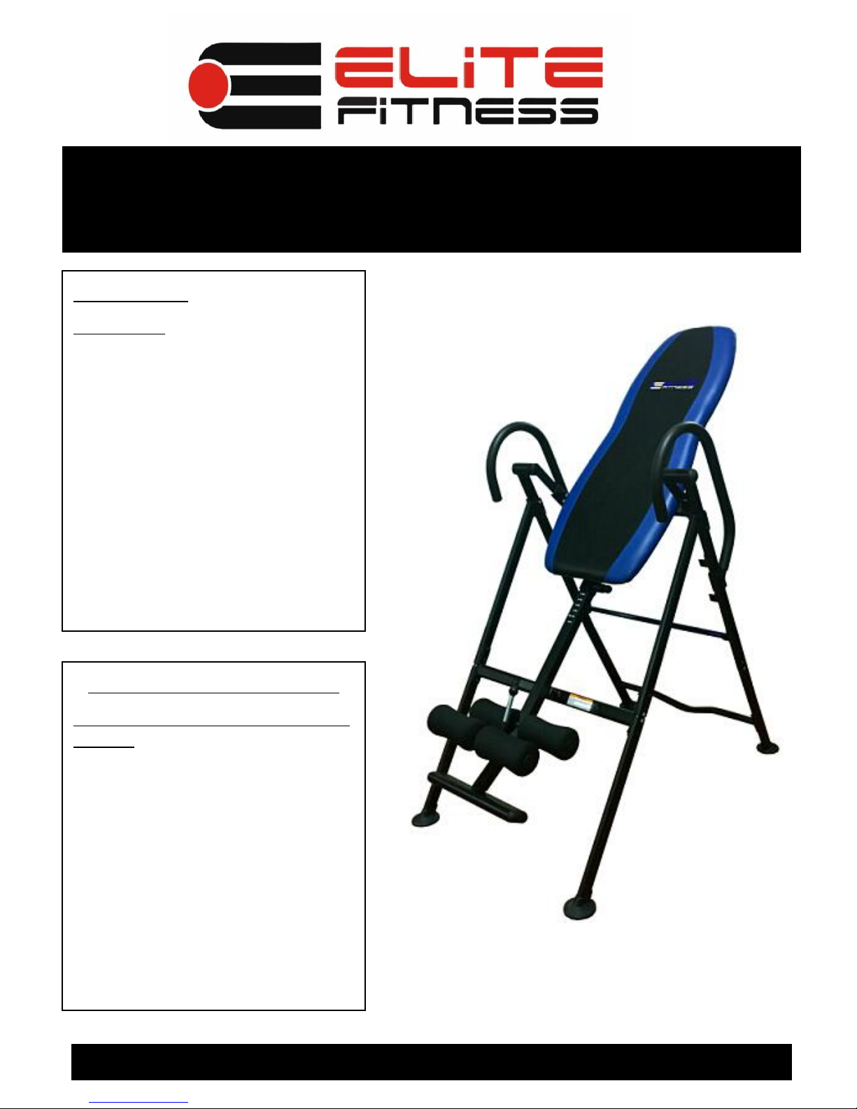
Deluxe Inversion Table
Model IT 9310-E
Owner’s Manual Version: 10114
Photo may differ from actual product
CAUTION:
WARNING: Do not use this
inversion table without a
physician’s approval.
Do not let children use the
inversion table unsupervised.
Read all instructions carefully
before using.
Tighten all bolts before using
equipment.
Leave adequate space to
properly invert.
.
Questions/ Comments
PLEASE DO NOT CONTACT THE
STORE
Elite Fitness is committed to
providing the very best of quality
and customer satisfaction for all of
the products we distribute. If for
any reason , you are dissatisfied
with the product you have
purchased or need assistance in
any way, please do not hesitate to
contact our knowledgeable support
staff at: 623-888-6379
Mon.-Fri 8:00 am – 6:00 pm Pacific Time

2
BEFORE BEGINNING ASSEMBLY…
Take a few moments to familiarize yourself with the specific parts and hardware included with your
product. Make sure all the parts and hardware are included in the carton and examine them for any
damage that may have occurred in transport. Some parts may be pre-assembled and pre-installed.
CAUTION
WARNING:
BEFORE STARTING ANY INVERSION PROGRAM, CONSULT YOUR PHYSICIAN.
Read all instructions very carefully before using equipment
Tighten all bolts securely before using equipment
Product Warranty
Limited Liability
Extreme Products Group warrants that this product will be free from defects in materials and workmanship
for a period of 1 year on the frame, and 90 days on all other parts from date of purchase. This warranty
applies only to the original purchaser when purchase of the product is from an authorized retailer and is for
personal or household use, but not when the sale is for commercial use. This warranty is not transferable.
EXCEPT FOR THE LIMITED EXPRESS WARRANTY STATED HEREIN, EXTREME PRODUCTS
GROUP DISCLAIMS ALL OTHER EXPRESS OR IMPLIED WARRANTIES, INCLUDING BUT NOT
LIMITED TO IMPLIED WARRANTIES OF MERCHANTABILITY AND FITNESS FOR A PARTICULAR
PURPOSE. SOME STATES DO NOT ALLOW LIMITATIONS ON HOW LONG AN IMPLIED WARRANTY
LASTS, SO THE ABOVE LIMITATIONS MAY NOT APPLY TO YOU.
Extreme Products Group, will not be liable for any loss or damage, including incidental or consequential
damages of any kind, whether based upon warranty, contract or negligence and arising in connection with
the sale, use or repair of the product.
SOME STATES DO NOT ALLOW THE EXCLUSION OR LIMITATION OF INCIDENTAL OR
CONSEQUENTIAL DAMAGES, SO THE ABOVE LIMITATION OR EXCLUSION MAY NOT APPLY TO
YOU. THIS WARRANTY GIVES YOU SPECIFIC LEGAL RIGHTS AND YOU MAY HAVE OTHER
RIGHTS THAT VARY FROM STATE TO STATE.
In the event of failure of this product to conform to this warranty during the warranty period, please call
Extreme Products Group Customer Service Number at 623-888-6379 for assistance in the repair or
replacement of the product or any covered part. Extreme Products Group will repair or replace, at its own
option, the product or any covered part, except that this warranty does not cover damage caused by
accident ( including transit) , or repairs or attempted repairs by any person not authorized by Extreme
Products Group, or by vandalism, misuse, abuse, or alteration. The Warranty Period is based on the
purchase date of the product validated by the Authorized Retailers Register Receipt, or valid copy of
transaction statement. Shipping and Handling is not included. By continuing with the assembly and use of
this products acknowledges your understanding of the Warnings and Warranty Guidelines stated above.
If you require technical support under this warranty, please call Customer Service at ( 623-888-6379).
* For Any Parts Required, DO NOT CALL TECHNICAL SUPPORT. Please visit our web site at :
www.extremeproductsgroup.com
3
Parts Listing
Part# Description Qty Check Part# Description Qty Check
1L Top Base frame-LEFT 1 24 Leg Tube Adjustment Knob 1
1R Top Base frame-RIGHT 1 25 Foam Leg Rollers 4
2 Bottom Base frame-FRONT 2 26 Round End Caps 4
3 Bottom Base frame-REAR 2 27 Hexagonal Bolt-M8*15mm 3
4 Support tube-FRONT 1 28 Hexagonal Bolt-M8*50mm 1
5 Support tube-REAR 1 29 Metal Bushing for Rear Leg Tube 1
6 Handlebar 2 30 Safe-T Bar 1
7 Backrest Support frame 1 31 Oval End Caps-Foot Rest 2
8 Backrest Pad 1 32L Top Base frame-REAR 1
9 Bolt M8 M8*30 mm 4 32R Top Base frame-REAR 1
10 Body Height Adjustment Tube 1 33 Connecting Bracket 2
11 Adjustable Leg Hold Tube 1 34 Hexagonal Bolt-M8*20 2
12 Leg Tube-REAR 1 35 Bolt-M6*40 1
13 Foot Rest Plate 1 36 WasherΦ12*Φ6.2*1.2 1
14 Base Frame End Caps 4 37 Nut M6 1
15 Bolt M8 M8*35mm 10 38 Spring 1
16 Flat Washer ∮8.2*∮16*1.5mm 32 39 Round Spring Insert 1
17 Lock Nut M8 25 40 Plastic Spacer 4
18 Hexagonal Bolt-M8*30mm 4 41 Plastic Round End-Cap 2
19 Hexagonal Bolt-M8*35mm 6
42 Square End Cap-for Part10 1
20 Hexagonal Bolt-M8*20mm 4
43 Square End Cap 4
21 Ball Pin ∮8*53mm 1
44 Round End Cap-for handlebars 2
22 Ball Pin ∮8*65mm 1
45 Plastic WasherΦ20*Φ9.5*2.0 4
23 Height Adjustment Knob 1

4
Exploded View
* For Any Parts Required, DO NOT CALL TECHNICAL SUPPORT. Please visit our web site: www.extremeproductsgroup.com
* For Any Parts Required, DO NOT CALL TECHNICAL SUPPORT. Please visit our web site: www.extremeproductsgroup.com
5
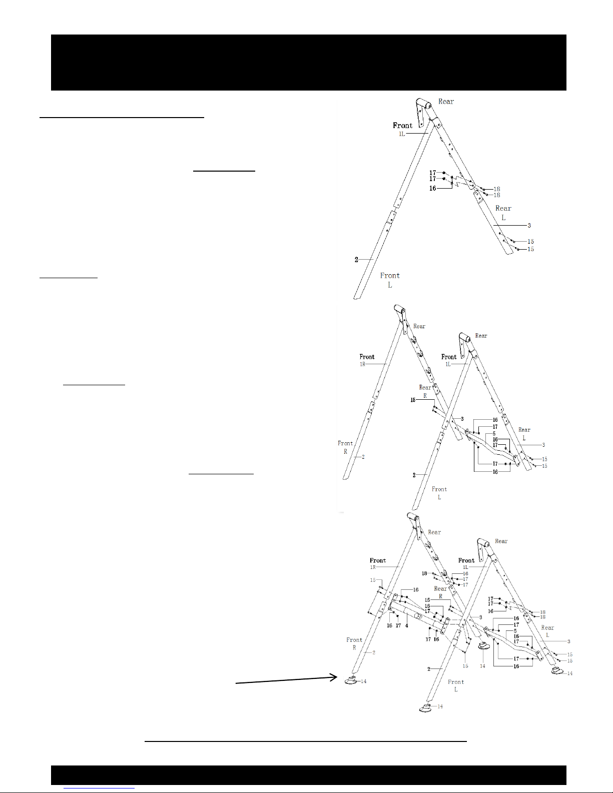
Base Frame and Handlebar Assembly
STEP 1- Base Frame
Unpack Base frame from Carton.
Attach (1L) Upper Left A- Frame
into (2L) Front Left Base Frame
and (3L) Right Rear Base Frame.
Repeat for Right Side of Frame.
Connect the Rear Section of the
A-Frame using 2 Bolts (18) 2
Washers (16), and 2 Nuts (17) on
the left and right side.
Attach the Rear Lower Cross Bar
(5) into the assembled sections of
the A- Frame using 2 bolts (15)
2 Washers (16) and # nuts ( 17)
on each side as shown.
Attach the Front Center Cross Bar
(4) to each of the Side A-Frames
using 3 Bolts (15) 3 Washers (16)
and 3 Nuts (17) on each side.
Attached Floor Caps (14) to the
completed frame as shown.
* For Any Parts Required, DO NOT CALL TECHNICAL SUPPORT. Please visit our web site: www.extremeproductsgroup.com
16
TIGHTEN ALL BOLTS AT THIS TIME
 Loading...