

Elite Acoustics Engineering
StompMIX 4
4 Channels Digital Mixer Pedal
Quick Guide Handbook - V1.00
48V
OUT2
OUT1
A
page
parameter
system
CH2
CH1
B
StompMix 4
WHAT IS IN THE BOX
Your StompMix 4 package contains the following:
(1) StompMix 4 unit
(1) AC to 12VDC Power Supply Adapter
NOTE: Due to continuous development and improvements of our products, features and specications are subject to
change without notice. All weights and measures are approximate.
For a copy of the complete User’s Manual, please visit: www.eliteacoustics.com
OUT2
CH2
OUT1
A
page
parameter
system
CH1
B
StompMix 4
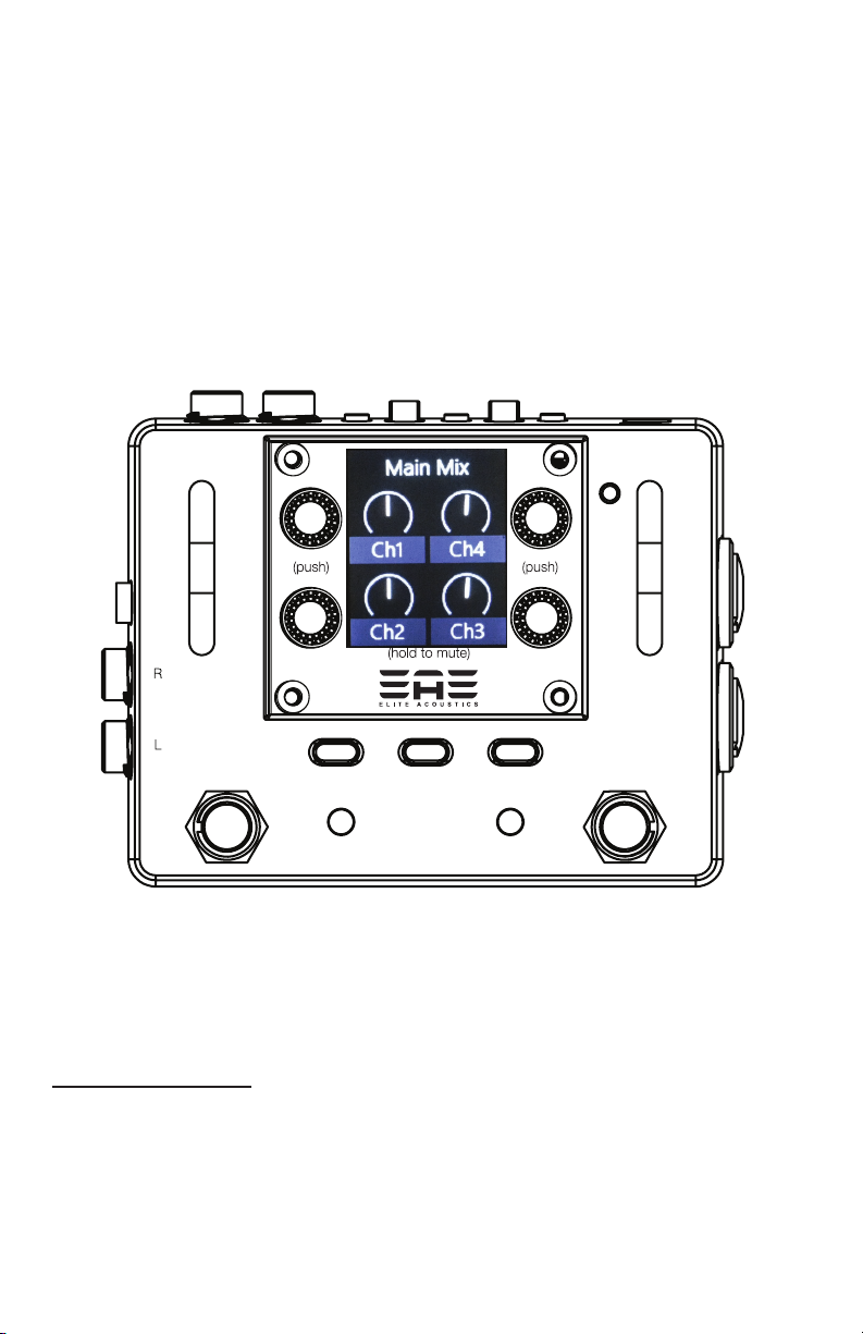
LCD FUNCTIONS
Menu Buttons with LCD:
Press any of the 3 menu buttons(black button located to the
below theLCD) or 4 encoders(blue knobs located around LCD)
to access and adjust features and settings. Most menus have
several pages of options, which are adjusted by turning the
corresponding encoder.
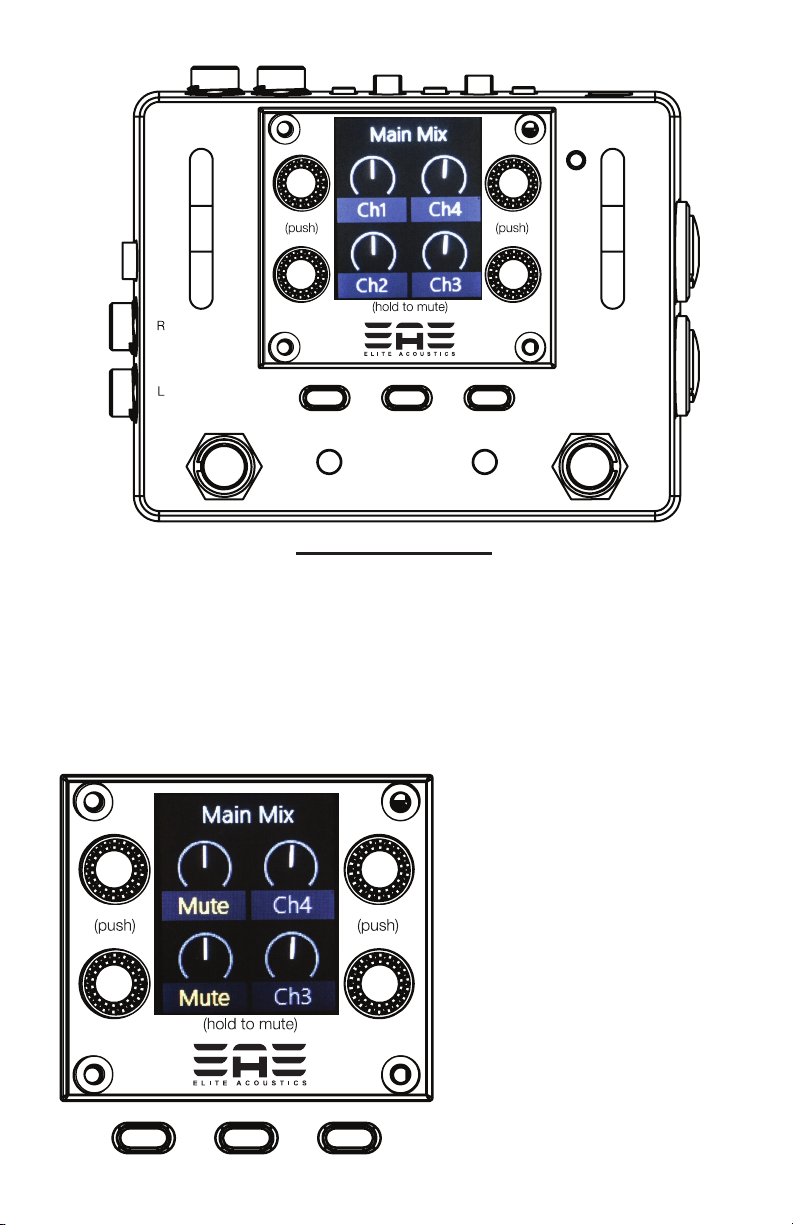
“MUTE”
HOLD down the
Corresponding encoder
to MUTE or UNMUTE each
channel.
page
parameter
system
page
parameter
system
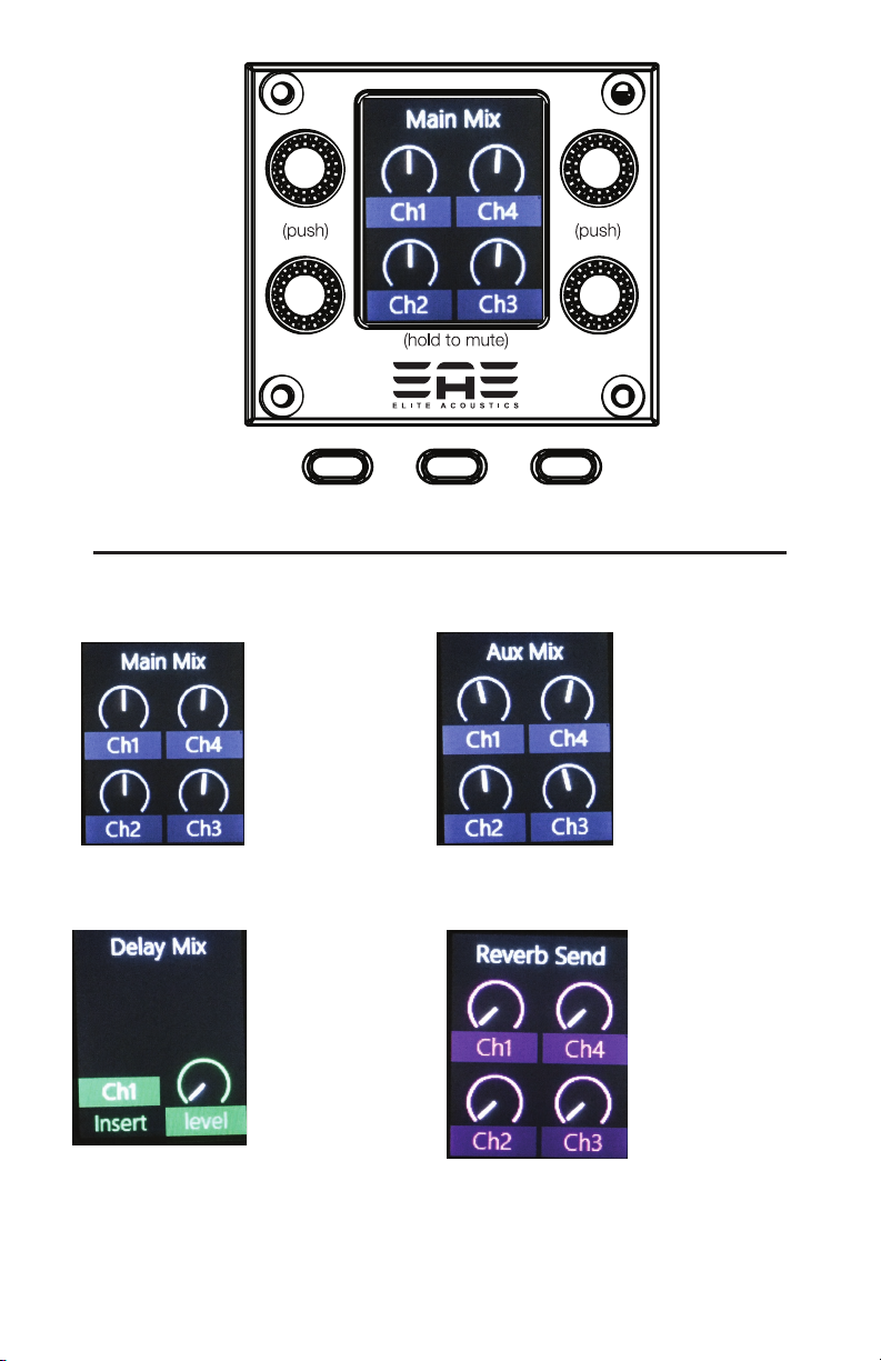
PRESS the “page” button to access these FUNCTIONS
“Main Mix”
Adjust the level
of each of the 4
channels sent
to the Main MIX
Outputs.
“Delay Mix”
Select the
Chan which
delay is
inserted and
Delay Mix
Level.
“Aux Mix”
Adjust the level
of each of the 4
channels sent
to the Aux Mix
Outputs.
“Reverb Send”
Adjust the Reverb
Send level of
each of the 4
channels.
page
parameter
system
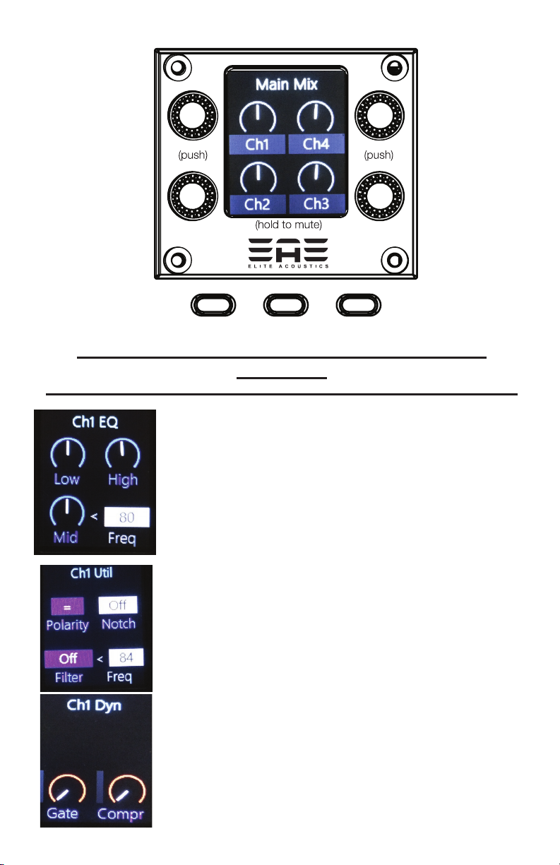
PRESS the corresponding Encoder knob for these
Functions.
use the corresponding Encoder knob for these Functions.
“Channel EQ”
Adjust for
each channel
Low
Mid
Mid Freq
High
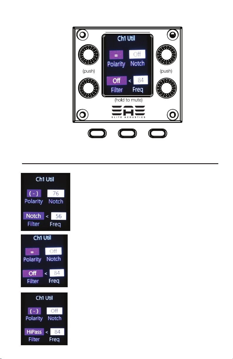
“Channel Util” - more details on next page.
Polarity (=) or (-)
Notch Filter
Filter - Off/Highpass/Notch
Filter Freq.
“Channel Dyn”
Adjust levels for
Gate
Compressor
page
parameter
system
use the corresponding Encoder knob for these Functions.
“Channel Util”
Input Phase Polarity is (-) Reversed.
Notch - 76 Hz.
Filter - Notch 56 Hz.
“Channel Util”
Input Phase Polarity is (=) - NOT reversed.
Notch - OFF
Filter - OFF
Filter Freq. - 84 Hz.
“Channel Util”
Input Phase Polarity is (-) Reversed.
Notch - OFF
Filter - HiPass
Filter Freq. - 84 Hz.

Editing “Main Mix” parameters
page
parameter
system
PRESS the “parameter” button to access these FUNCTIONS
Preset “Parameter” key
Adjust the Main Mix stereo panning
for each of the 4 channels.
Preset “Parameter” key
Adjust the Main Mix output Level.

Editing “Aux Mix” parameters
page
parameter
system
PRESS the “parameter” button to access these FUNCTIONS
Preset “Parameter” key
Adjust the AUX stereo panning for
each of the 4 channels.
Preset “Parameter” key
Adjust Aux Send connection - “Pre”
or “Post”
Pre - Pre “Main Mix level”
Post - Post “Main Mix level”
““
Adjust the Aux Mix output Level.

Editing “Delay Mix” parameters
page
parameter
system
PRESS the “parameter” button to access these FUNCTIONS
page
Preset “Parameter” key
Adjust the 4 Delay Parameter by the
corresponding encoder knobs.
parameter
system

Editing “Reverb Send” parameters
page
parameter
system
PRESS the “parameter” button to access these FUNCTIONS
page
Preset “Parameter” key
Adjust the 3 Reverb Parameter by the
corresponding encoder knobs.
parameter
system

page
parameter
system
PRESS the “system” button to access
these FUNCTIONS
Input Meters
It is critical to adjust the normal input levels to be
below -12db level to avoid Clipping the inputs of
the StompMix 4. Distortion can occur when inputs
are clipping. CHAN 1 and CHAN 2 have input level
knobs and PAD switches, CHAN 3 and CHAN 4
require input level control from the extenal device.
“Memories”
There are 10 scenes that can be save.
Use the Corresponding encoder to make changes.
“Push” - push the encoder
“Hold” - push/hold the Encoder.
(*) next to the “Mem” number means sences is stored in
that location.
“Assigns”
“A” and “B” footswitch have assignable functions. See
next page for more details.
Main Mix and Aux Mix outputs can be assigned to the
1/4” L/R jacks or the 1/8” jack.

page
parameter
system
USE the corresponding Encoder knob for these Functions.
“Assigns”
“Assigns”
“A” - Memory
DOWN
“B” - Memory
UP
“Assigns”
“A” - CHAN 1/2
ON/OFF
“B” - CHAN 3/4
ON/OFF
“Assigns”
“AUX” Mix
output to 1/4”
L/R
“MAIN” Mix
output to 1/8”
“A” -- CHAN 1
ON/OFF
“B” -- CHAN 2
ON/OFF
“Assigns”
“A” -- Reverb
ON/OFF
“B” -- Delay TAP
“Assigns”
“MAIN” Mix output
to 1/4” L/R
“AUX” Mix output
to 1/8”

Rear Panel.
1) USB mini jack (for Updating unit.)
2) DC input Jack (+12VDC Center Positive.)
Unit will operate from +9VDC to +12VDC “Must be Center Positive”
3) +48V phomton power switch - Both CHAN 1 and CHAN 2.
4) CHAN 1 LEVEL and PAD
5) CHAN 2 LEVEL and PAD
6) CHAN 3 input
OUTPUTS
OUTPUT 2
1/8” Jack.
OUTPUT 1
L/R 1/4”
Jacks.
OUT2
OUT1
CHAN 1/2
CH2
Combo Jack
input.
CH1
MIC or 1/4”
A
page
StompMix 4
parameter
system
B
Line Inputs.

SYSTEM SPECIFICATIONS
• System Architecture : Ultra high-speed high-capacity DSP with lossless A/D and D/A
conversion. Integrated Digital Mixer supports routing and seamless signal-level management
for four fully congurable audio channels. Color Graphic LCD presents a highly intuitive GUI for
settings and save & recall.
• Digital Effects and Controls: Channel Parametric EQ, Notch Filter, Selectable HiPass/Notech
Filter, Compressor, Noise Gate, Main and Aux panning, Reverb,Delay, Real-Time Chan-Level Bar
Graphs, Save & Recall Programs.
. Footswitch Controls “A” and “B” - Assigable functions include Memory Up/Down, Mutes,
Reverb bypass and Tap Delay.
• Nominal output levels (1 kHz): -10 dBu
• MIC Inputs: XLR balanced
. TS Inputs: 1/4” input jacks
• Phantom Power: +48V
•
• Displays: Color Graphic LCD; phantom power
• Connectors: CH1 & 2: Input jacks (Combo Jack - mic XLR 1/4” Line), CH3/4: (1/4” Line),
Output 2 - 1/8” TRS jack
Output 1 - 1/4” L/R outputs,
Power supply - DC in jack
• Power Supply: DC 12V 500mA or Higher
• Current Draw: 400 mA
• Accessories: AC cord, AC adaptor, Owner’s manual
• Dimensions: 4.5”W x 3.6”D x 2.3”H
• Weight: 1.8 lbs
For most updated details, please visit: www.eliteacoustics.com or contract us via email.
Product specif ications subject to change without notice.

Legal Notice: CALIFORNIA PROPOSITION 65 WARNING
WARNING: Cancer and Reproductive Harm - www.P65Warnings.ca.gov.
THIS DEVICE COMPLIES WITH PART 15 OF THE FCC RULES. OPERATION IS SUBJECT TO
THE FOLLOWING TWO CONDITIONS.
1. THIS DEVICE MAY NOT CAUSE HARMFUL INTERFERENCE, AND
2. THIS DEVICE MUST ACCEPT ANY INTERFERENCE RECEIVED, INCLUDING
INTERFERENCE THAT MAY CAUSE UNDESIRED OPERATION.
WARRANTY (USA ONLY)
Contact the Distributor in your area for service and warranty info.
Elite Acoustics Engineering Inc. warrants this product to be free of defects in material and workmanship (excluding
battery) for a period of 1 year from the date of original retail purchase. Elite Acoustics Engineering Inc. warrants
the Speaker’s Battery for 90 days from the date of original retail purchase. This warranty is enforceable only by the
original retail purchaser. To be protected by this warranty, the purchaser must complete and return the enclosed
warranty card within 14 days of purchase. During the warranty period EAE shall, as its sole and absolute option,
either repair or replace, free of charge, any product that proves to be defective on inspection by EAE or its authorized
service representative. To obtain warranty service, contact Elite Acoustics Engineering Technical Support via email:
RMA@eliteacoustics.com. PRE-AUTHORIZATION MUST BE OBTAINED BEFORE SENDING ANY PRODUCT
TO AN ELITE ACOUSTIC ENGINEERING SERVICE CENTER. All inquires must be accompanied by a description
of the problem. All authorized returns must be sent to the EAE repair facility postage prepaid, insured and properly
packaged. EAE reserves the right to update any unit returned for repair. EAE reserves the right to change or
improve the design of the product at any time without prior notice. This warranty does not cover claims for damage
due to abuse, neglect, alteration, or attempted repair by unauthorized personnel and is limited to failures arising
during normal use that are due to defects in material or workmanship in the product. Any implied warranties,
including implied warranties of merchantability and tness for a particular purpose, are limited in duration to the
length of this limited warranty. Some states do not allow limitations on how long an implied warranty lasts, therefore
above limitation may not apply to you. In no event will EAE be liable for incidental, consequential, or other damages
resulting from the breach of any express or implied warranty, including among other things, damage to property,
damage based on inconvenience or on loss of use of the product, and, to the extent permitted by law, damages
for personal injury. Some states do not allow the exclusion of limitation of incidental or consequential damages,
so the above limitation or exclusion may not apply to you. This warranty gives you specic legal rights, and you
may also have other rights, which vary from state to state. This warranty only applies to products sold and used in
the United States of America. For warranty information in all other countries please refer to your local distributor.
©Elite Acoustics Engineering Inc.
 Loading...