

Elite access systems Sl-3000 series Installation Instructions Manual
™
SL-3000
HIGH TRAFFIC COMMERCIAL SLIDE GATE OPERATORS
SERIES
INSTALLATION INSTRUCTIONS & MANUAL BOOK FOR
ARCHITECTS, GENERAL CONTRACTORS & DEALERS
www.eliteaccess.com
© COPYRIGHT 1988 BY ELITE ACCESS SYSTEMS, INC.
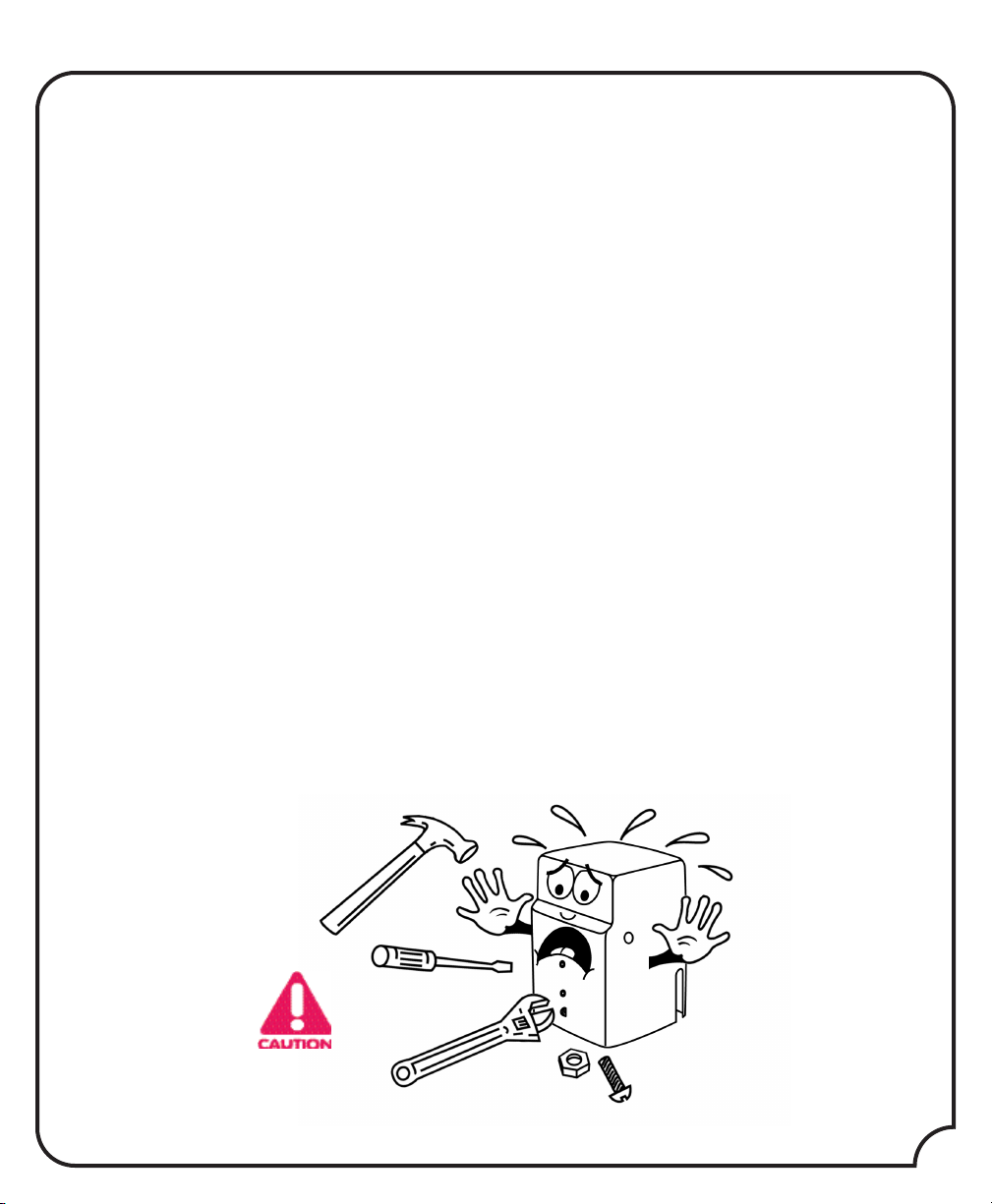
TABLE OF CONTENTS
GATE POST WARNING . . . . . . . . . . . . . . . . . . . . . . . . . . . . . . . . . . . . . . . . . . . . . . . . . .2
WARNING SIGNS . . . . . . . . . . . . . . . . . . . . . . . . . . . . . . . . . . . . . . . . . . . . . . . . . . . . .3
TYPES OF INSTALLATIONS . . . . . . . . . . . . . . . . . . . . . . . . . . . . . . . . . . . . . . . . . . . . . . . .4
HOW TO CONNECT THE CHAIN FOR DIFFERENT TYPES OF INSTALLATIONS . . . . . . . . . .5
CEMENT WORK . . . . . . . . . . . . . . . . . . . . . . . . . . . . . . . . . . . . . . . . . . . . . . . . . . . . . . .6
DISTANCE BETWEEN THE OPERATOR AND GATE . . . . . . . . . . . . . . . . . . . . . . . . . . . . . . .7
CHOOSING MOVEMENT DIRECTION . . . . . . . . . . . . . . . . . . . . . . . . . . . . . . . . . . . . . . .7
HOW TO CONNECT POWER (120V) . . . . . . . . . . . . . . . . . . . . . . . . . . . . . . . . . . . . . . .8
ADJUSTING GATE TRAVELING DISTANCE . . . . . . . . . . . . . . . . . . . . . . . . . . . . . . . . . . . . .8
TWO-WAY ADJUSTABLE REVERSING SENSOR . . . . . . . . . . . . . . . . . . . . . . . . . . . . . . . . . .9
ADJUSTABLE TIMER & ADDITIONAL LIMIT SWITCH . . . . . . . . . . . . . . . . . . . . . . . . . . . . . .9
MASTER & SLAVE WITH TIMER . . . . . . . . . . . . . . . . . . . . . . . . . . . . . . . . . . . . . . . . . . . .10
MASTER & SLAVE / NO TIMER . . . . . . . . . . . . . . . . . . . . . . . . . . . . . . . . . . . . . . . . . . .11
THREE PUSH-BUTTON SYSTEM . . . . . . . . . . . . . . . . . . . . . . . . . . . . . . . . . . . . . . . . . . . .12
TERMINAL INPUT CONNECTIONS . . . . . . . . . . . . . . . . . . . . . . . . . . . . . . . . . . . . . . . . .13
SAFETY AND EXIT LOOP . . . . . . . . . . . . . . . . . . . . . . . . . . . . . . . . . . . . . . . . . . . . . . . .14
EMERGENCY RELEASE . . . . . . . . . . . . . . . . . . . . . . . . . . . . . . . . . . . . . . . . . . . . . . . . .15
HOW TO REPLACE THE CONTROL BOARD . . . . . . . . . . . . . . . . . . . . . . . . . . . . . . . . . .16
YOU WILL HEAR A “BEEP” SOUND WHEN . . . . . . . . . . . . . . . . . . . . . . . . . . . . . . . . . .16
TROUBLESHOOTING / LED INFORMATION CENTER . . . . . . . . . . . . . . . . . . . . . . . . . . . .17
SL-3000 PARTS . . . . . . . . . . . . . . . . . . . . . . . . . . . . . . . . . . . . . . . . . . . . . . . . . . . . . . .18
LIST OF SL-3000 PARTS AND MAINTENANCE . . . . . . . . . . . . . . . . . . .INSIDE BACK COVER
© 1988 BY ELITE ACCESS SYSTEMS, INC.
ALL RIGHTS RESERVED. NO PART OF THIS MANUAL MAY BE REPRODUCED IN ANY MEANS:
GRAPHIC, ELECTRONIC OR MECHANICAL, INCLUDING PHOTOCOPYING WITHOUT THE
EXPRESSED WRITTEN PERMISSION OF THE PUBLISHER. MATERIALS, COMPONENTS AND
SPECIFICATIONS ARE SUBJECT TO CHANGE WITHOUT NOTICE.
RELEASE 4
PLEASE DO NOT TOUCH ME!...
...UNLESS YOU ARE AN AUTHORIZED SERVICE TECHNICIAN! THANK YOU.
1
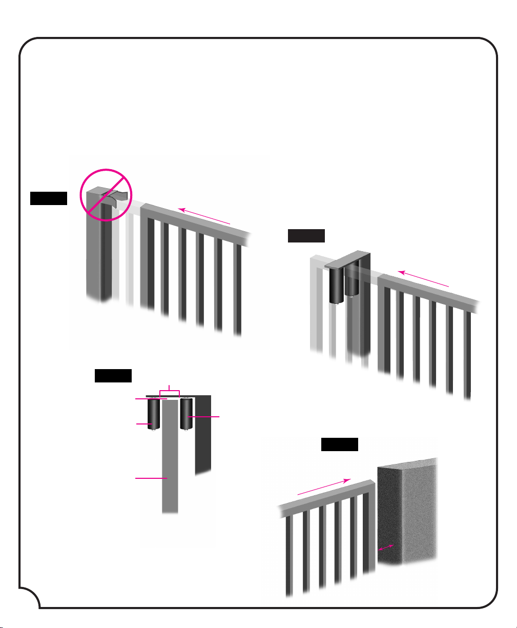
Fig.B1
Closing
CORRECT
.25"
3"
Fig.B2
2"x 2"
gate frame
catch roller
catch roller
Opening
5"
Fig. C
wall
Fig. A
Closing
WRONG
GATE POST WARNING
IMPORTANT NOTICE!
Because the coasting distance may vary due to changes in temperature, Elite does NOT recommend
the installation of a stop or catch post in front of the gate's path as shown in Fig. A. To do so will
cause the gate to hit the post in certain instances. Elite only recommends installation of catch rollers
on the side of a catch post with a minimal distance of three inches between the rollers as shown in
Fig. B1 & B2. Also when fully open the end of the sliding gate must stop at least five inches from any
wall or other object as shown in Fig. C.
2
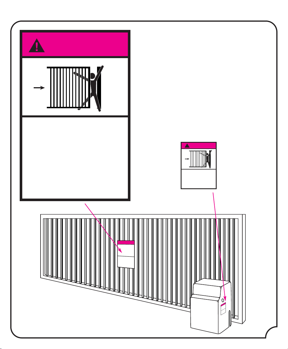
WARNING
Moving Gate Can Cause
Serious Injury or Death
KEEP CLEAR! Gate May Move at Any Time
Do Not Allow Children to Operate Gate or
Play in Gate Area
Operate Gate Only When Gate Area is in
Sight and Free of People and Obstructions
WARNING SIGNS
Moving Gate Can Cause
Serious Injury or Death
WARNING
!
Operate Gate Only When Gate Area is in Sight,
Free of People, and Clear of Obstructions
Do Not Allow Children to Operate Gate or Play in Gate Area
This Entrance is for Vehicles Only. Pedestrians
Must Use Separate Entrance
Read Owner’s Manual and Safety Instructions
Free of People, and Clear of Obstructions
This Entrance is for Vehicles Only. Pedestrians
IMPORTANT!
Installers are required to adhere to this procedure:
The UL required Warning Signs must be installed in
plain view and on
gate installed. Each sign is made with fastening holes
in each corner and should be permanently secured in
a suitable manner. Also the warning sticker should
be placed on the operator so it is clearly visible.
both sides of each commercial
3
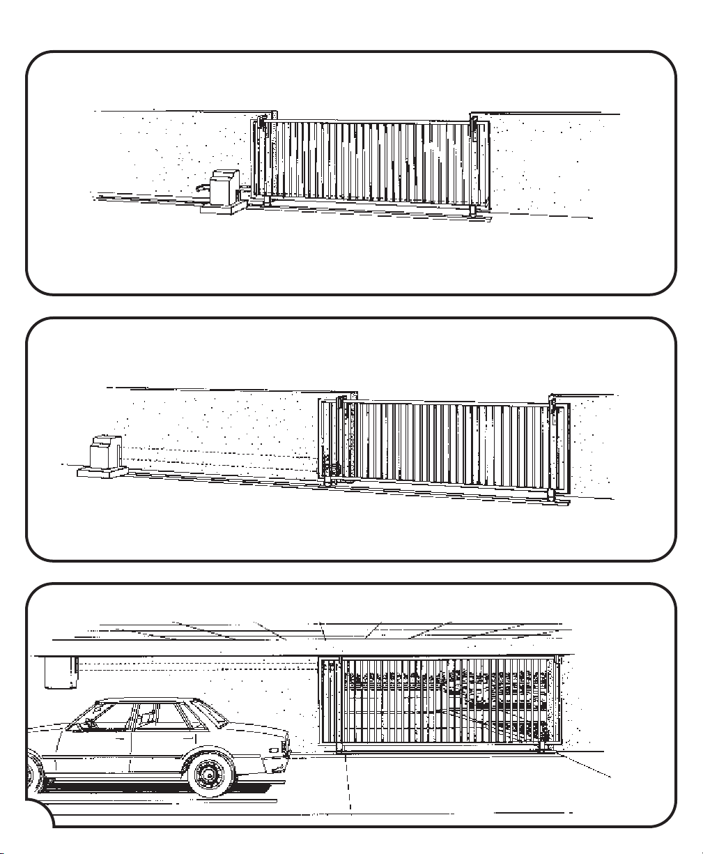
TYPES OF INSTALLATIONS
FRONT INSTALLATIONS
Reason: Cost efficient.
REAR INSTALLATIONS
4
Reason: Chain is not visible.
CEILING MOUNT UNDERGROUND PARKING
Reason: Space efficient - chain is not visible.
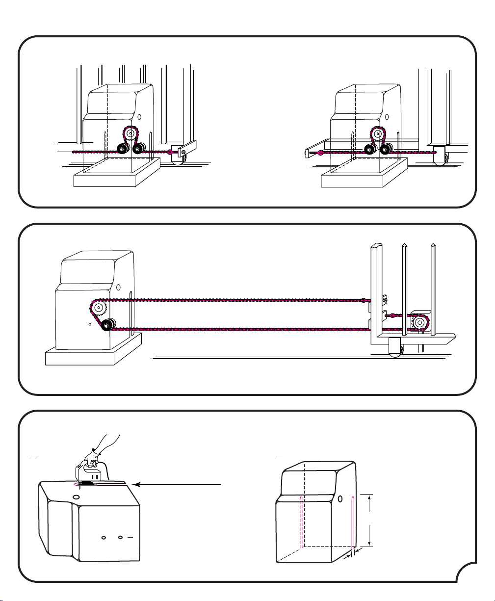
HOW TO CONNECT THE CHAIN
FRONT INSTALLATIONS
Weld front bracket with gate in open position. Weld rear bracket with gate in closed position.
REAR INSTALLATIONS
1
Cut the cover by 17
⁄2” Make sure the sprocket box is sealed.
REAR INSTALLATIONS: HOUSING MODIFICATION
A B
The housing must be
modified for a rear
installation.
Cut the chain access
slots to the exact
specifications shown in
picture “B”at the right.
2"
Important: For safe
operation of the gate
opener do not cut the
slots any wider or
longer than shown.
Do not modify the
housing in any way
171⁄2"
other than specified.
5
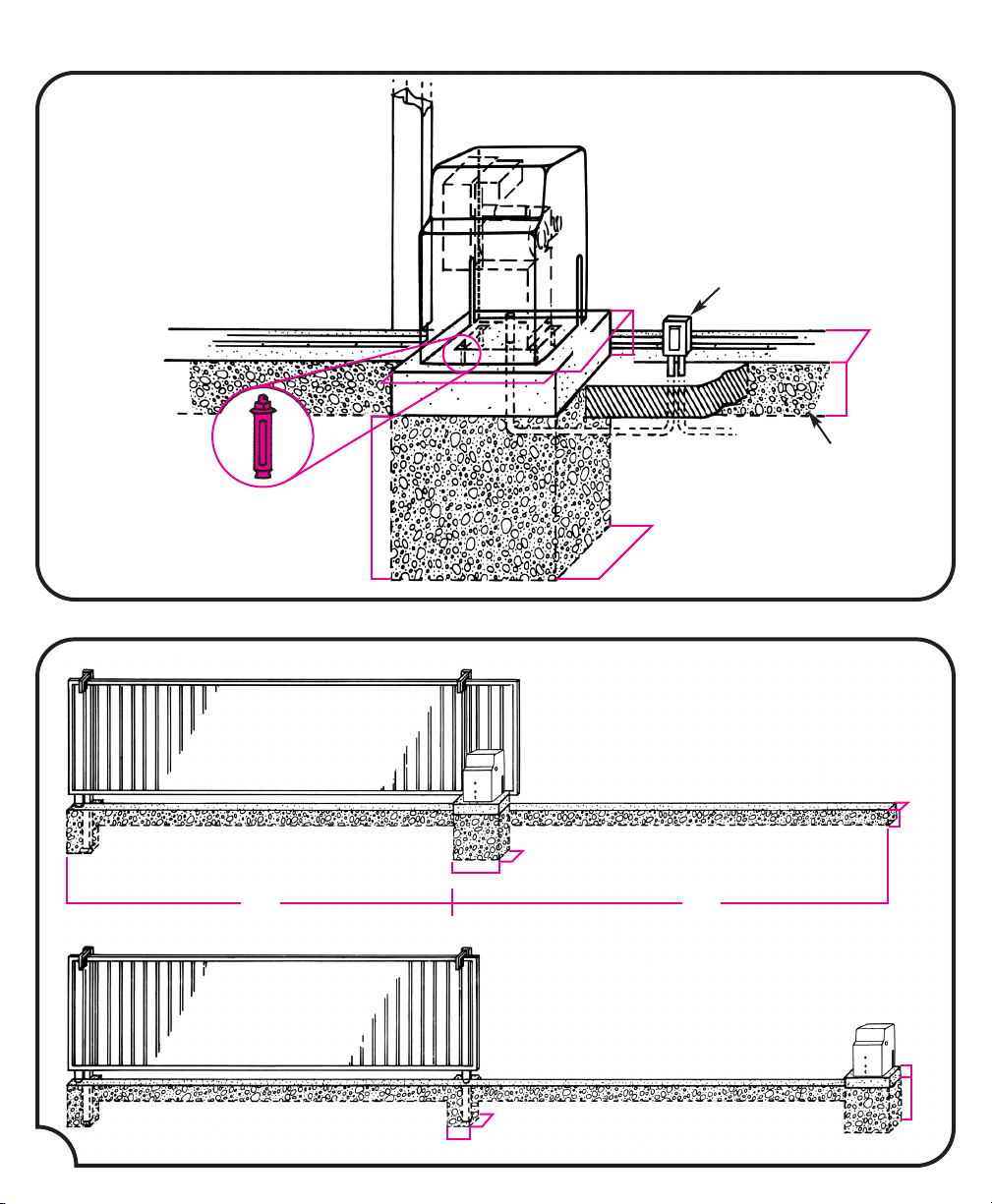
CEMENT WORK FOR THE PAD AND GATE
Suggested installation for dirt ground.
The measurements depend on the type
of ground (ie., asphalt, cement, dirt)
24"
6"
BELL BOX
3
⁄4" PVC
10"
1
⁄2" x 31⁄2"
RED HEAD BOLT
20’
24"
24"
24"
8"
CONCRETE
BED
24"
10"
8"
24"
22’
6
6"
24"
12"
12"
 Loading...