

Page 1
Rev.042417 DR
1
www.eliteproav.com
Electric Wall/Ceiling Projection Screen
Saker Plus
Series
User’s Guide
Important Safety & Warning Precautions
Make sure to read this user’s guide and follow the procedures below.
Caution: The screen’s Black Top Drop is already set to its maximum drop distance. There is NO extra
Black Top Drop in the roller. Please be aware of this as it will void your warranty with Elite ProAV.
Unapproved changes or modifications (except for cutting the power cord for hardwire installations) to this
unit are prohibited and will void your warranty.
•
Please retain this user’s guide for future reference.
•
To avoid damaging the unit, do not use with any unauthorized accessories not recommended by the
manufacturer.
•
Handle the unit carefully during transportation to avoid any damages.
•
To ensure safe and reliable operation, direct connection to a properly grounded power source is
advised.
•
The power outlet supplying power to the unit should be close to the unit and easily accessible.
•
Do not install the unit on uneven or inclined surfaces.
•
Do not put heavy objects on the power cord and position it properly to avoid creating a trip
obstacle.
•
Never overload the power cord to prevent an electric shock or fire due to a loose contact or a short
circuit.
•
There are not user servicea ble parts in this unit. Do not attempt to disassemble this unit by yourself.
No one except authorized technicians can open and make repairs to this unit.
•
Make sure the power source this unit is connected to has a continuous power flow.
•
If there is need to use an extension cord, make sure the cord has an equal rating as the appliance to
avoid overheat.
•
Do not handle the power plug when your hands are wet or your feet are in contact with water.
Do not use this unit under the following circumstances.
•
Disconnect the power cord under the conditions of heavy rain, wind, thunder or lightning.
•
Avoid direct Sunshine, rain shower and moisture.
•
Keep away from fire sources and high temperature to prevent this device from overheating.
•
Cut off the power supply first before transportation or maintenance.
•
Fully disconnect from the power supply when the unit is not in use for a long period of time, as
should be done with any other electric household appliance.
•
To avoid possible injury and/or an electric shock, do not attempt to use the screen if there is
obvious damage or if there are any evident broken parts.
Page 2
Rev.042417 DR
2
www.eliteproav.com
WARNING
The Screen’s Top Black Drop is already set to its maximum drop distance. There is NO extra top black
drop in the roller. Please be aware of this as it will void the limitation of your warranty.
Individual modifications to this product are prohibited and will void the warranty with the manufacturer.
Please contact Elite ProAV Customer Service for any questions.
NOTE:
This equipment has been tested and found to comply with the limits for a Class B digital device, pursuant to
Part 15 of the FCC Rules.
These limits are designed to provide reasonable protection against harmful interfe rence in a residential
installation. This equipment generates and can radiate radio frequency energy and, if not installed and used
in accordance with the instructions, may cause harmful interference to radio communications.
However, there is no guarantee that the interference will not occur on a particular installation. If this
equipment causes harmful interference to radio or television reception, which can be determined by turning
the equipment off and on, the user is encouraged to try to correct the interference by one or more of the
following measures.
✓ Reorient or relocate the receiving antenna of the device which may be causing the
interference.
✓ Increase the separation between the screen and the device’s receiver.
✓ Connect the equipment into a different power outlet other than the device.
Pre-Installation
1. Carefully unpack the screen.
2. Always handle the screen in a leveled position on a clean surface.
3. In order to protect the screen from exposure to stains, keep the screen out of contact with foreign
particles such as dust, sawdust, and/or liquids.
NOTE
Regardless of the mounting method, the screen should be securely supported so that the vibration or
pulling on the viewing surface will not cause the casing to become loose or fall. The installer must insure
that the fasteners used are of adequate strength and suitable for the installation location.
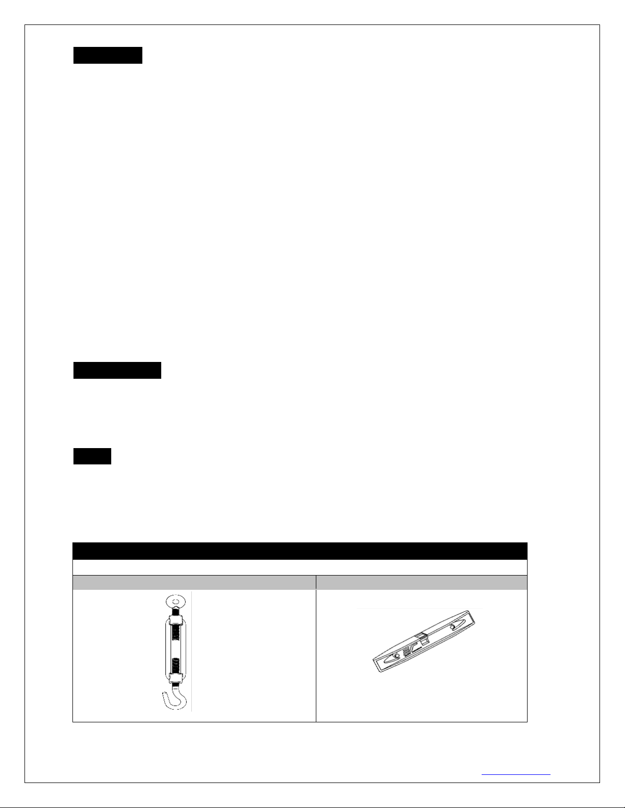
Hardware Parts List
Please make sure all parts listed below are included before proceeding with the installation.
A.M10*Suspended Hook x 4 pcs
B. 20cm*Bubble leveler x1pc
Page 3
Rev.042417 DR
3
www.eliteproav.com
Installation Instructions
Recessed Installation
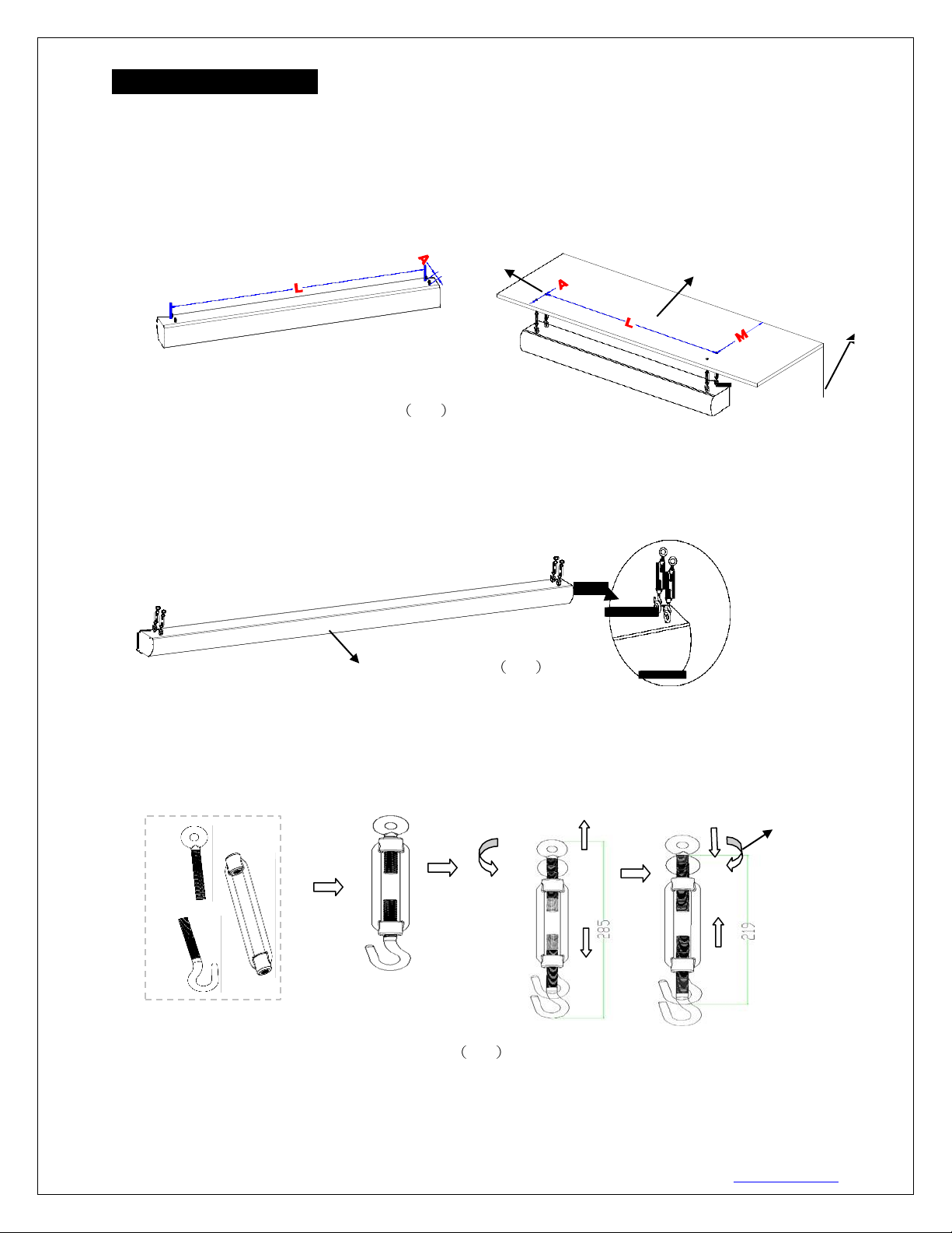
1. Select the installation location for your screen. Measure the distances between each eye bolt (Shown as
measurements L and A in Fig.1). Mark the installation area on the ceiling based on the measurements
taken. Using the marks as a guideline, drill a hole in the ceiling for each suspension bolt. The distance
between the installation hole (M) and the wall should be no longer than the measurement A. Insert one
eye bolt of the M10 Suspended hooks into the predrilled holes.
Hole
Ceiling
Wall
Fig.1
2. Connect the center component of the M10 Suspended hooks to the eye bolts installed above the ceiling.
Once properly secure, connect the third component of the M10 Suspended hooks. Attach the suspended
hooks(4xM10) individually to each of the 4 eye bolts located on the top of the screen (A/B/C/D) .
D.
A
C.
B
The Screen
Fig.2
3. After the installation is complete, if the screen is not leveled, you can adjust the height of the suspended
hooks to level the screen. Below are the adjustment methods for the suspended hooks.The maximum
and minimum adjustable lengths are shown in Fig 3.
3
1
Clockwise
rotation
Counter-
clockwise
rotation
2
Suspended hook
① ② ③ ④
Fig.3
Page 4
Rev.042417 DR
4
www.eliteproav.com
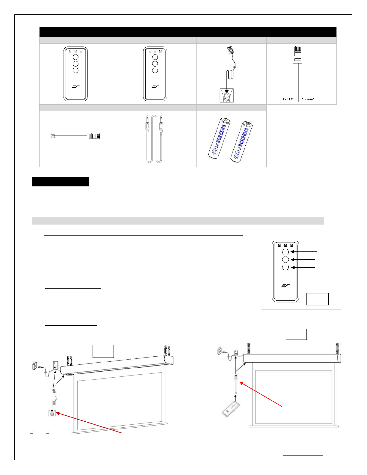
Saker Plus Series | Controls and Accessories
A. IR Remote
B. RF Remote
C. Wall switch control box
D. 5-12 volt trigger cable
E. IR extended “eye” receiver
F. Wireless 5-12v trigger cable
G. AAA batteries
Screen operation
Electric Current: Depending upon region, your EliteProAV™ screen will operate on 110v, or 220v voltage.
1. After ensuring the power outlet & screen are compatible (voltage), plug the power cord into the power outlet.
2. Once the screen’s has power, you’ll be able to control it using any of the 6 methods described below.
6 ways to control your Saker Plus
1. IR remote control (Item A, Fig 1) and IR “Eye” Receiver (Item E, Fig 2):
The Infrared functions by direct line of sight contact with a beam range of 30
feet. The IR “Eye” receiver plugs directly into the screen’s RJ-45 input to
present a low profile line-of-sight control option for your IR remote control
even in a recessed ceiling installation. Once connected, simply aim the IR
remote at the IR “Eye” receiver to control the screen.
2. RF Remote Control (Item B): The radio waves eliminate the need for a
direct line of sight with a range of 100 feet.
UP
STOP
DOWN
IR/RF remote
Fig.1
3. 3-Way Wall Switch (Item C, Fig 3): The 3-way wall switch
is a wall mount control box with an up/stop/down button and
plugs directly into the scree n’s RJ-45 input.
Fig.2
Fig.3
IR “eye” receiver
3 Way Wall Switch
(does not have IR sensor)
Page 5
Rev.042417 DR
5
www.eliteproav.com
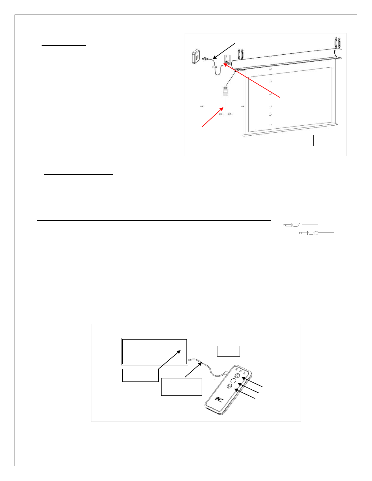
4. 5-12 volt trigger (Item D, Fig 4): The built-in 5-
12V trigger input allows your screen to synchronize
its drop & rise with the projector’s power cycle.
The screen deploys when the projector powers on
and will retract when the projector powers off. The
5-12 volt RJ45 cable connects to your projector’s
trigger output via a separate cable that may or may
not be provided by the manufacturer of the
projector. The trigger feature will not work without
an output cable from the projector, but it can be
tested by connecting the Red (+) and Green (-)
cable to a 9-volt battery.
5-12 volt trigger cable
3 prong power cord
RJ45 Input
Fig.4
5. Wireless 5-12 volt trigger (Item F, Fig 5): The RF remote control serves as a dual purpose, independently as a
handheld remote control, or in conjunction with the Wireless 5-12 volt trigger cable. The radio frequency
technology can be programmed to send a wireless signal to synchronize its drop & rise with the projector’s power
cycle.
Here’s how to set up your Wireless 5-12 volt trigger | Synchronization Instructions
Step1: Connect one end of the 3.5mm wireless 5-12 volt trigger cable to the RF remote
Step 2: Connect the other 3.5mm end of the wireless 5-12 volt trigger cable to your projector
Step 3: Make sure to unplug your screen from the power outlet
Step 4: Hold the UP button on your RF remote
Step 5: While holding the UP button, plug the screen back to the power outlet
Step 6: Wait 5 seconds and then release the UP button
Step 7: Your 5-12V wireless trigger should now be activated with your screen and ready to be used and able to
control your screen with your projector’s power cycle
Repeat the steps again if not successful.
(Please be aware, the projector on/off cycle may take longer to fully activate. It usually takes around 20-30
seconds for full off and on cycle each time)
The back of the
projector
Fig 5
DC 5-12V out
Wireless 5-12V
trigger cable
U P
S t op
D own
Page 6
Rev.042417 DR
6
www.eliteproav.com
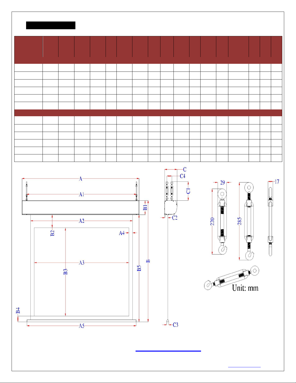
Dimensions Table
Model
Numbers
A
A1
A2
A3
A4
A5
B
B1
B2
B3
B4
B5
C
C1
C2
C3
C4
Unit:
Inches
SK200XVW2
176.0
169.2
163.9
160.0
2.0
167.9
135.0
6.7
6.0
120.0
2.4
128.3
6.7
8.7-11.2
1.9
1.0
2.6
SK235XVW2
204.0
197.2
191.9
188.0
2.0
195.9
158.0
6.7
8.0
141.0
2.4
151.3
6.7
8.7-11.2
1.7
1.0
2.6
SK265XVW2
228.0
221.2
215.9
212.0
2.0
219.9
178.1
6.7
10.0
159.0
2.4
171.4
6.7
8.7-11.2
1.1
1.0
2.6
SK200XHW2
190.3
183.5
178.3
174.3
2.0
182.2
113.1
6.7
6.0
98.1
2.4
106.4
6.7
8.7-11.2
1.9
1.0
2.6
SK235XHW2
220.8
214.0
208.8
204.8
2.0
212.7
132.3
6.7
8.0
115.2
2.4
125.6
6.7
8.7-11.2
1.7
1.0
2.6
SK265XHW2
247.0
240.2
234.9
231.0
2.0
238.9
149.0
6.7
10.0
129.9
2.4
142.3
6.7
8.7-11.2
1.1
1.0
2.6
Unit: mm
SK200XVW2
4471
4298
4164
4064
50
4264
3430
170
152
3048
60
3260
170
221-284
48
25
67
SK235XVW2
5182
5009
4875
4775
50
4975
4014
170
203
3581
60
3844
170
221-284
42
25
67
SK265XVW2
5791
5618
5484
5385
51
5585
4524
170
254
4039
61
4354
170
221-284
28
25
66
SK200XHW2
4834
4661
4528
4428
50
4628
2873
170
152
2491
60
2703
170
221-284
48
25
67
SK235XHW2
5609
5436
5303
5203
50
5403
3360
170
203
2927
60
3190
170
221-284
42
25
67
SK265XHW2
6274
6101
5966
5867
51
6068
3785
170
254
3299
61
3614
170
221-284
28
25
66
Note: Data Error: ±1"
For more information, technical support or your local EliteProAV
contact,
please visit
www.eliteproav.com
 Loading...