

Page 1
Aeon AcousticPro UHD Series
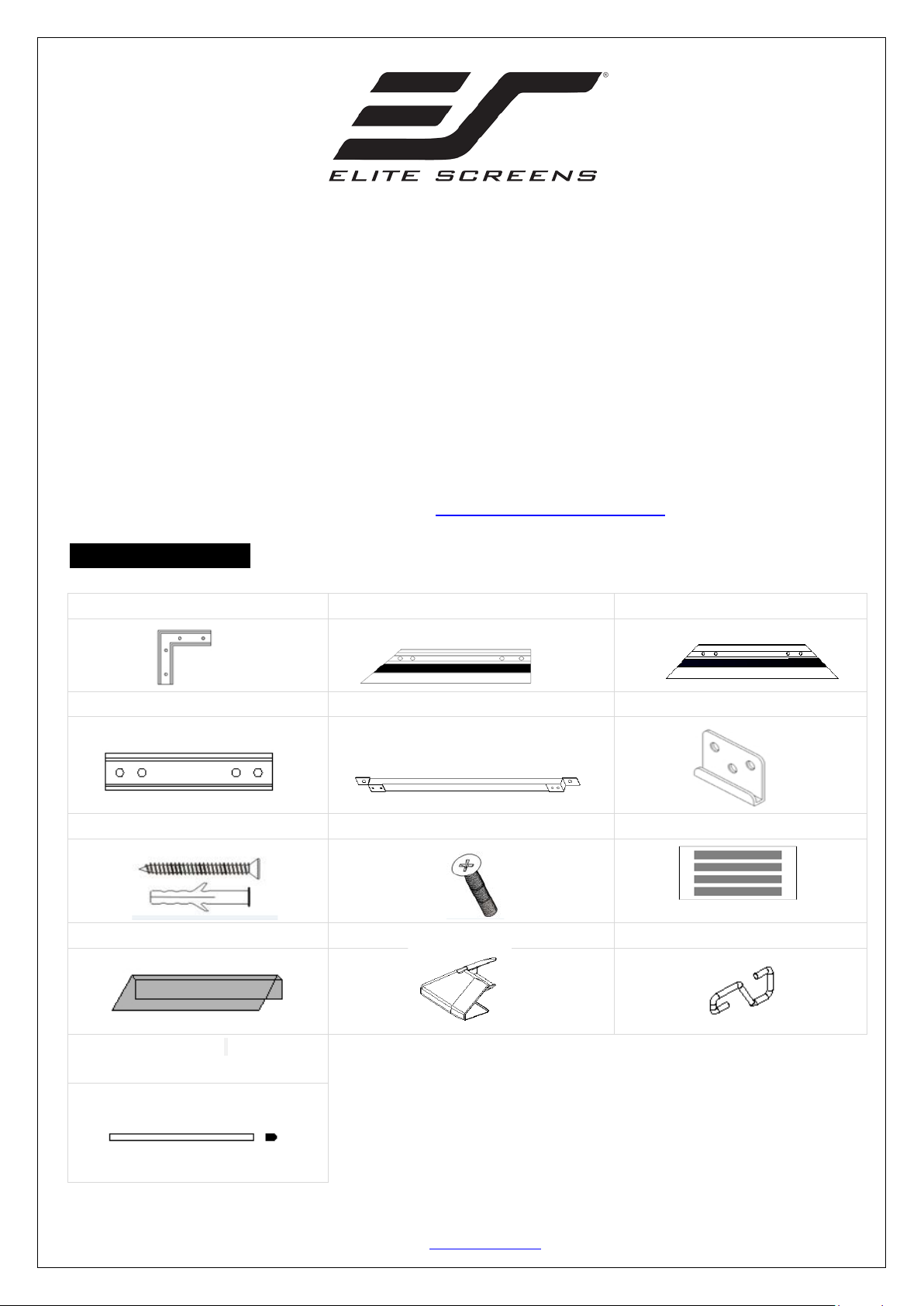
A. Elbow joint x 4 pcs
B. Top/Bottom horizontal fame x 4 pcs
C. Left/Right vertical frame x 2 pcs
D. Center joints x 2 pcs
E. Center Support bar x 1-2 pcs
F. Wall brackets x2-3 pcs
G. M5x50 screws and anchor x 6 pcs
H. M5x15 screw x 24 pcs
I. Black Tape x 1 bag
J
K. Plastic corner sleeve x 4 pcs
L. Hook
EDGE FREE® Fixed Frame Sound Transpare nt Projection Screen
User’s Guide
Product Description: The Aeon AcousticPro UHD Series is a fixed frame projection sc reen tha t u ses Eli te ’s EDGE
FREE® technology. The EDGE FREE
Edge trim a s an installation option to further enhance the frame appearance and absorb projector overshoot.
optional
For more information on the LED kit please visit:
Hardware and Parts List
Please make sure all parts listed below are included before installation.
LED backlighting kit is available for added visual appearance.
® design resembles a giant size flat panel TV display. The Aeon includes
An
http://www.elitescreens.com/led
. Edge trim x6 pcs
M. Fiberglass rod x 6 pcs &
Plastic sleeve x 12 pcs
Rev.041717-DR www.elitescreens.com 1
Page 2
Horizontal long frame (B)
Elbow Joint (A)
push
push
Elbow Joint (A)
Vertical short frame (C)
Top left Frame
Frame Assembly
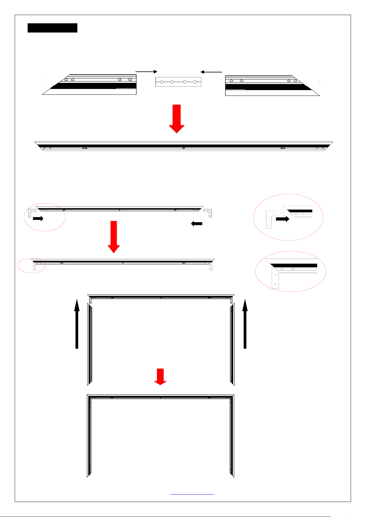
1. Insert the cente r jo in t in to o ne of the ½ horizontal frames (B) and fasten it with the two M5x15 screws (H).
2. Insert the other ½ horizontal frame piece to the center joint and fasten also using two M5x15 screws.
3. Repeat steps 1 and 2 for assembling the second hor izontal fram e.
Push Push
Top right Frame
Center Joints
Horizontal frame
4. Insert the elbow joint (A) into each end of the horizontal frames (B) as shown below.
5. Insert the two vertical short frames (C) into the elbow joint (A).
Vertical short frame (C)
Horizontal long frame (B)
Rev.041717-DR www.elitescreens.com 2
Page 3
Horizontal Long frame (B)
push
push
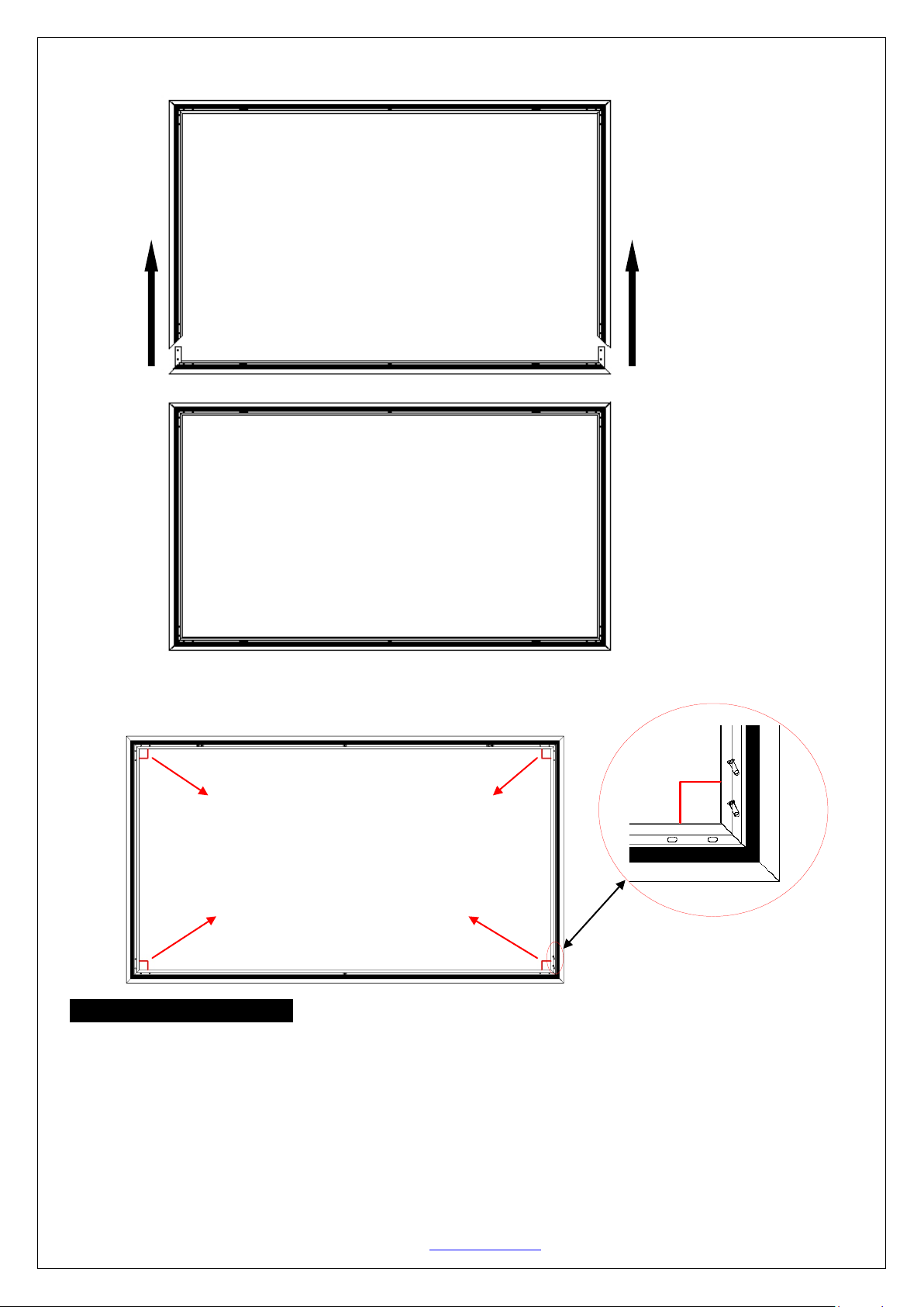
6. Join the remaining horizontal long frame (B) with the frame built in the previous steps as shown below.
7. Make sure all four corners are properly in place to form a perfect square. Then fasten the four angles with
the M5x15 Screws (H).
Four corners join correctly to form a perfect
square. Use the included screwdriver to
fasten the M5x15 screws (H) into each
corner by aligning the frame screw holes to
the holes in the elbow joint (A).
Screen Material Installation
1. Lay the screen material completely flat with the front facing down on a clean surface in a horizont al positi on.
The back side of the sc re en m ateria l should be placed upwards.
Note: The back side of the material has the velcro borders all around the edges.
2. Ca refull y and gently place the assembled frame on top of the screen material as shown below. Make sure to not
allow the angle edge of the frame to come in direct contact with the screen material to avoid puncturing it.
Rev.041717-DR www.elitescreens.com 3
Page 4
Screen material back facing up
3) Fold over second side
4) Repeat until all four
Velcro
D
A
D
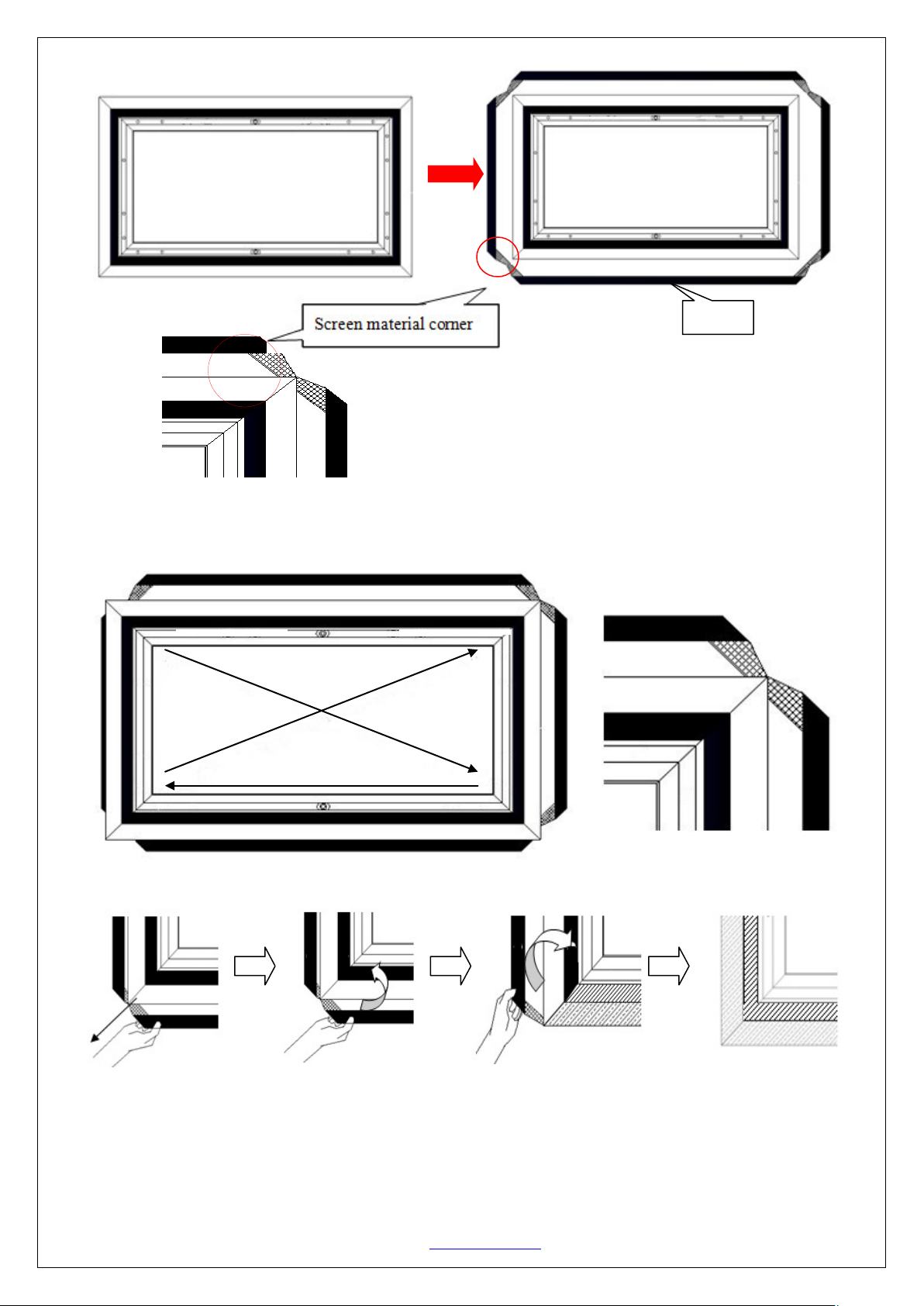
3. After all of the corners of the frame have been properly aligned, attach the material to the frame in the following
order A→B→C→D (see instructions below for details).
C
Attach the screen materia l to the corne rs as shown b elo w.
B
1) Stretch the screen
material in the direction
of the arrowhead.
4. After all four corners have been attached; please check whether the frame corners are wrapped by the screen
material. If not, please loosen the velcro connection and repeat the above steps so the frame is not exposed.
Rev.041717-DR www.elitescreens.com 4
2) Fold over and attach
material to the velcro
strip of the frame.
and attach to frame
sides are done in the
order A, B, C, D
Page 5
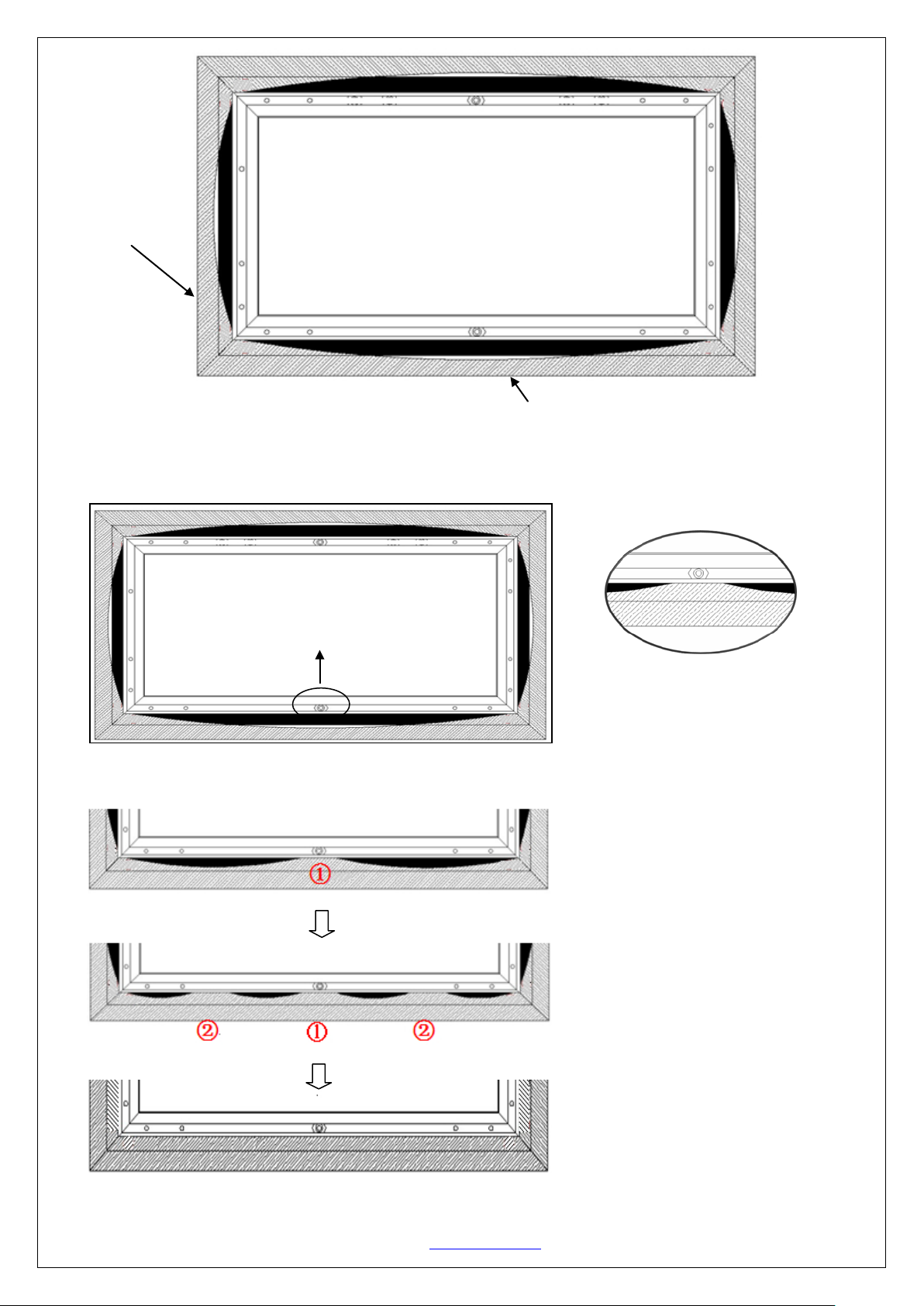
end will ultimately attach with the other velcro end on the screen mat erial.
Lay the Velcro end on the screen
①②
The key is to attach within the
Repeat the same steps on the
three sides in the
Note:
Represents the
screen material
5. Proceed to attach the rest of the material to the frame as described in the illustrations below.
Note: The black shaded part represents the velcro on the frame. That Velcro
Grasp the middle of the screen material and
attach it to the velcro strip on the fra me
material over the Velcro end of the
frame and keep it within the edge.
Proceed in the following sequence
below
middle sections of 1 and 2. Then
continue attaching the remaining
unattached areas.
Rev.041717-DR www.elitescreens.com 5
remaining
sequence A, B, C, and D as shown
below.
Page 6
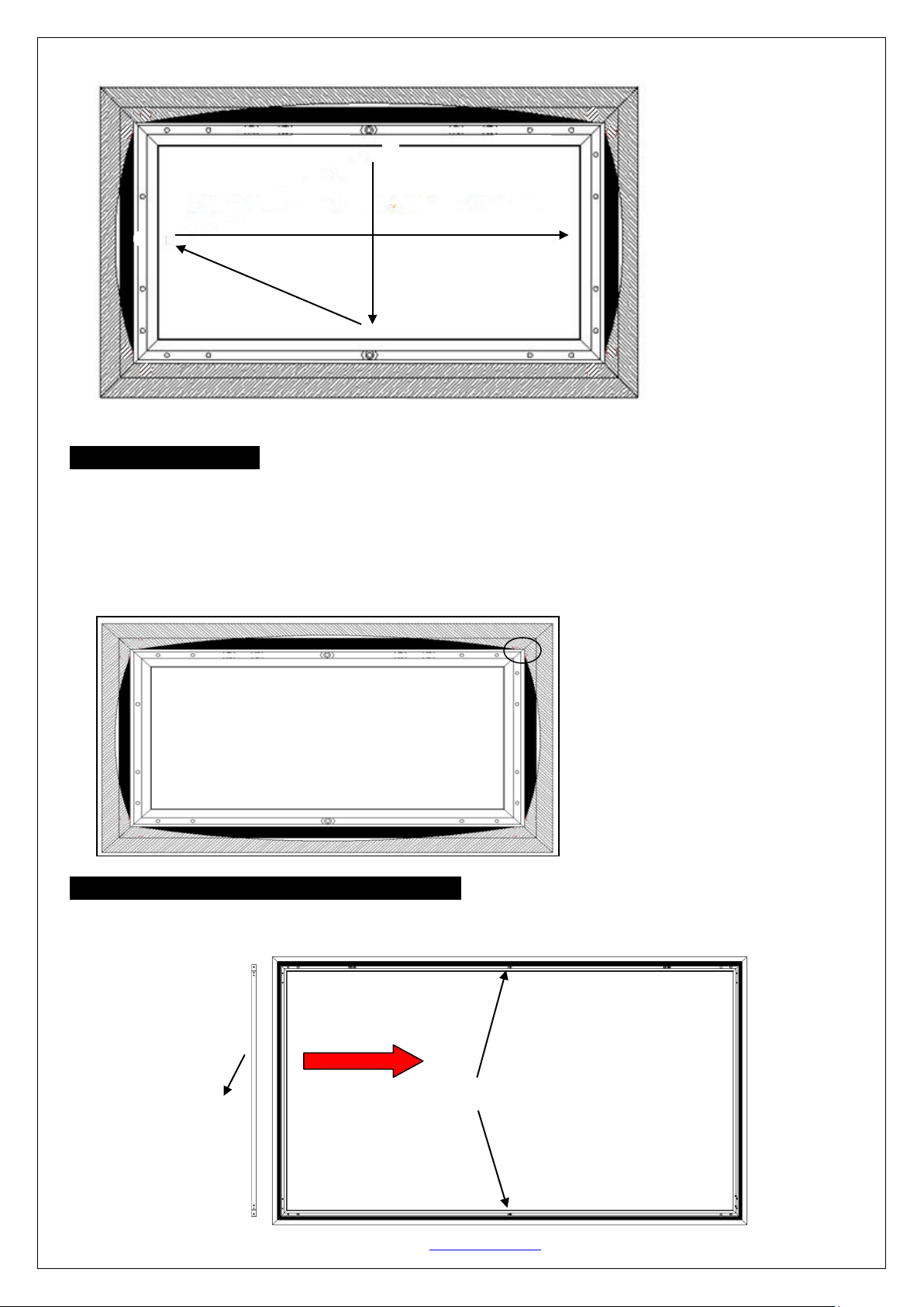
Pull back the screen material from
the velcro connection along the
Attach in the following sequence: a-b-c-d
A
B
C
Move the M6 hex screw to the middle area of the frames.
Support bar
D
Screen Material Removal
Follow the steps to properly remove the screen material from the frame. This procedure will ensure prolonging the
life of the screen material.
1. Detach the velcro from the frame.
2. Gently pull back the material to release the material from the velcro connections on the corners.
edges of the frame to detach it.
Support bar installation (for models under 135”):
1. Position the center support bar (E) in the middle of the frame and align the hole on each end of the support
bar with the M6 hex screws on the top and bottom frames. Then fasten with the M6x12 screws.
Rev.041717-DR www.elitescreens.com 6
Page 7
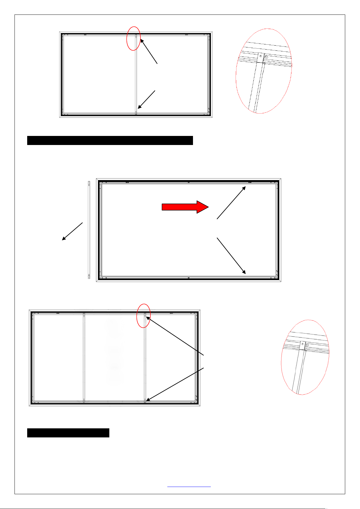
Align the M6 screws
Move the M6 hex screw to these areas of the frame.
with the two holes
Figure 1
Support bar installation (for models 135” and above):
1. Position the center support bar (E) to the area of the frame shown in figure 1. Align the hole on each end of
the support bar with the M6 hex screws on the top and bottom frames. Then fasten with the M6x12 scr ews.
with the two holes.
Center Support Bar
Align the M6 Screws
located on the Center
Support Bar .
Black Backing Installation
1. Lay the Black backing completely flat with the opening side facing down on the white (AcousticPro UHD)
material in a horizontal position under the center support bar.
Rev.041717-DR www.elitescreens.com 7
Page 8
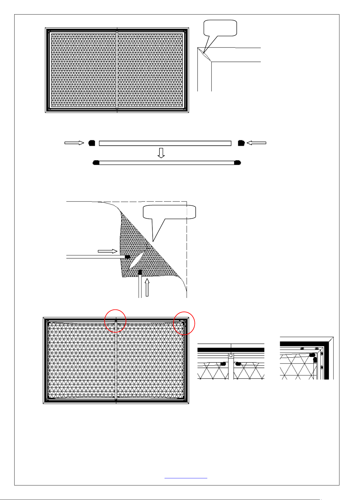
Black backing
Opening
2. Put the plastic sleeves on the fiberglass rods.
3. Insert the fiberglass rods (M) through the openings. The longer rods are used on the vertical edges of the screen
material, and the shorter rods are used on the horizontal edges, as shown below.
4. Hook installation
1) Follow steps
2)Affix the hooks on the red arrow marks (Fig. 3).
Rev.041717-DR www.elitescreens.com 8
○1○2○
3 on Fig. 1 to properly affix the hook to the frame as shown in Fig. 2.
Page 9
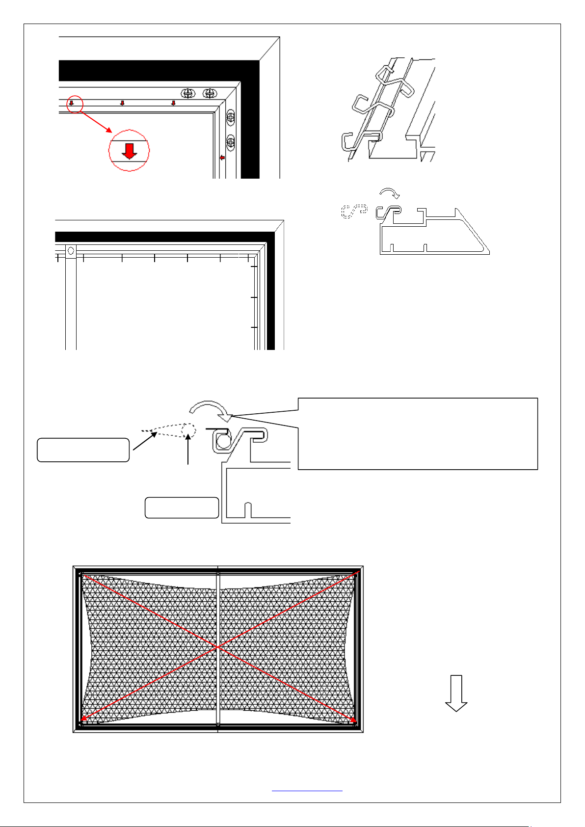
First, stretch the four corners of
the first two hooks on each
Fig.3
Black mesh backing
Fiberglass rods
A
C
D
B
Fig.1
○
3
Make sure the hooks are affixed correctly
backing once they have been affixed.
Arrow marks
2
○
1
○
5. Black backing material attachment into the hooks.
Fig.2
Example of properly affixed hook to frame.
NOTE:
as they are not easy to remove from the black mesh
Grasp the Fiberglass rod inside the black backing,
and press it into the hooks’ groove. This is the
proper method to assure the black backing has
sufficient tension.
Rev.041717-DR www.elitescreens.com 9
the black backing and insert into
corner in the following sequence
A→B→C→D.
Page 10
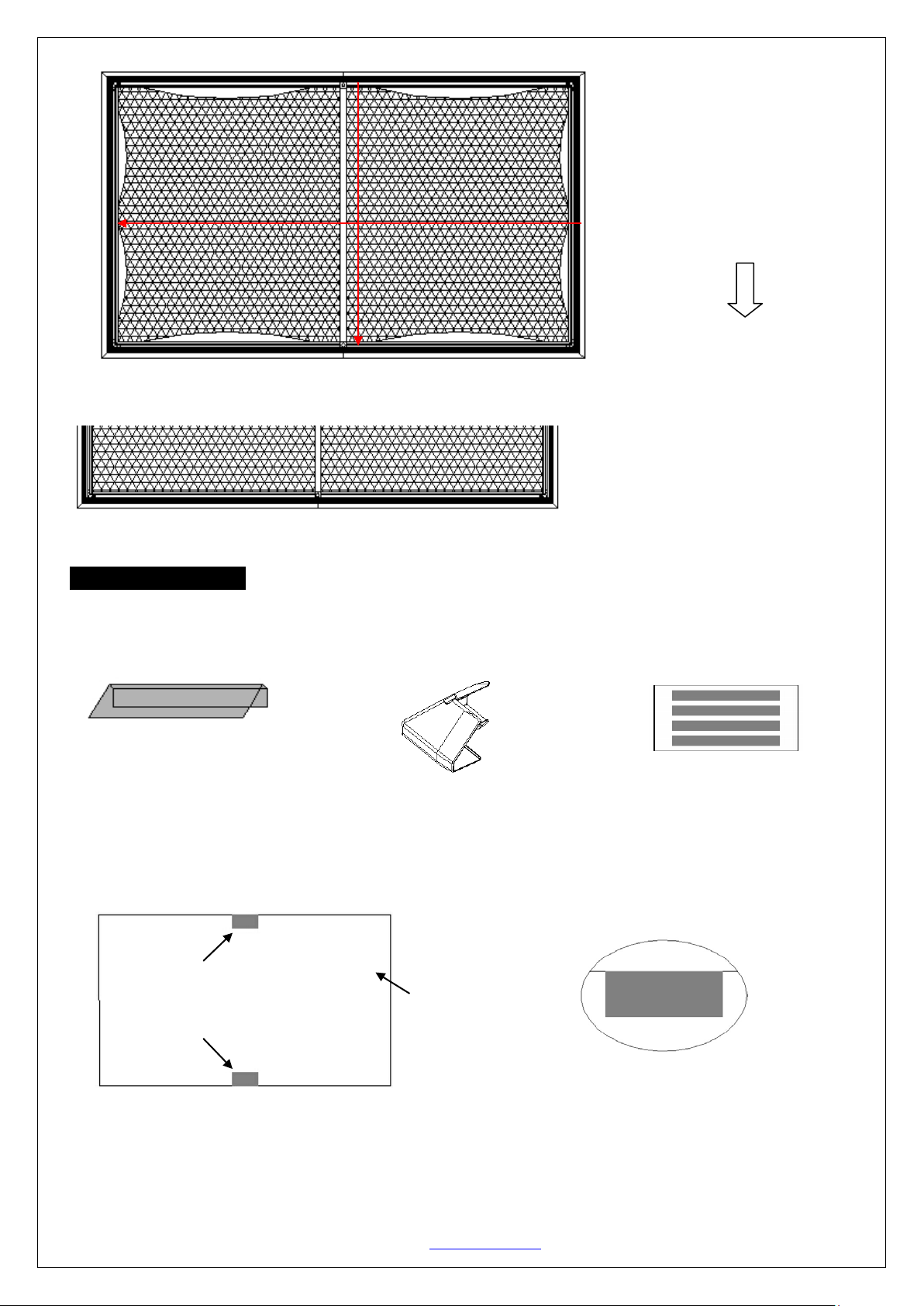
Edge trim x 6 pcs
Black tape x1bag
The black tape
the black backing
Lastly, affix the black backing to
b
d
c
Plastic corner sleeve x4pcs
Figure 1
Next, stretch
and affix to the hooks from the
middle
a→b→c→d
the remaining hooks. Add more
hooks as needed to achieve flatter
results in the areas that are not flat.
in the following sequence
Edge trim Installation
The Aeon fixed screen is EDGE FREE®, but you may install the Edge trim to provide it with an elegant thin bezel
finish.
1. Place the assembled frame on a flat and clean surface. The projection screen surface should be facing up.
a. As an option, Black Tape is supplied to cover any possible gaps between the pieces of the bezel trim.
Align the tape with the edge of the screen, as shown in Figure 1. Once properly aligned, apply the black
tape to the center of the top and bottom of the screen material.
2. Without removing the adhesive tape, place all the trim pieces along the edge of screen material. Adjust the trim
so that the top and bottom trim pieces are touching and show no gaps in the center. (Note: The Elite logo should
be positioned on the bottom right). Refer to Figure 2 below for a visual reference.
Front of screen
The black tape
Rev.041717-DR www.elitescreens.com 10
Page 11
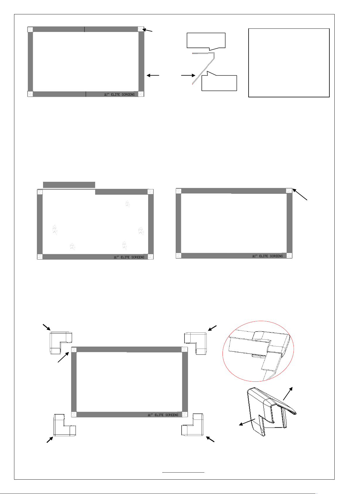
Front side
Back side
sleeves.
A
C
E
Figure 3
Figure 2
White area
signifies
corner gap.
Front Side
Trim
strip
Back Side
Align the trim starting
from the center to reduce
gapping. Any gaps left at
the corners will be
covered by the corner
TIP:
NOTE: Make sure the bottom edge trim with the Elite Screens logo is installed on the correct side. The back of
the material should be labeled with a DOWN sticker to indicate the material is facing in the down position. The
Elite Screens logo should be installed on the DOWN side
3. After properly aligning all trim pieces, carefully remove trim piece A (see Figure 3 below). Remove the inside
backing of the tape and place the trim piece in its original position on the frame. Repeat this step for the
remaining trim pieces in the following order:
B-C-D-E-F.
The front side of the frame with trim pieces attached.
F
D
Corner gap
will be
covered by
the corner
sleeve (K).
4. After the bezel trim has been installed, place a corner s leeve (K) on all four corners. Begin by aligning and
adjusting the corner sleeve through the front of the screen. Make sure the corner sleeve completely wraps the
edge of the bezel trim. This should cover any corner gaps.
White area
signifies
corner gap.
Once all corner sleeves have been snapped into each corner of the frame, it is ready to be installed.
Rev.041717-DR www.elitescreens.com 11
Page 12
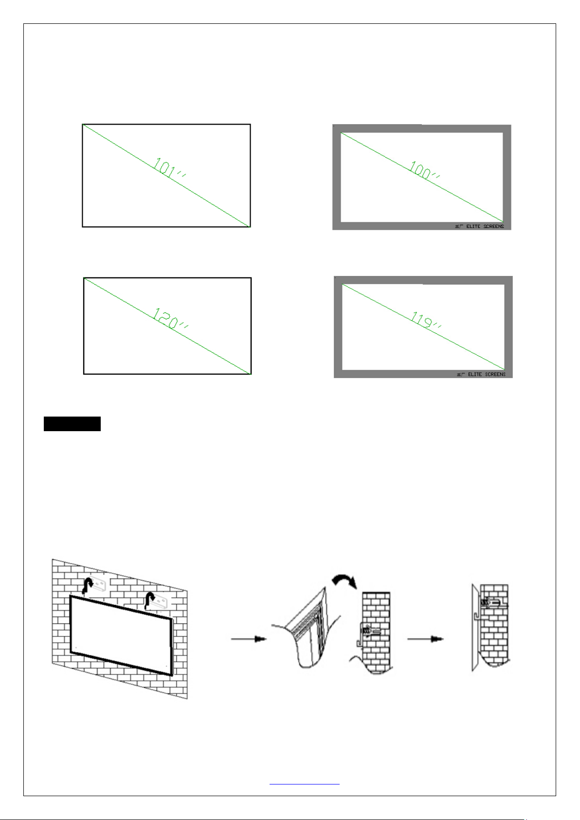
Before installing the edge trim
After installing the edge trim
After installing the edge trim
Before installing the edge trim
Attention: Installing the
comparison of the viewing size of the before and after edge trim installation using the 100” & 120” 16:9 diagonal
models.
100” comparison:
edge trim will reduce the viewing size of your screen. See below illustrations for a
120” comparison:
Installation
Locate your desired installation location with a stud finder (recommended) and mark the drill-hole area of where the
screen is to be installed.
1. Drill a hole with the proper bit size according to the wood screws included.
2. Line up the wall brackets with the drilled holes on the installation location and screw them in using a
Phillips screwdriver.
3. Position the frame screen onto the wall brackets (F) as shown in below.
4. The design of the wall brackets allows the frame to slide over them through its sides. This is an important
feature of the installation design as it allows your screen to be properly centered.
For a local Elite Screens contact or Technical Support, please visit
Rev.041717-DR www.elitescreens.com 12
www.elitescreens.com
 Loading...