

Page 1

Aeon CLR® 3
Ceiling Ambient Light Rejecting Fixed Frame Screen
USER’S GUIDE
M Type – V 1.1
____________________________________________________________________________________________
Product Description:
The Aeon CLR® 3 Series is a fixed frame projection screen that uses Elite’s EDGE FREE® technology. The EDGE
FREE® design resembles a flat panel TV display. The Aeon CLR® 3 includes a micro-thin bezel trim to further
enhance the frame appearance and absorb projector overshoot.
The screen material included is our CLR® 3, which is an optical lens front projection material precisely formulated
for environments with minimal control over room lighting. It was designed to filter and absorb overhead light while
directing table-top mounted ultra-short throw projection. It best for family rooms, educational facilities, conference
rooms or any applications in which incident light is a factor.
Screen maintenance
Dust, dirt and scratches on the projection screen surface will affect the quality and performance of the projection
image. Follow the instructions below to properly maintain the screen.
1) The screen surface has a horizontal linear structure. DO NOT wipe the screen up and down or in a circular
motion. Wipe gently from left to right only.
2) Clean the dust on the screen surface with a soft brush or microfiber cloth. A rough/coarse towel or cloth may
damage the screen’s surface.
3) Use a dry dust cleaner blower to remove any dust form the screen material.
4) Gently wipe the screen with a lightly moistened white lint free cloth with water or with a neutral detergent
(1mL/0.33 oz) mixed with water (1000 mL/33.8 oz).
Notes: The following precautions should always be followed to avoid damaging the material, which is
not covered under warranty.
• Don’t touch the screen material to avoid leaving fingerprints.
• Use gloves when handling the material.
• Don’t scratch the material, as it will leave permanent markings on the screen’s surface.
• Don’t point to the screen material with a fingertip or other sharp objects to prevent damage to the material.
• Don’t use acetone, benzene, alcohol and any other organic solvents to clean the screen material. Using such
chemicals will permanently damage the screen.
Page 2
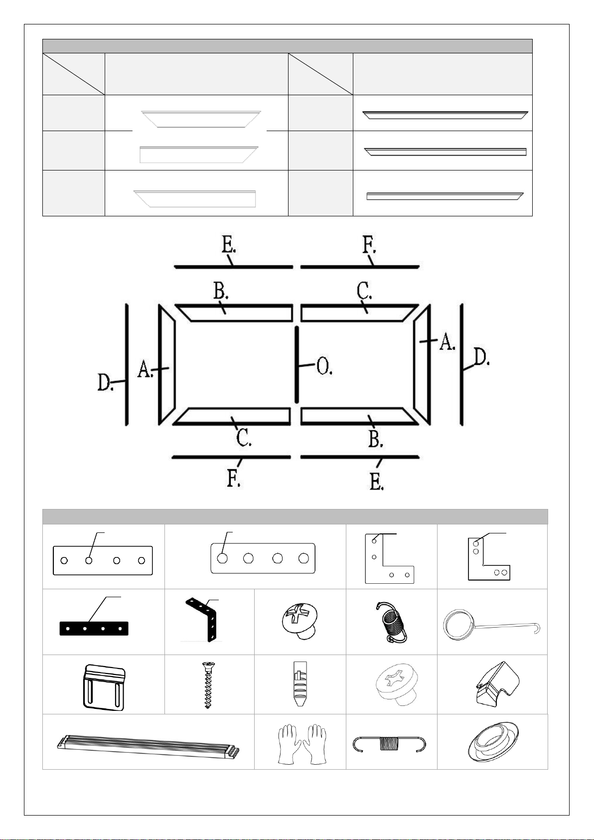
Item
Part A.
Part B.
Part C.
Qty
1. Frame and Edge Trim Parts List
2 pcs
Main Frame Parts
vertical frame
½ horizontal frame
½ horizontal frame
Qty
item
Edge Trim Parts
Part D.
Part E.
2 pcs
Part F.
2. Hardware Parts List
a. M4*4 b. D5*4 c. M4*4 d. D5*4
e. M4*4 f. M4*4 g. h. i.
j. k. l. m. n.
o. p. q. r.
06072022JA U-00202 2
Page 3
Item Parts List
a. Center Joints- M4 (bottom position) 2 2 2
b. Center Joints-D5 (top position) 2 2 2
c. Elbow Joints M4 (bottom position) 4 4 4
d. Elbow Joints D5 (top position) 4 4 4
e. Side cover Center Joints- M4 2 2 2
f. Side cover Elbow Joints M4 4 4 4
g. M4x7 Screws 24 24 24
h. Spring 88 100 104
i. Spring Hook 2 2 2
j. wall brackets 4
k. Φ5x50 Wall Screws 8 8 8
l. Hollow Wall anchors 8 8 8
m. M4x4 Screws 24
n. Angle cover 4
o. Center Support Bar 1 1 1
p. White gloves 2 2 2
q. Spring 4 4 4
r. Iron eyelet 88 100 104
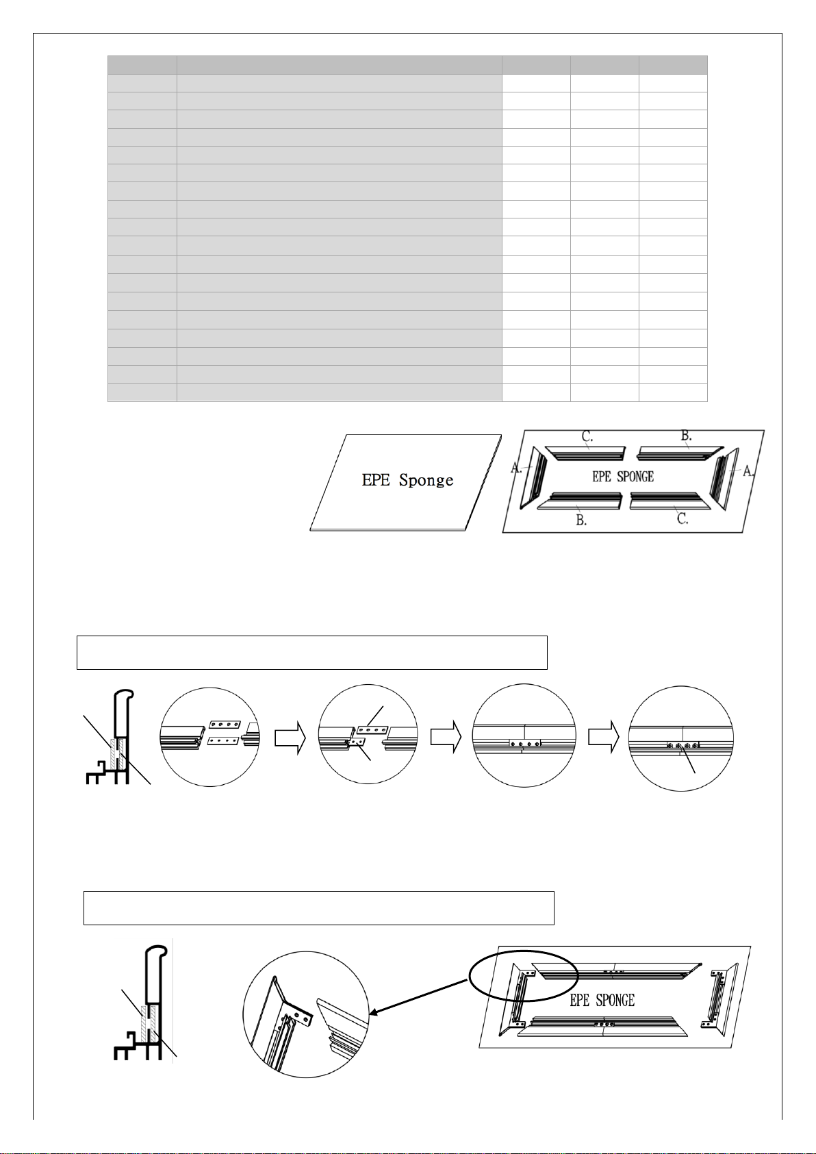
Frame Assembly
Step 1: Place the included soft padded
103'' 115’’ 123’’
4
24
4
4
24
4
EPE sponge sheet on a clean area where
the screen will be assembled.
Step 2: Position the pieces of the frame
on the EPE sponge in the arrangement
shown above.
Step 3: Insert center joint (a/b) connectors into one-half of the horizontal frame (B/C) and secure with the M4x7
screws (M) as shown in the illustration below.
Tip: The center joint (b) with the larger diameter holes should be on top.
b.
b.
a.
g.
Step 4: Connect the elbow joints (c/d) to the top and bottom sections of the vertical frame. Once inserted, connect
the vertical sections to the horizontal frame sections. Make sure all holes are in alignment and the frame pieces are
flush (no gaps). They should form perfect right angles.
a.
Tip: The elbow joint (d) with the larger diameter holes should be on top.
d.
c.
Page 4
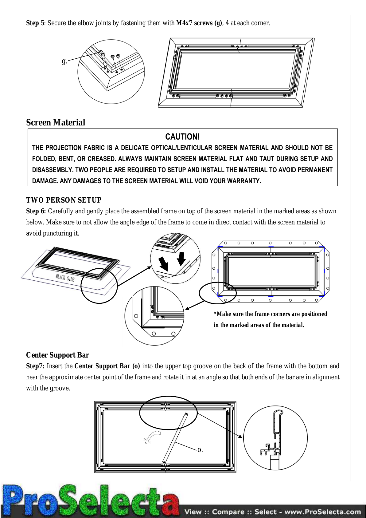
Step 5: Secure the elbow joints by fastening them with M4x7 screws (g), 4 at each corner.
in the marked areas of the material.
g.
Screen Material
THE PROJECTION FABRIC IS A DELICATE OPTICAL/LENTICULAR SCREEN MATERIAL AND SHOULD NOT BE
FOLDED, BENT, OR CREASED. ALWAYS MAINTAIN SCREEN MATERIAL FLAT AND TAUT DURING SETUP AND
DISASSEMBLY. TWO PEOPLE ARE REQUIRED TO SETUP AND INSTALL THE MATERIAL TO AVOID PERMANENT
DAMAGE. ANY DAMAGES TO THE SCREEN MATERIAL WILL VOID YOUR WARRANTY.
TWO PERSON SETUP
Step 6: Carefully and gently place the assembled frame on top of the screen material in the marked areas as shown
below. Make sure to not allow the angle edge of the frame to come in direct contact with the screen material to
avoid puncturing it.
CAUTION!
*Make sure the frame corners are positioned
Center Support Bar
Step7: Insert the Center Support Bar (o) into the upper top groove on the back of the frame with the bottom end
near the approximate center point of the frame and rotate it in at an angle so that both ends of the bar are in alignment
with the groove.
o.
Page 5
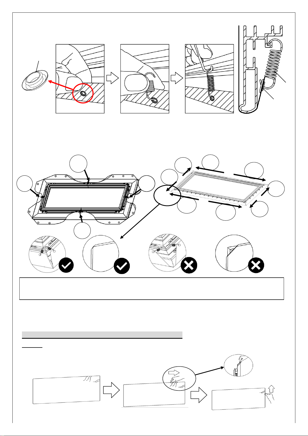
Step 8: 1. Insert iron eyelet through the CLR® 3 material hole from behind.
2. Attach the spring into the iron eyelet.
3. Use the spring hook tool to attach the other side of the spring on the frame.
r.
r.
Begin by first attaching the center points on both vertical (left/right) sides, steps 1-2. Then the center points on both
horizontal (top/bottom) sides, steps 3-4. Once all center points have been secured, make sure the screen material is
still within the marked areas before proceeding to attach the next springs. Continue attaching the rest of the springs
to the material in the following order in steps 5-12.
3
5
9
11
7
1
2
6
h.
4
10
12
8
To avoid ripples forming in the material it is imperative that all of the corners are properly wrapped around the
edges as illustrated in the check mark diagrams.
Note (after all springs have been attached):
Correct material installation –Corners of the screen material are properly wrapped around the corner edges of the
frame and material is evenly tensioned and flat, creating a nicely taut surface.
How to avoid getting ripples on the screen’s material surface
Solution: With the gloves on and assuring they are clean, pull and smooth out the material using your hand from
the center to the corners, creating a nicely taut surface as shown below.
Page 6
Incorrect material installation –The corners of the screen material are not properly wrapped along the edge of the
frame leaving the material with unbalanced tension and an uneven finish. To correct, detach springs from material at
the corner(s) where material does not lie flat along the edge of the frame, reposition the material so that it lies flat
and wraps along the edge of the frame, and reattach springs to the material.
Attention: Do not proceed with the Edge Trim installation until making sure there are no ripples in the material.
Edge Trim Installation
ATTENTION: The back of the material has labels indicating the TOP and BOTTOM. The top edge trim piece with the
logo should be installed at the top. The material is directional and will not accurately reflect if bottom side is projected on.
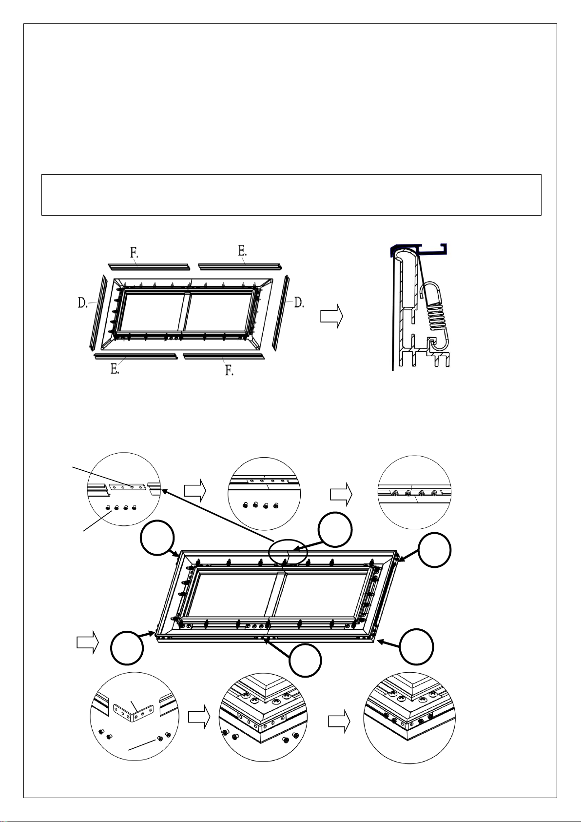
Step 9: Place the edge trim frame pieces over each end of the frame.
Connect edge trim frames (e/f) together using the M4 center joint (e) and secure with four of the M4x4 screws (m)
as show in Step 1. Repeat for other side.
Once both top and bottom edge trim frames have been connected, attach the vertical (left/right) sides edge trim
frames (d) using the elbow joints (f) and secure with four M4x4 screws (m) on all corners, Step 2.
e.
m
2
1
2
2
1
f.
2
m
06072022JA U-00202 6
Page 7
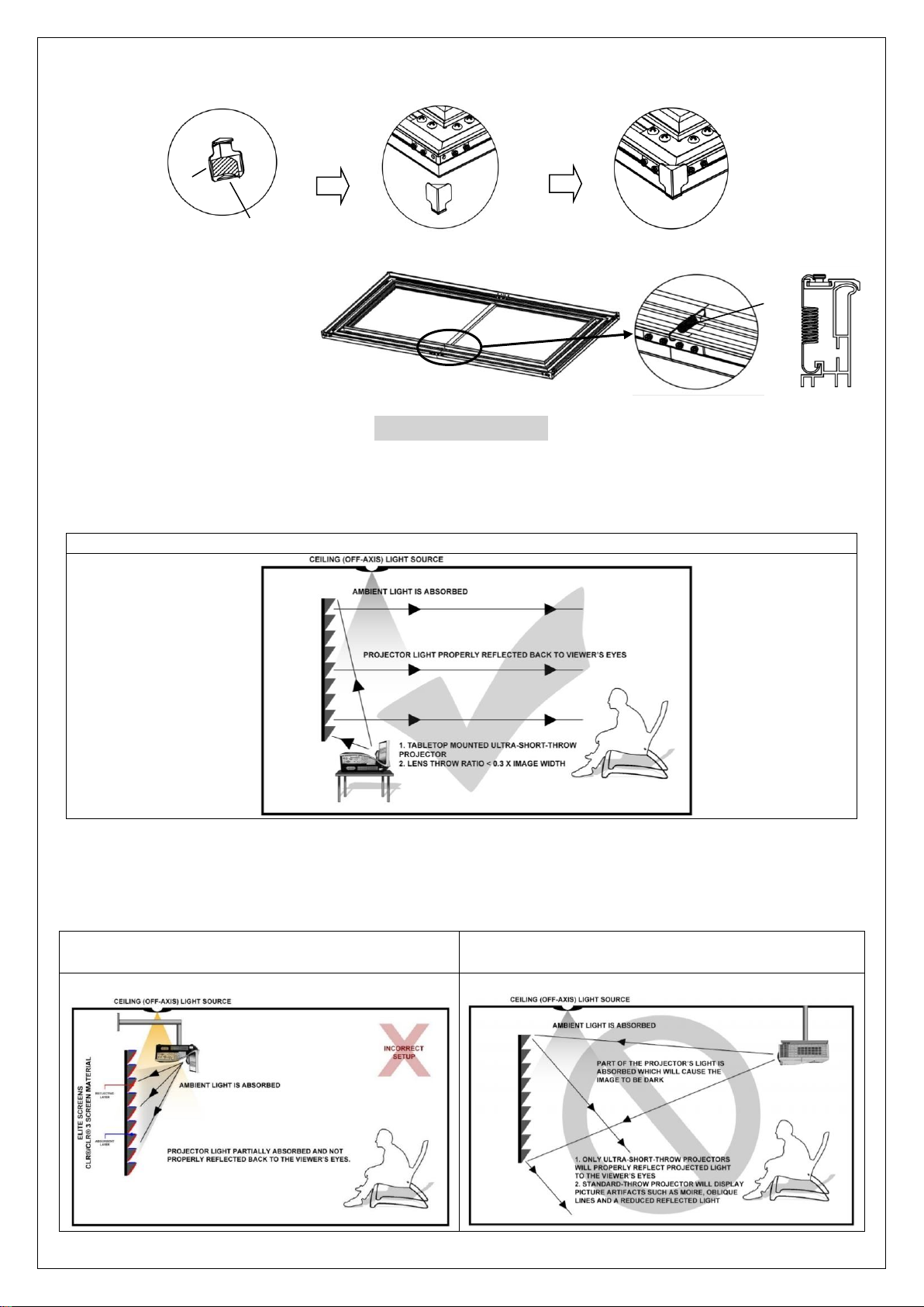
Step 10: Install the angle cover (n) on each corner of the frame using the M4x4 screws (m).
Note: The angle cover screws holes align with the screw holes on the elbow joint.
n.
Step 11: Install the springs (q) in
each middle area to further support
the bezel trim edge frame.
Peel off the double-sided tape.
Notice to Installer:
Proper Projector Placement for CLR
The CLR® 3 is exclusively for table-mounted ultra-short throw projectors.
PROPER PROJECTOR PLACEMENT
Tabletop (bottom) mounted ultra-short throw projector illustration
®
3
q.
IMPROPER PROJECTOR PLACEMENT
Overhead placement or a standard projector will make the image very dark, on account of the screen’s absorbent
layer deflecting light that is not aligned with its reflective angle.
Ceiling mounted ultra-short throw projector
illustration
06072022JA U-00202 7
Ceiling Mounted Short and Standard-Throw
Projector illustration
Page 8
Wall Installation
j
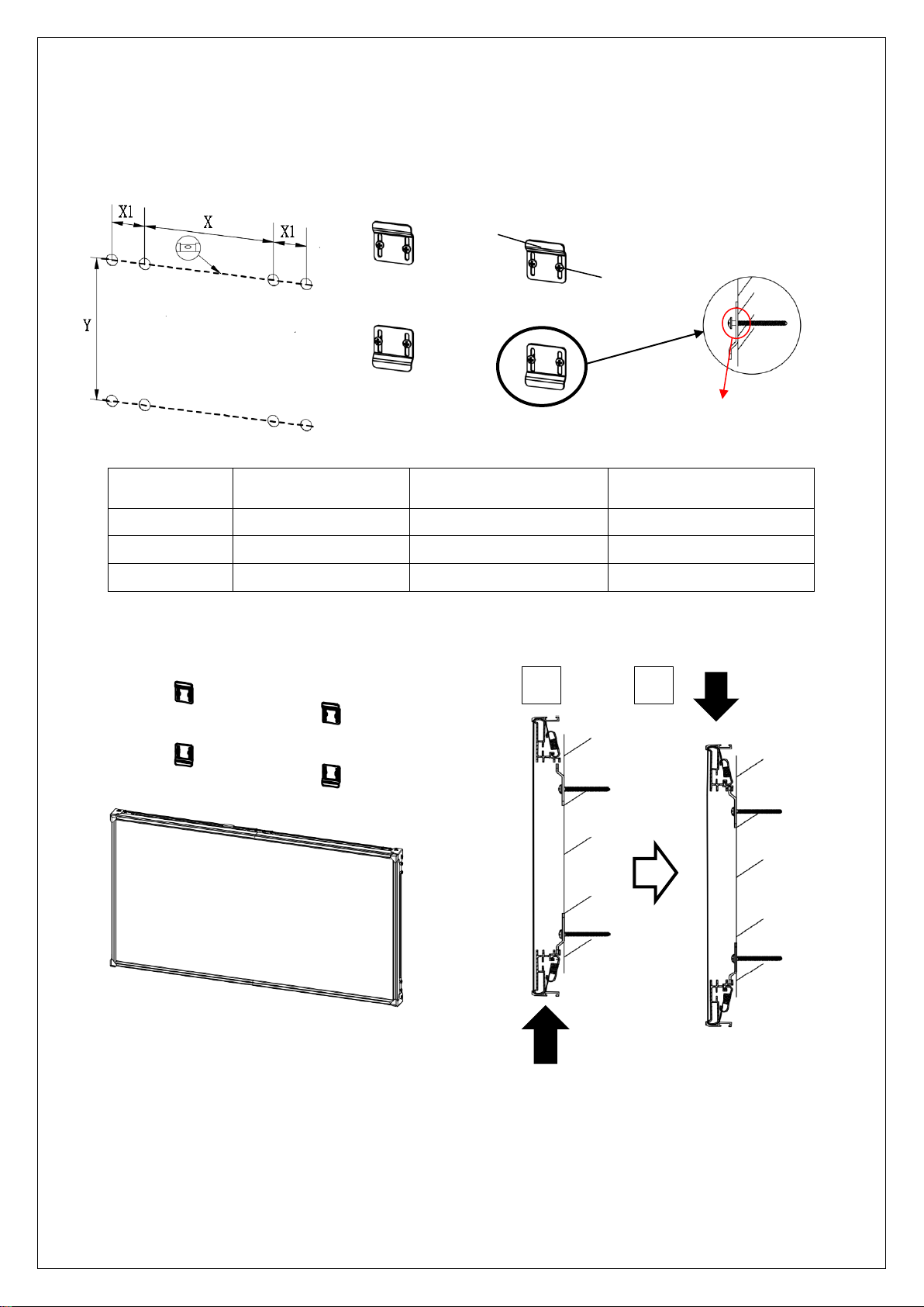
Step 12: Measure the overall length and height of the frame and drill holes for the top brackets. Line up the wall
brackets with the drilled holes on the installation location and screw them in using a Phillips screwdriver. If not
installing into a structural wood stud, use a hollow wall anchor then screw in the M5x50 wood screws with a
screwdriver. Make sure the brackets are leveled.
.
k.
Don’t tighten the screw to allow the
Step 14: Position the fixed frame screen onto the top wall brackets (fig 1) as shown below and push down
Model/Size X = Wall bracket
distance
103'' 1200mm (47.24'') 30mm (1.18'') 1110mm (43.7'')
115’’ 1300mm (51.18'') 30mm (1.18'') 1270mm (50'')
123’’ 1400mm (55.12'') 30mm (1.18'') 1360mm (53.54'')
X1 = Bracket hole
distance
screen to move up and down.
Y = Top/Bottom Wall
Bracket Height
at the center of the top of the frame (fig 2) to secure.
1
2
For Technical Support or an Elite Screens contact in your area, visit
www.elitescreens.com
06072022JA U-00202 8
 Loading...