

ELiSS LD-1600 User Manual
LeadTech Crop.
16CH Color Digital Video Recorder
USER MANUAL
ELiSS LD-1600

Linux DVR System
Copyright
ⓒ 2003 LeadTech Corp. All rights reserved.
LeadTech
2
The contents of this User’s Manual shall not be reproduced arbitrarily without prior
approval.
The product of this User’s Manual may be modified without advance notice for the
reasons of upgrading, etc.
The trademarks mentioned in this User’s Manual are registered trademark and unique
trademark of each relevant company.
Please contact LeadTech Corporation for any unclear matters or errors to be corrected
in the contents of this User’s Manual.
Introducing DVR (Digital Video Recorder)
The D.V.R. (Digital Video Recorder) system which overcomes weak point of conventional
CCTV system where there inconvenient to operate with lots of restrictions.
DVR system converts and records video images from conventional analog CCTV camera
for extended period of time with real-time surveillance.
DVR systems, not like conventional CCTV system which just records incoming video
images but single DVR system can be incorporated with various external components (ex.
Thermal Detector, Infrared Sensor, Shock Sensor, Door Sensor, light, access control and
etc.) and self contained Motion detection feature which is with no doubt most integrated
surveillance system ever.
Especially, now a days not like systems from the past which operates independently from
each other Number of systems incorporates as an network which makes unified system
management and surveillance possible and also where there is internet access available
it can be viewed and controlled from remote places in real-time. To construct networks of
surveillance system requires DVR system which is a must.
FCC ID No. : P8ZSECUMESH400
This device complies with part 15 of the FCC Rules.
Operation is subject to the following two conditions:
(1)This device may not cause harmful interference, and (2) this device must accept any
interference deceived, including interference that may cause undesired operation.

Linux DVR System
This User’s Manual contains the following contents.
Matters to note in installing ELiSS LD-1600
Name and function of each part of ELiSS LD-1600
Method of installation of ELiSS LD-1600 and connection of related
equipment
Method of using and setting of ELiSS LD-1600
Product specifications of ELiSS LD-1600
Repair of trouble and checking procedures, etc. of ELiSS LD-1600
The users who handle ELiSS LD-1600 are requested to pay attention to the matters to be
noted after reading the User’s Manual prior to its use.
LeadTech
3

Linux DVR System
Contents of User’s Manual
I . MATTERS TO BE NOTED.......................................................................................................9
II . COMPOSITION OF ELISS LD-1600 PRODUCT ...............................................................10
III . MAJOR FEATURES OF ELISS LD-1600.......................................................................... 11
IV . FUNCTION OF ELISS LD-1600........................................................................................ 12
V . NAME AND FUNCTION OF EACH PART OF ELISS LD-1600.........................................14
1. Name and Function of Each Part of Front Operating Panel ..........................................14
2. Name and Function of Each Part of Rear Side Connection Terminal ........................... 15
VI . METHOD OF INSTALLING ELISS LD-1600 ....................................................................16
1. Composition Drawing of Entire Rear Side....................................................................... 16
VII . METHOD OF USE OF ELISS LD-1600 ...........................................................................17
1. Power ON/OFF of ELiSS LD-1600 .....................................................................................17
2. DISPLAY MODE(Monitor Mode) ........................................................................................18
2.1. Explanation of DISPLAY MODE Screen........................................................................ 18
( Refer to p. Change of screen division.) .................................................................................... 18
2.2. Explanation of Contents Displayed on Each Screen (The case when OSD setting is ON)
..............................................................................................................................................19
2.3. Conversion to Display Mode from Other Mode .............................................................20
2.3.1. Conversion to Display Mode from Search Mode.................................................................20
2.3.2. Conversion to Display Mode from Setup Mode...................................................................20
2.3.3. Conversion to Display Mode from PTZ MODE...................................................................20
2.4. Change of Screen Dividing from Display Mode............................................................. 21
2.5. Automatic Channel Switching Function and TV OUT.................................................... 22
2.6. Conversion of Camera Channel from DISPLAY MODE Screen.................................... 22
LeadTech
4

Linux DVR System
2.7. Conversion of camera channel from DISPLAY MODE screen...................................... 22
2.7.1. Conversion of Camera Channel from Screen Divided into 9 ...............................................23
2.7.2. Conversion of Camera Channel from Screen Divided into 8 ...............................................24
2.7.3. Conversion of Camera Channel from Screen Divided into 4 ...............................................25
2.7.4. Conversion of Camera Channel from Full Screen................................................................26
2.8. Real Time Storage in DISPLAY MODE .........................................................................27
3. SEARCH MODE(RETRIEVAL MODE)................................................................................28
3.1. Explanation of Search Mode (RETRIEVAL MODE) Screen.......................................... 28
3.2. General Search.............................................................................................................. 29
3.2.1. Method of General Search....................................................................................................29
3.2.2. Regeneration of Generally Searched Data............................................................................30
3.2.3. Explanation of Data Regeneration Scr een............................................................................30
3.2.4. Explanation of Contents Displayed on Each Regeneration Screen ......................................31
3.2.5. Change of Screen Division of Search Mode.........................................................................32
3.2.6. Conversion of Camera Channel from Search Mode.............................................................33
3.2.7. Explanation of Regenera t i on Fu nct i o n B ut t on.....................................................................34
3.3. Event Search .................................................................................................................35
3.3.1. Explanation of Event Search Screen.....................................................................................35
3.3.2. Method of Event Search .......................................................................................................36
3.3.3. Regeneration of Event-Searched Data..................................................................................37
3.3.4. Data Regeneration Screen ....................................................................................................37
3.3.5. Search of Other Date from Event Search Screen..................................................................37
3.4. SEARCH MODE-JPEG BACKUP .................................................................................38
VIII . BACKUP OF STORED DATA .........................................................................................39
1. Explanation of Backup Initial-Screen............................................................................... 40
2. Explanation of Backup Progress Screen......................................................................... 41
3. Explanation of Backup Method of Stored Data ...............................................................43
3.1. Explanation of Backup Method with LDV Extension .....................................................43
3.2. Explanation of Backup Method with AVI Extension....................................................... 45
3.3. Method of Regeneration of Data in USB Hard disk in ELiSS DVR ...............................48
IX . SETUP METHOD OF ELISS LD-1600..............................................................................50
LeadTech
5

Linux DVR System
1. Setup Mode .........................................................................................................................50
2. Input of Admin’s Password ...............................................................................................50
2.1. Explanation of Admin’s Password Input Screen............................................................ 50
2.2. Method of Password Input............................................................................................. 51
2.3. Conversion to Other Screen .......................................................................................... 52
3. Setup Mode Initial-Menu Screen....................................................................................... 53
3.1. Explanation of Setup Mode-Initial Menu Screen ...........................................................53
3.2. Selection of Menu from Setup Mode .............................................................................54
4. Setup Mode – General Setup.............................................................................................55
4.1. Setup Mode – Explanation of General Setup Screen.................................................... 55
4.2. Setup Mode – Selection of General Setup Menu .......................................................... 56
4.3. Changing Password.......................................................................................................57
4.4. Channel Switching Setup and TV OUT .........................................................................58
4.5. OSD Setup..................................................................................................................... 59
4.6. Setup of Rebooting ........................................................................................................ 60
4.7. Date Setup..................................................................................................................... 61
4.8. Movement to Initial Menu Screen of Setup Mode from General Setup Screen ............62
5. Setup Mode – Camera Setup............................................................................................. 63
5.1. Setup Mode – Explanation of Camera Setup Screen.................................................... 63
5.2. Setup Mode – Designation of Camera from Camera Setup Initial-Screen....................64
5.3. Changing Camera ID ..................................................................................................... 65
5.4. Setup of Frame Rate .....................................................................................................66
5.5. Setup of Video type .......................................................................................................67
5.6. Setup of PTZ Type / ID ..................................................................................................68
5.7. Setup of the Status of Recording................................................................................... 69
5.8. Setup of Motion.............................................................................................................. 70
5.8.1. Setup of Motion Sensitivity..................................................................................................70
5.8.2. Setup of Motion Continuance Time......................................................................................71
5.8.3. Setup of Motion Sphere Displ ay ...........................................................................................71
5.9. Setup of Compressed Image Quality.............................................................................72
5.10. Setup of Alarm ............................................................................................................. 73
5.11. Setup of Resolution...................................................................................................... 74
5.12. Movement to Initial Menu Screen of Setup Mode from Camera Setup Screen ..........75
LeadTech
6

Linux DVR System
6. SETUP MODE-Color setup ................................................................................................76
6.1. SETUP MODE-Explanation of Color Setup Screen ......................................................76
6.2. Explanation of Color Setup Method...............................................................................77
7. SETUP MODE – Motion Recording Setup........................................................................ 78
7.1. Motion Recording........................................................................................................... 78
7.1.1. Execution of Motion Recordi n g...........................................................................................78
8. SETUP MODE – Motion Recording Sphere Setup...........................................................81
8.1. Explanation of Motion Sphere Setup Screen.................................................................81
8.2. Setup Method of Motion Sensing Sphere...................................................................... 82
8.3. Movement to Initial Menu Selection Screen of Setup Mode from Motion Setup........... 85
Screen................................................................................................................................... 85
9. SETUP MODE – Schedule..................................................................................................87
9.1. SETUP MODE – Explanation of Schedule Screen........................................................87
9.2. SETUP MODE – Designation of Camera at Schedule Setup Screen........................... 88
9.3. Method of Schedule Setup ............................................................................................89
9.4. Setup of Application Scope of Schedule........................................................................91
9.5. Movement from Schedule Setup Screen to Initial Menu Selection Screen of SETUP
MODE.
..................................................................................................................................91
10. SETUP MODE – Network Setup ......................................................................................92
10.1. SETUP MODE-Explanation of Network Setup Screen................................................92
10.2. Setup of DHCP (Method of IP Address Setup)............................................................ 93
10.3. Change of IP Setup Value ...........................................................................................94
10.4. Change of Net Mask Setup Value ...............................................................................95
10.5. Change of Gateway Setup Value ................................................................................96
10.6. Change of Port Setup Value ........................................................................................97
10.7. Change of Setup Value of the Number of Simultaneous Users ..................................98
10.8. Change of Setup Value of Network Image quality....................................................... 99
10.9. Movement to Menu Selection Initial-Screen of Setup Mode from Network Setup Screen
.......................................................................................................................................... 100
11. SETUP MODE – Sensor Setup..................................................................................... 101
11.1. SETUP MODE-Sensor Setup Screen...................................................................... 101
11.2. Method of Designation of Sensor Intended to Set up.............................................. 102
LeadTech
7

Linux DVR System
11.3. Change of Setup in Sensor Menu............................................................................ 103
11.4. Setup of Recording Continuance Time.................................................................... 104
11.5. Setup of Recording (Camera).................................................................................. 105
11.6. Alarm Setup.............................................................................................................. 106
11.7. Movement to Menu Selection Initial-Screen of Setup Mode from Sensor Setup Screen
.....................................................................................................................................…..106
12. SETUP MODE – Alarm Setup....................................................................................... 108
12.1. Explanation of Alarm Setup Screen......................................................................... 108
12.2. Designation of Alarm to be Set up ........................................................................... 109
12.3. Change of Setup in Alarm Menu.............................................................................. 110
12.4. Setup of Alarm Continuance Time........................................................................... 111
12.5. Movement to Menu Selection Initial-Screen of Setup Mode from Alarm Setup Screen…
.......................................................................................................................................... 111
13. SETUP MODE – Parallel Port Setup............................................................................ 113
13.1. Explanation of Parallel Port Setup Screen .............................................................. 113
13.2. Method of Parallel Port Setup.................................................................................. 114
14. PTZ CONTROL MODE.................................................................................................. 115
14.1. Explanation of PTZ Control Mode Screen............................................................... 115
14.2. Selection of PTZ Control Mode Menu ..................................................................... 116
14.3. PTZ Camera Control Method .................................................................................. 117
14.3.1. Control of PAN/TILT......................................................................................................117
14.3.2. Control of ZOOM...........................................................................................................117
14.3.3. Control of FOCUS..........................................................................................................118
14.3.4. Control of LIGHT...........................................................................................................118
14.3.5. Control of Power............................................................................................................ 119
X . PRODUCT SPECIFICATIONS FOR ELISS LD-1600.................................................... 120
XI . TROUBLESHOOTING GUIDE...................................................................................... 121
X . QUALITY WARRANTY .................................................................................................. 123
LeadTech
8

Linux DVR System
I . Matters to be Noted
Matters to be Noted
Turn off the power of EliSS LD-1600 without fail before the installation.
The persons other than professional installer should not open the cover of the case of
this product at their own discretion. When verifying internal part of this product for
system upgrade or repair of trouble, please ask to the place of purchase without fail.
When installing this product, maintain approximately 15cm of distance from other
nearby equipment.
Be careful not to apply impact or shaking when ELiSS LD-1600 is moved or in
operation.
Do not install at the place where there is strong magnetism or radio wave.
surface of wall for smooth radiation of heat. Be attentive no conductive material is put
inside the cooling ventilation hole.
Please avoid installing at the places of high temperature such as nearby direct
sunlight or heater.
Please avoid installing at the places where are extremely cold or highly humid.
Before connecting the power, check the using power of AC100~240V 50/60Hz without
fail.
This unit is designed for indoor use. Operating ambient temperature must not range
beyond (0℃~+40℃)
LeadTech
9
Linux DVR System
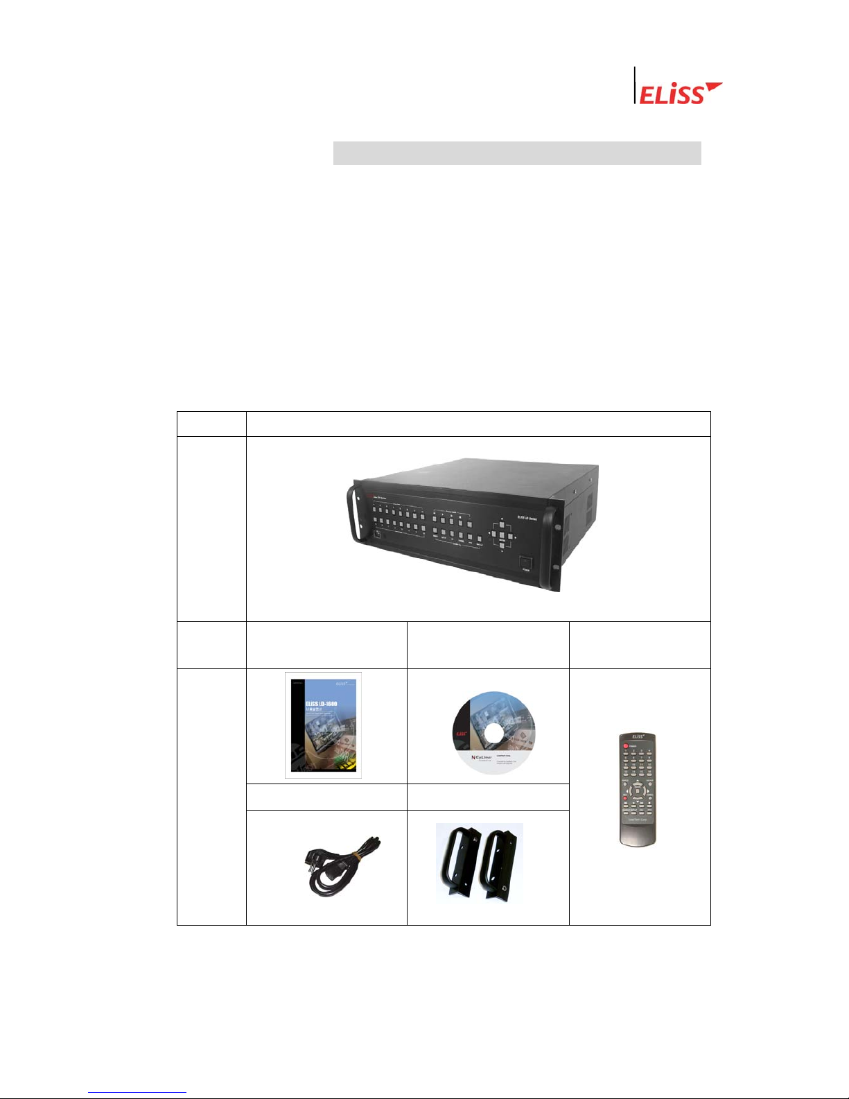
II . Composition of ELiSS LD-1600 Product
Unpack the packaging of ELiSS LD-1600 and place ELiSS LD-1600 at the place to install.
(Refer to installation safety information before the installation.)
Check the contained material of the product before the installation.
- Main body (ELiSS LD-1600)
- User’s Manual
- Ac power cable for use with ELiSS
- ELiSS CASE Handle
- EyeLinker program CD (Option)
-
Remote Control
Contents
Main composition of ELiSS DVR
External
feature of
product
Contents
User’s manual
Network Client
S/W CD(option)
Remote Control
Power cable ELiSS CASE handle.
External
view of
products
※ Since EyeLinker program CD is an optional item, it may not be contained in the contents of the package.
LeadTech
10

Linux DVR System
III . Major Features of ELiSS LD-1600
1. Accepted all merits of Window type DVR and Stand-Alone
type DVR/removed demerits
1.1. Easiness of Operation
Since the product is operated by button panel without using keyboard/mouse, the
operating system is simple and intuitive, and anyone can easily operate.
1.2. Outstanding Stability
As a Linux-based system, it could be bootable by flash memory instead of HDD, and the
product is very stable. Since the Boot-Up time is very short, all booting works are
completed within 4~50 seconds, and start capture. Its Boot-Up speed is similar to that of
ordinary times and it recovers date through journaling even during the disasters such as
sudden power failure or shutdown, etc.
1.3. Strong Network Function
Remote monitor and control is possible using exclusive Client Program.
1.4. Variety of Customizing Function
1.5. Convenient Upgrade
When only flash memory is changed, future upgrade to new version is easy.
2. Monitor
Divided monitor by each 8CH camera channel, movement monitor function, movement
storage sphere setting function are possible, and storage by time band (schedule storage),
multi resolution support, etc.
3. Search
Preceding Play, Stop, Fast Forward, Fast Backward, by each 1frame, jump search by
each 5 minute to forward and backward, event search, etc.
4. Setup
Setup by each of 16 cameras, storage schedule setup, network setup, setup by each
sensor, setup by each alarm, etc.
5. Use of Self-developed XMB Codec (MPEG4 base)
When recorded at almost similar screen quality level with actual screen, it shows
compression function as excellent as an average of about 2KB per each 1 frame.
LeadTech
11
Linux DVR System
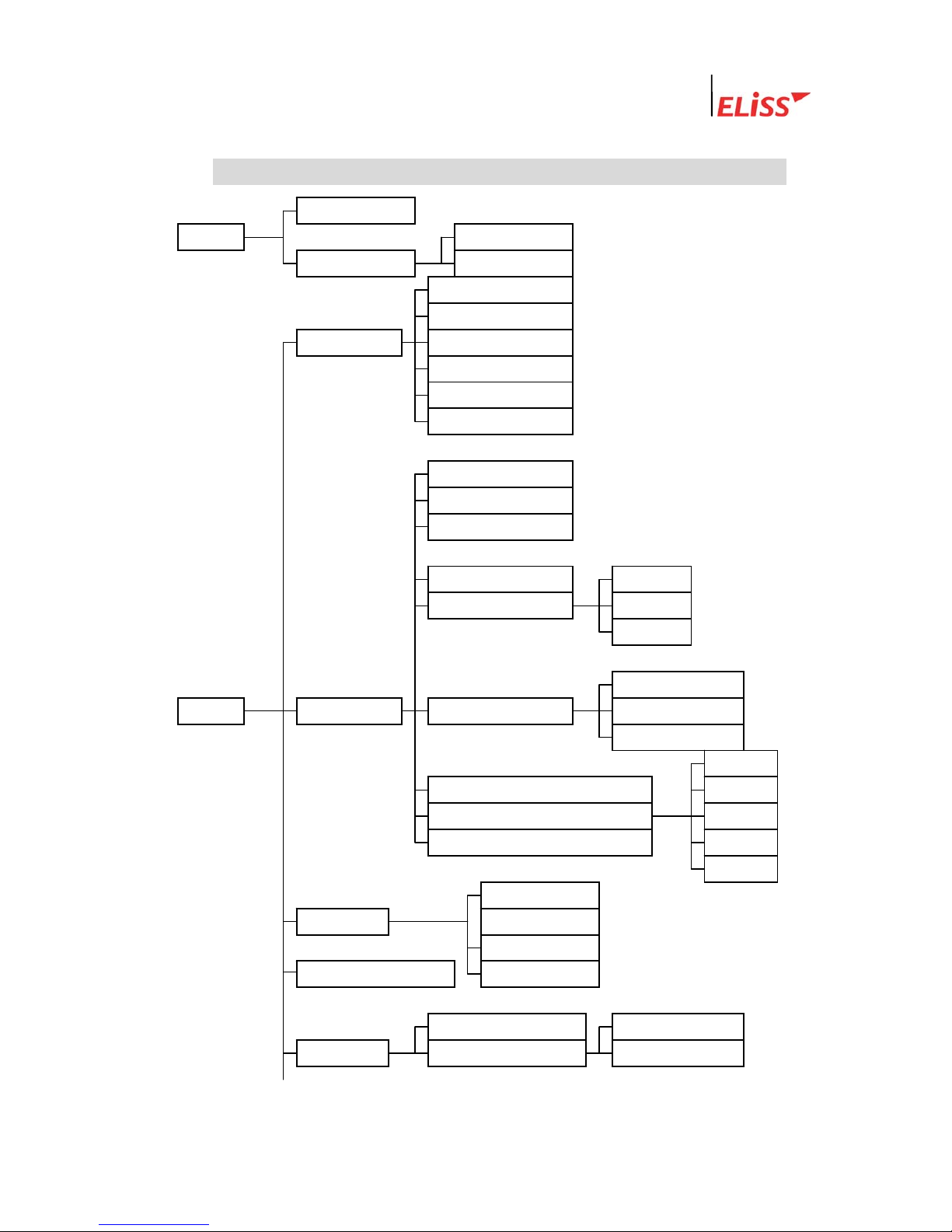
IV . Function of ELiSS LD-1600
Overlay Mode
* MODE General search
Search Mode Event search
Password
Password re-setup
General setup Channel switching
OSD
Rebooting
Date setup
ID (Camera No)
Frame rate
Storage status
LeadTech
12
PTZ type/ID Storage
Storage status Schedule
Not stored
Sensitivity setup
* SETUP Camera setup Motion setup Continuous time
Display
ALARM 1
Compression Image Select up to 1~5) ALARM 2
Alarm ALARM 3
Resolution ALARM 4
OFF
BRIGHTNESS
Color setup CONTRAST
SATURATION
Motion sphere setup HUE
Schedule setup Entire storage
Schedule 스케줄 적용범위 설정 Individual storage
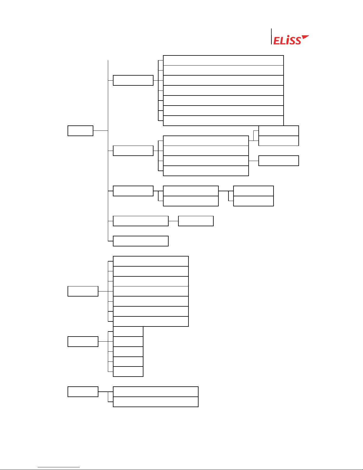
Linux DVR System
Use of DHCP
IP
Network setup Net Mask
Gateway
Port
Number of simultaneous users
Network image quality (Select up to 1~5)
* SETUP N/O
Setup N/C
Sensor
Storage continuous-time setup
Storage Camera setup
Alarm (Select up to ALARM 1~4)
Alarm Setup N/O
Continuous time N/C
Parallel port setup Digital out
System manager
Screen divided into 16
Screen divided into 13
Screen divided into 9
* DIV Screen divided into 8
Screen divided into 6
Screen divided into 4
Full screen
PAN
* PTZ TILT
FOCUS
LIGHT
POWER
LeadTech
13
* BACKUP Back-up with LDV extension
Back-up with AVI extension
Linux DVR System
V . Name and Function of Each Part of ELiSS LD-1600
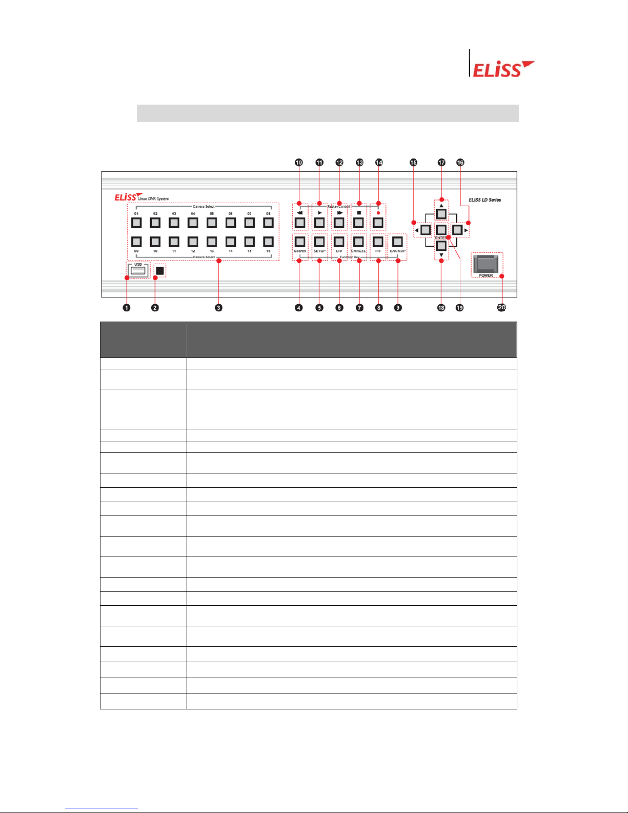
1. Name and Function of Each Part of Front Operating Panel
Name of Operating
Button
Function
① USB Port
- Terminal for USB connection
② 리모콘 센서 - 리모콘 신호를 수신하는 곳 입니다.
③ Camera Select
(01~16)
- When pressing the camera channel button desired among camera channel of 01~16 pieces,
then the concerned screen is shown in full screen.
- Used as number-entering key on password input (The number 10 channel button is
0 on password input)
④ Search
- Converts the screen into SEARCH MODE and DISPLAY MODE
⑤ SETUP
- Converts the screen into SETUP MODE
⑥ DIV
- Change division mode of the screen into 16 division→13 division→9 division→8 division→6
division→4 division→Full screen mode.
⑦ CANCEL
- Used when canceling setup contents.
⑧ PTZ
- Used when entering PAN/TILT Operation MODE.
⑨ BACKUP
- Used when entering BACKUP MODE.
⑩ ◀◀
- If you press this on retrieval of recorded data, reverse direction high-speed search is
executed.
⑪ ▶
- If you press this once, recorded data is regenerated. Pressing once more stops the screen
being regenerated temporarily.
⑫ ▶▶
- If you press this on regeneration of recorded data, right direction high-speed search is
executed. In case of during temporary stop. Move forward by one frame.
⑬ ■
- Converts MODE into DISPLAY MODE.
⑭ ●REC
- Executes total storage in DISPLAY MODE regardless of schedule.
⑮ ◀
- Moves the location of cursor to the left /- Search is made moving backward by 5 minutes in
Search Mode.
○
16
▶
- Moves the location of cursor to the right /- Search is made moving forward by 5 minutes in
Search Mode.
○
17
▲
- Moves up the location of cursor /- Used as CAMER CHANGE(+) button
○
18
▼
- Moves down the location of cursor /- Used as CAMER CHANGE(-) button
○
18
ENTER
- Used when selecting and storing value.
○
16
▶
- Turns ON/OFF ELiSS LD-1600.
LeadTech
14
Linux DVR System
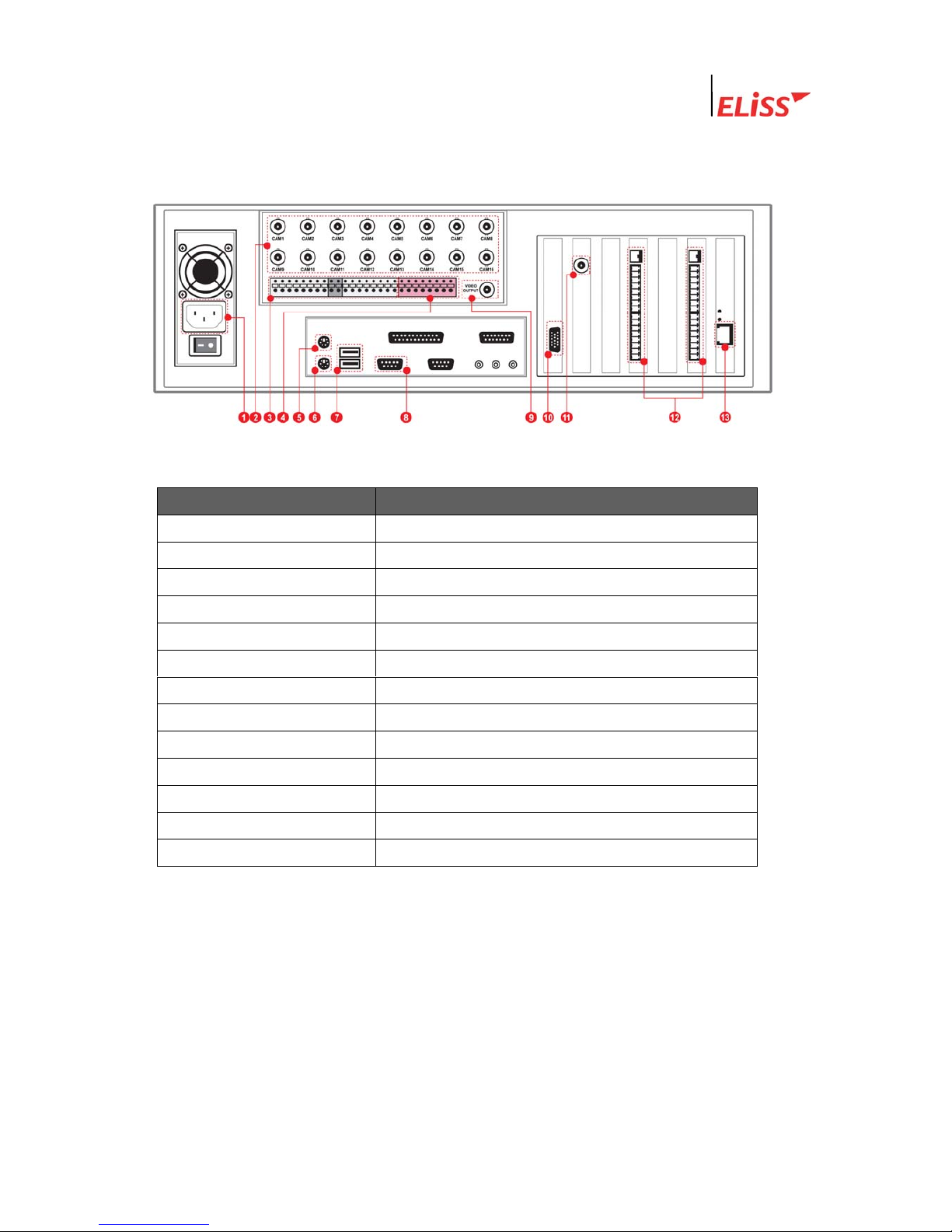
2. Name and Function of Each Part of Rear Side Connection Terminal
VI .
Name of Connection Terminal Function
① Power
AC 100V ~ 240V, 50/60Hz
② CAM01~CAM12
Camera input terminal(12ch)
③ SENSOR INPUT
Terminal receiving input of 16 sensors.
④ ALARM OUTPUT
Terminal for the output of 4 alarms.
⑤ MOUSE
Terminal for the connection of mouse.
⑥ keyboard
Terminal for the connection of keyboard.
⑦ COM1
COM1 Port for the control of PTZ.
⑧ USB port
Terminal for the connection of USB.
⑨ TV OUT 1
TV OUT terminal (CAPTURE)
⑩ VGA
Terminal for the connection of VGA monitor.
⑪ TV OUT 2
TV OUT terminal (OVERLAY)
⑫ SENSOR ALARM Terminal
Terminal for connecting SENSOR, ALARM
⑬ Ethernet
Terminal for the connection of 10/100 network
LeadTech
15

Linux DVR System
VII . Method of Installing ELiSS LD-1600
1. Composition Drawing of Entire Rear Side
LeadTech
16

Linux DVR System
VIII . Method of Use of ELiSS LD-1600
1. Power ON/OFF of ELiSS LD-1600
Power of DVR must be turned ON after all installation of ELiSS LD-1600 is completed.
Check the voltage of input power before turning ON power switch. Using after converting
power conversion switch on the rear side of ELiSS to the matching voltage.
1) Press power switch of ELiSS LD-
1600 long for approximately 4
seconds.
2) Initial Screen
- When power switch of ELiSS LD-
1600 turned ON, following logo
picture is displayed showing the
product.
3) Enter to the Display Mode (Monitor
mode) screen divided into 16.
LeadTech
17
Linux DVR System
2. DISPLAY MODE(Monitor Mode)
DISPLAY MODE(Monitor Mode) performs the function of showing the image in real time
and moving image relayed through installed camera. When power of ELiSS LD-1600 turns
ON, the user enters into Display Mode Screen.
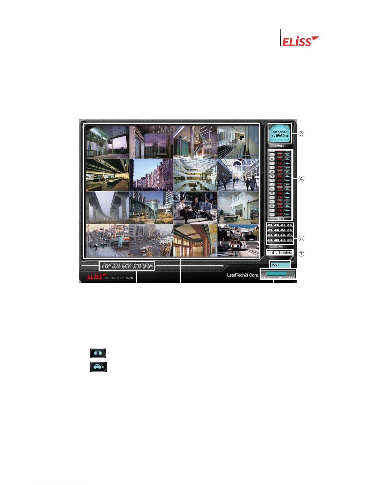
2.1. Explanation of DISPLAY MODE Screen
② ① ⑧
③
④
⑤
⑦
① As a DISPLAY sphere, present picture is the screen divided into 16.
( Refer to p. Change of screen division.)
② Indicates present MODE. Present MODE is DISPLAY MODE.
③ Indicates present date and time.
④ Indicates storage status of each of 16 cameras by Icon.
Icon that indicates concerned camera is storing all.
Icon that indicates concerned camera is storin
g
motion.
⑤ The operating sensors among 16 sensors shine with yellow light.
⑥ The operating alarms among 4 alarms shine with red light.
⑦ Client (EyeLinker Program) 에서 접속중인 user 수를 표시합니다.
⑧ 현재 ELiSS의 총 저장용량과 사용중인 용량을 표시합니다.
LeadTech
18
Linux DVR System
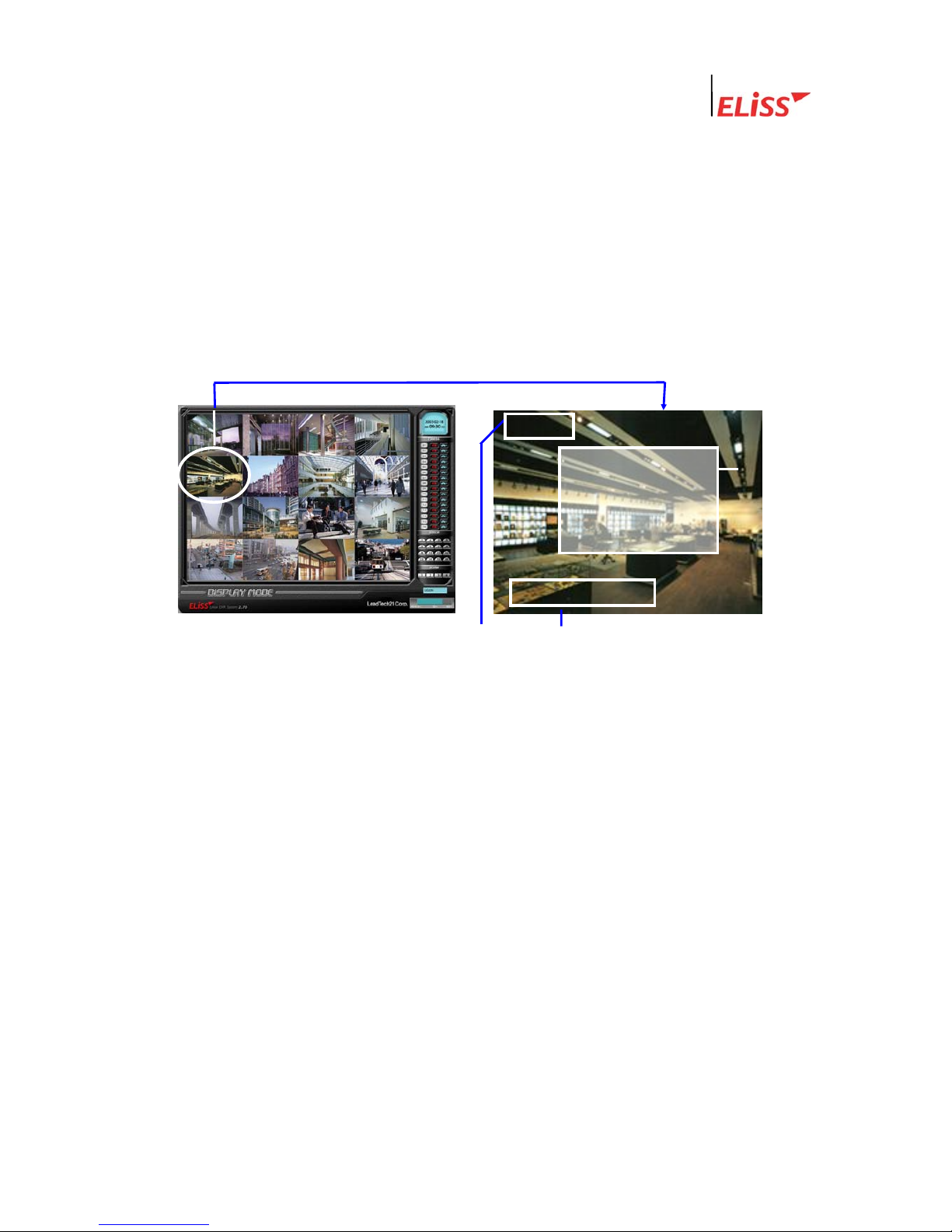
2.2. Explanation of Contents Displayed on Each Screen (The case when OSD
setting is ON)
SETUP-In general setup, when you change OSD setup to ON, setup value by each camera
channel is displayed on the screen. The contents displayed on the screen are as follows.
SETUP-When you change OSD setup to OFF in general setup, the following contents are
not displayed on the screen.
( Refer to p.4.5 OSD setup)
<DISPLAY MODE of Screen divided into 16> <Contents displayed on each screen>
<Expansion>
③
CAM ID
①
②
R M P S
① Camera ID : Camera ID that image is flashed is marked at upper left side of concerned
screen. ID of each individual camera can be set up at the discretion of user at SETUP
MODE.
(Refer to p: 5.3. Camera ID Change)
② Storage status and setup status by each camera channel are shown in alphabet initials.
R : Initial indicating that concerned camera is executing entire storage.
M : Initial indicating that concerned camera is executing motion storage.
S : Initial indicating that the sensor is in operation.
P : Initial indicating that concerned camera is set up with pan/tilt camera.
( Refer to PTZ type/ID setup in p.66: 5.6.)
What is PAN/TILT Camera?※
Pan/TILT is a rotator that rotates the camera up/down and left/right, and it is a device
for the expansion of monitor scope. It is a device to eliminate the area that camera
image can not catch (dead angle area). The camera equipped with such PAN/TILT is
named as Pan/Tilt Camera.
LeadTech
19
Linux DVR System
③ Indication of Motion Sphere : When moving is sensed in the set area while in setup as
motion storage, sensed area is changed to blue color.
(Refer to Motion setup on p.68:
5.8..)
In camera setup, if Display of Motion Setup is set to OFF, no sphere indication is shown ※
on the screen.
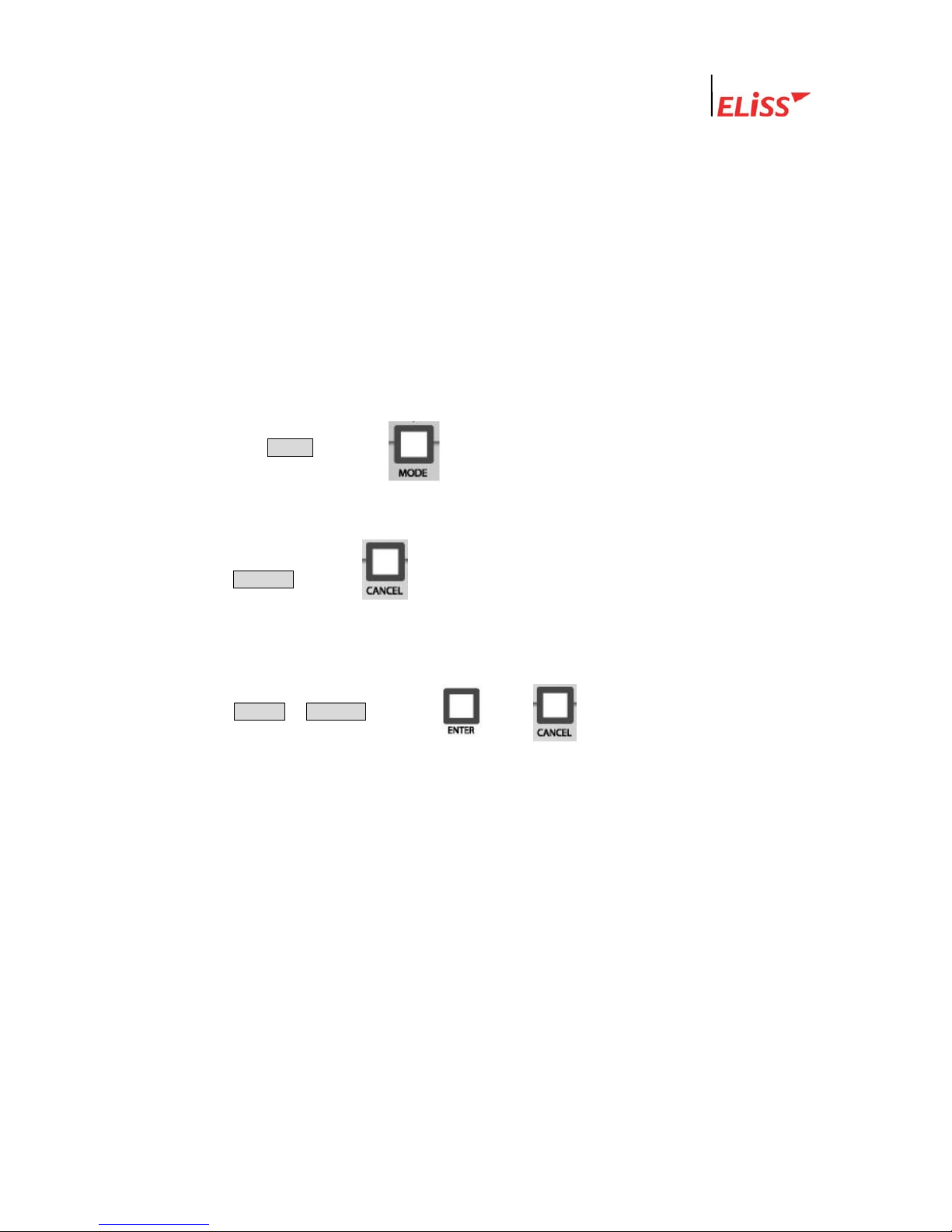
2.3. Conversion to Display Mode from Other Mode
2.3.1. Conversion to Display Mode from Search Mode
If you press MODE button ( ) from Search Mode, conversion to DISPLAY MODE
로 is made.
2.3.2. Conversion to Display Mode from Setup Mode
When CANCEL button ( ) is pressed from initial menu screen of Setup Mode,
conversion to Display Mode is made.
2.3.3. Conversion to Display Mode from PTZ MODE
When ENTER / CANCEL button( / ) is pressed from PTZ Mode,
conversion to Display Mode is made..
LeadTech
20
Linux DVR System
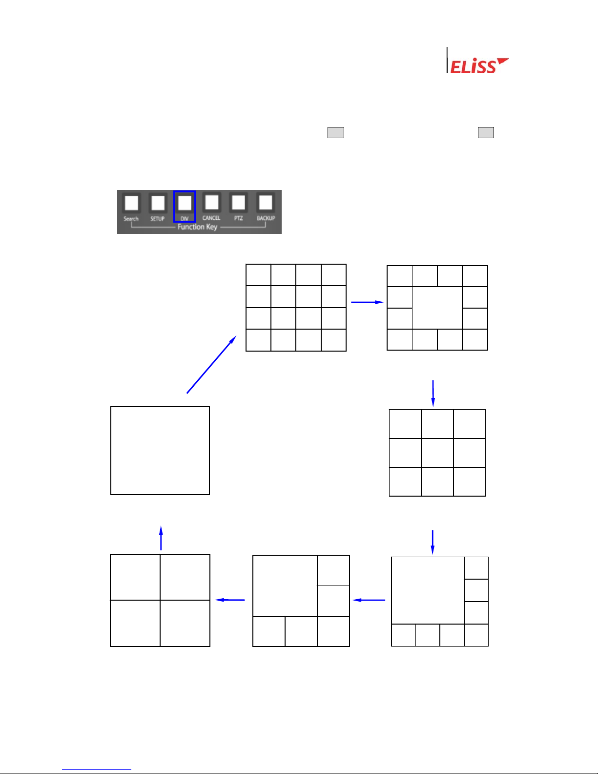
2.4. Change of Screen Dividing from Display Mode
You can change screen dividing mode by using DIV button. Each one pressing of DIV
button converts the screen in the order of 16-division screen → 13-division screen → 9-
division screen → 8-division screen → 6-division screen→ 4-division screen→ Full screen →
16-division screen → 13-division screen.…….
CAM1 2 3
4 5 6
7 8 9
CAM1
<16 division screen >
<13 division screen >
10 11 12 13
CAM1 2 3 4
5 6 7
8 9
CAM1 2 3 4
5 6 7 8
9 10 11 12
13 14 15 16
CAM1 2
3 4
5 6 7 8
CAM1 2
3
4 5 6
CAM1 2
3 4
< 9 division screen >
< 8 division screen >
< 6 division screen >
<4 division screen >
< Full screen >
LeadTech
21
Linux DVR System
2.5. Automatic Channel Switching Function and TV OUT
Automatic Channel Switching Function is the function that automatically change
camera channel shown on the screen in case of screen divided into 13, screen divided into 9,
screen divided into 8, screen divided into 6, screen divided into 4 and Full screen. When
channel switching time interval is set up, camera channel on the screen automatically
changes at the set time interval. Time interval of channel switching can be set at the
discretion of user in setup mode.
(Refer to Channel Switching Setup and TV OUT on p.56: 4.4.)
When common analog TV is connected to TV OUT terminal at connection terminal in the
rear side of ELiSS LD-1600, same TV screen as the screen of ELiSS LD-1600 is output.
Setup of channel switching is equally applied to TV OUT screen.
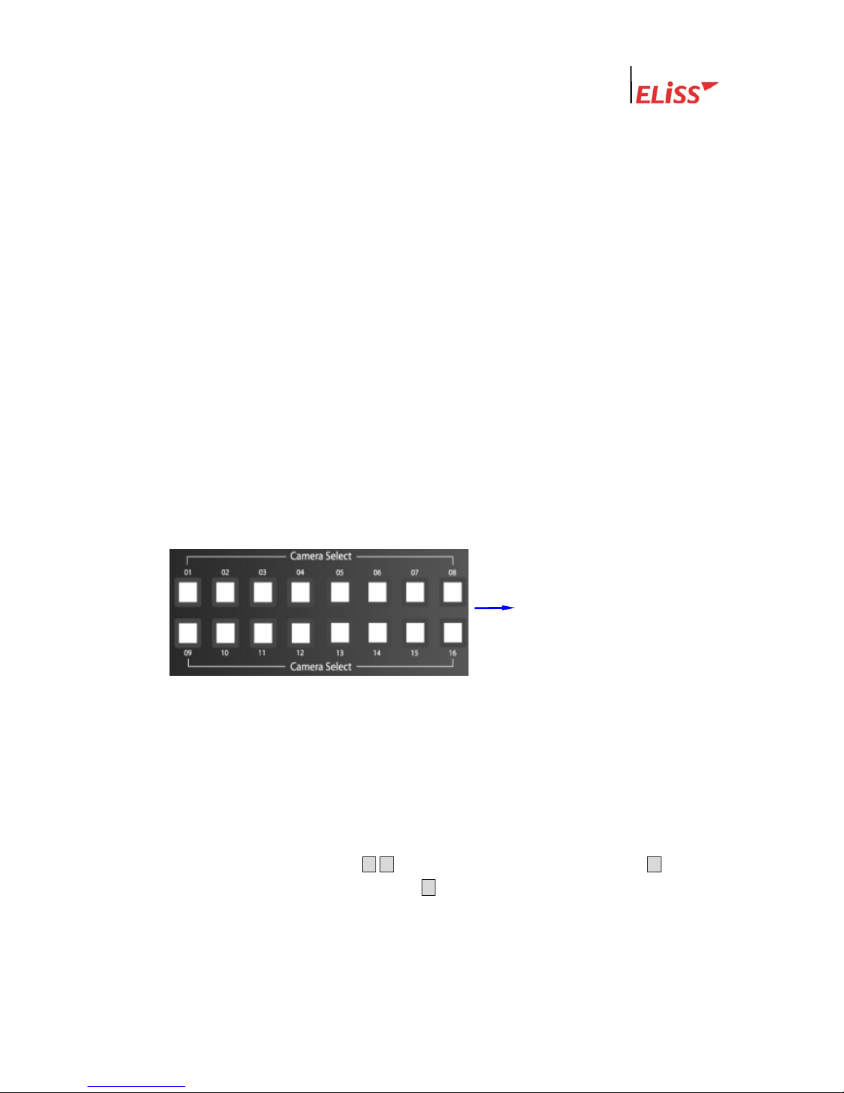
2.6. Conversion of Camera Channel from DISPLAY MODE Screen
When a user presses any desired channel button in DISPLAY MODE by using 16 Camera
Select buttons located on the front side of EliSS LD-1600, such camera channel is directly
converted into Full screen so that the user may monitor the screen.
If you enter password, Camera Select button may be used as number-entering button. At the
time of password input, number 10 channel button is recognized as ‘0’.
If you press the desired camera
channel, the relevant camera
screen is converted into Full
screen mode so that you may
see.
2.7. Conversion of camera channel from DISPLAY MODE screen
This is a function to see the channel presently not shown in screen divided into 9/screen
divided into 8/screen divided into 4/Full screen mode. To convert camera channel shown on
the screen in EliSS LD-1600, use ▲/▼ button among Direction Movement buttons. ▲ button
increases (+) channel of the camera and ▼button decrease (-) channel of the camera.
Conversion of camera channel is impossible in case of screen divided into 13 and screen
divided into 6.
LeadTech
22
Linux DVR System
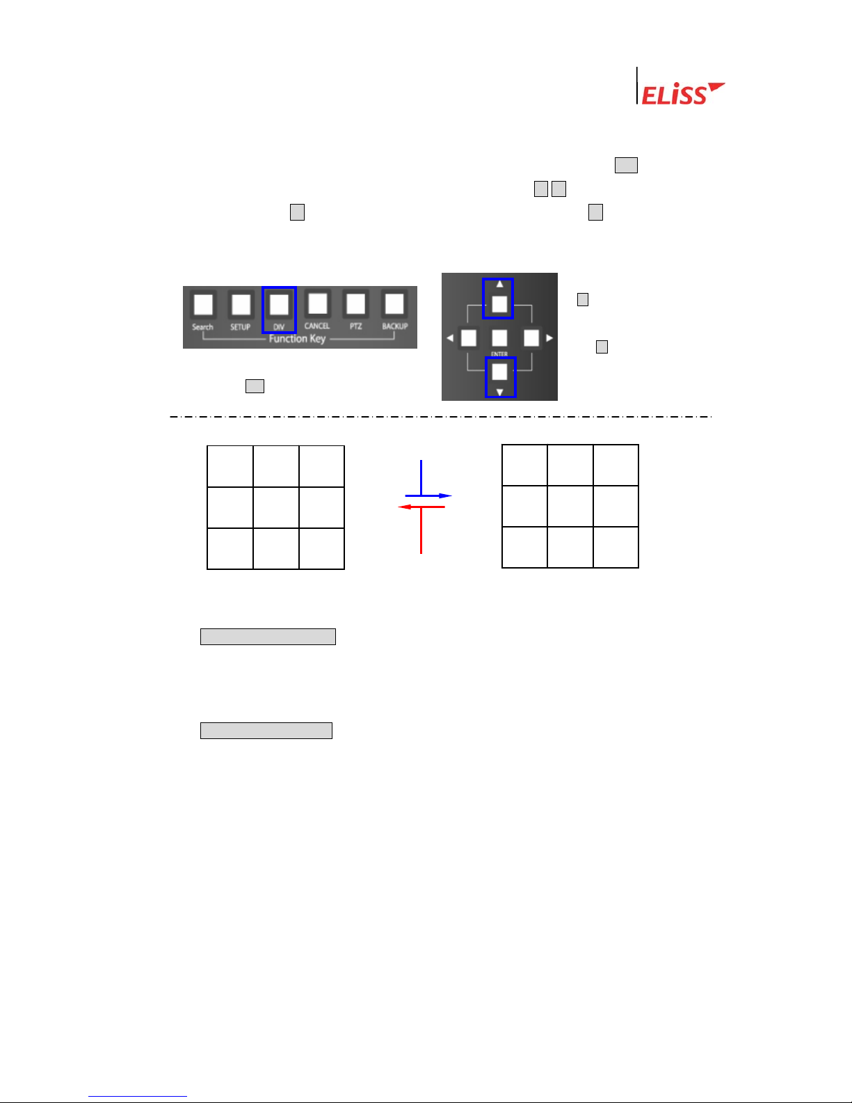
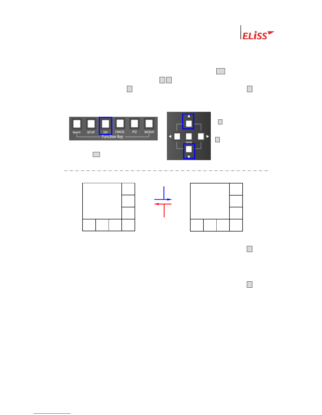
2.7.1. Conversion of Camera Channel from Screen Divided into 9
Firstly, set the division of the screen to the screen divided into 9 using DIV button. To
convert camera channel which is shown on the screen, use ▲/▼button among Direction
Movement buttons. ▲ button increases (+) channel of the camera and ▼ button decreases
(-) channel of the camera.
This is the direction in which camera channel is converted by every 1 pressing of ①
CAMERA CHANGE(+) button among Direction Movement buttons from the screen
divided into 9. (Converted in the order of CAM1~CAM9 screen→ CAM8~CAM16
screen→ CAM1~CAM9 screen→ CAM8~CAM16 screen→ …….)
This is the direction in which camera channel is converted by every 1 pressing of ②
CAMERA CHANGE(-) button among Direction Movement buttons from the screen
divided into 9. (Converted in the order of CAM1~CAM9 screen→ CAM8~CAM16
screen→ CAM1~CAM9 screen→ CAM8~CAM16 screen → …….)
1) Convert to screen divided into 9 by
pressing DIV button.
2) ▲button increases (+)
channel of the camera
and ▼button decreases
(-) channel of the camera.
CAM8 9 10
11 12 13
14 15 16
7 8 9
4 5 6
CAM1 2 3
②
①
LeadTech
23
Linux DVR System
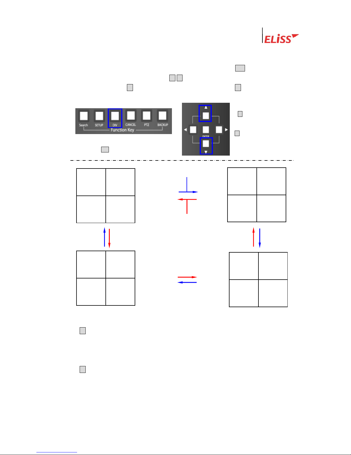
2.7.2. Conversion of Camera Channel from Screen Divided into 8
Firstly, set division of the screen to the screen divided into 8 by using DIV button. To convert
camera channel shown on the screen, use ▲ /▼button among Direction Movement buttons
in case of EliSS LD-1600. ▲button increases (+) channel of the camera and ▼button
decreases (-) channel of the camera. .
1) Convert into the screen divided into 8 by
pressing DIV button.
2) ▲button increases (+)
camera channel and
▼button decreases (-)
camera channel.
①
5 6 7 8
CAM1 2
4
3
CAM9 10
13 14 15 16
12
11
②
This is the direction in which camera channel is converted by every 1 pressing of ① ▲button
among Direction Movement buttons from the screen divided into 8. (Converted as
CAM1~CAM8 screen→CAM9~CAM16 screen→CAM1~CAM8 screen→CAM9~CAM16
screen→ …….)
This is the direction in which camera channel is converted by every 1 pressing of ② ▼button
among Direction Movement buttons from the screen divided into 8. (Converted as
CAM1~CAM8 screen→ CAM1~CAM16 screen→CAM1~CAM8 screen→CAM9~CAM16
screen→ …….)
LeadTech
24
Linux DVR System
2.7.3. Conversion of Camera Channel from Screen Divided into 4
Firstly, set division of the screen to the screen divided into 4 by using DIV button. To convert
camera channel shown on the screen, use ▲/▼button among Direction Movement buttons in
case of ELiSS LD-1600. ▲button increases (+) camera channel and ▼ button decreases (-)
camera channel..
① This is the direction in which camera channel is converted by every 1 pressing of
▲button among Direction Movement buttons from the screen divided into 4. (Converted
in the order of CAM1~CAM4 screen → CAM5~CAM8 screen → CAM9~CAM 12 →
CAM13~CAM 16 screen →…….)
② This is the direction in which camera channel is converted by every 1 pressing of
▼button among Direction Movement buttons from the screen divided into 4. (Converted
in the order of CAM1~CAM4 screen→ CAM13~CAM16 screen → CAM9~CAM12
screen → CAM5~CAM8 screen →…….)
1) Convert into screen divided into 4 by
pressing DIV button.
2) ▲button increases (+)
camera channel and
▼button decreases (-)
camera channel.
11 12
CAM9 10
3 4
CAM1 2
①
②
15 16
CAM13 14
15 16
CAM13 14
LeadTech
25
Linux DVR System
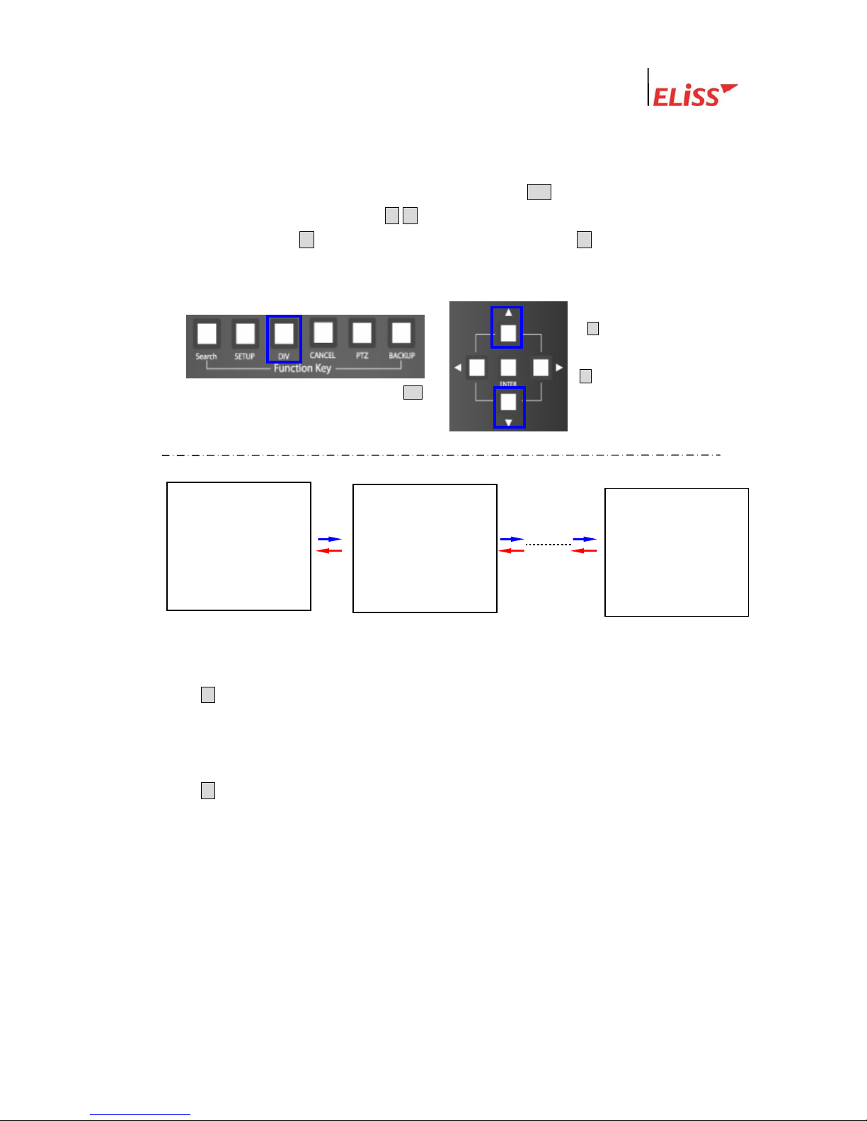
2.7.4. Conversion of Camera Channel from Full Screen
Firstly, set division of the screen to Full screen by using DIV button. To change camera
channel shown on the screen, use ▲/▼ button among Direction Movement buttons in case
of ELiSS LD-1600. ▲ button increases (+) camera channel and ▼ button decreases (-)
camera channel.
1) Convert into Full screen by pressing DIV
2) ▲button increases (+)
camera channel and
▼button decreases (-)
camera channel.
CAM1
CAM2
CAM16
①
②
① This is the direction in which camera channel is converted by every 1 pressing of
▲button among Direction Movement buttons from Full screen . (Converted in the order
of CAM1 Full screen→ CAM2 Full screen→ CAM3 Full screen→…… →CAM15 Full
screen→ CAM16 Full screen→ CAM1 Full screen→…….)
② This is the direction in which camera channel is converted by every 1 pressing of
▼button among Direction Movement buttons from Full screen. (Converted in the order
of CAM1 Full screen→ CAM16 Full screen→ CAM15 Full screen→…… → CAM3 Full
screen → CAM2 Full screen → CAM1 Full screen→……)
LeadTech
26
Linux DVR System
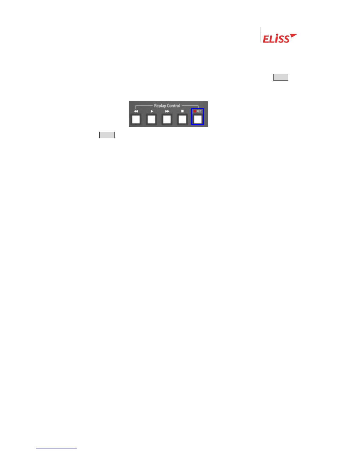
2.8. Real Time Storage in DISPLAY MODE
In ELiSS LD-1600, you can make real time storage in monitor mode. To do that, use ●REC
button located on the front side of ELiSS LD-1600 in DISPLAY MODE screen.
If you press ●REC button in Monitor Mode, it stores all the video displayed on the screen
real time. Even if set up in schedule, it executes all the video. The stored date can be
regenerated in the method of general search in Search Mode.
LeadTech
27
Linux DVR System
3. SEARCH MODE(RETRIEVAL MODE)
Search Mode is a mode that can search/regenerate recorded image by date, by time. It is
converted to Search Mode when pressing MODE button of front side of ELiSS from Display
Mode. Search method has General Search and Event Search.
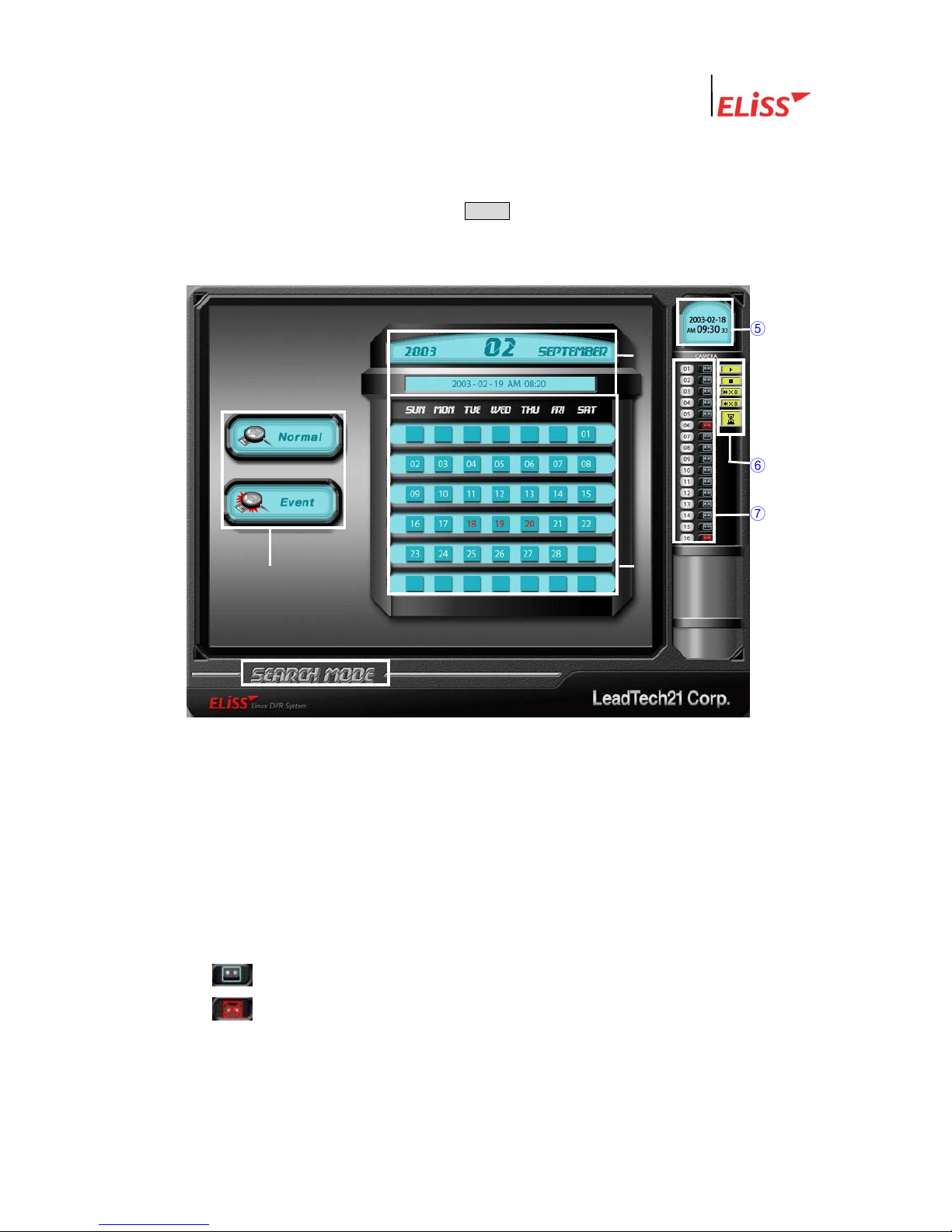
3.1. Explanation of Search Mode (RETRIEVAL MODE) Screen
④
③
②
⑤
⑥
⑦
① Indicates Present Mode. Present Mode is Search Mode.
② Indicates date and time to search, and the user can personally select the date and time
to search.
③ Calendar of the month to search. The date marked in red color is the date that has
recorded data and the date marked in white color is the date without recorded data.
④ The user can search selecting one between general search and event search.
⑤ Indicates present date and time.
⑥ Indicates existing or none of recorded data with icon by each camera channel at
selected time/date.
Indicates existing of recorded data in concerned channel at selected time/date
Icon indicates no recorded data in concerned channel at selected time/date.
⑦ Indicates with icon the status that recorded data is being retrieved presently.
LeadTech
28
Linux DVR System
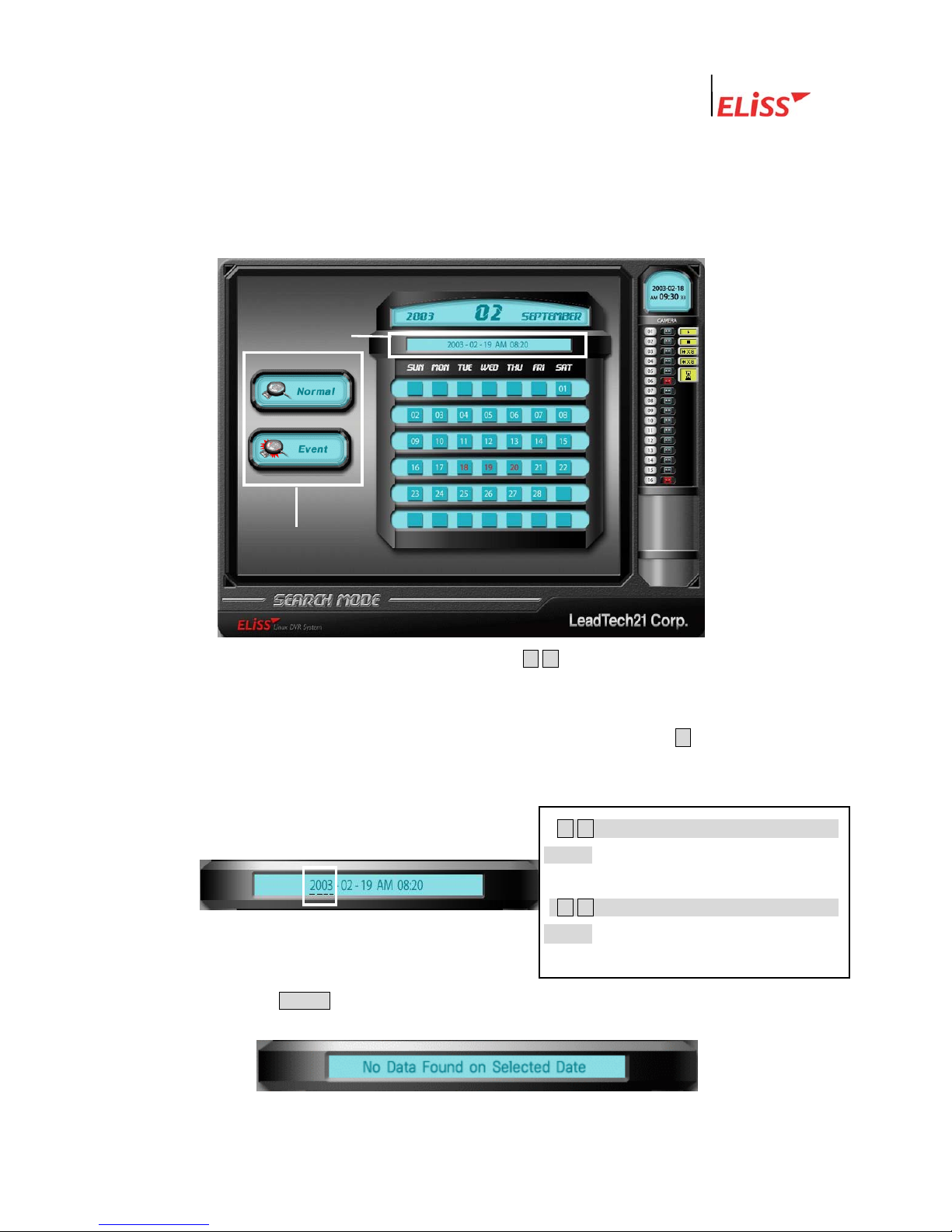
3.2. General Search
General Search is a function that allows the user to select the time/date desired and
search/regenerate entire stored data at such selected time.
3.2.1. Method of General Search
① Place cursor at general search button using ▲/▼ button among Direction Movement
buttons located in the front side of ELiSS. When cursor is placed, general search
button is lit with red light from blue light.
② When the general search button shines with red light, press again ▶ button among
Direction Movement buttons located in the front side of ELiSS. Then the location of
cursor moves to date selection window. Initial cursor is located at the Year.
• ◀/▶ button among Direction Movement
buttons : Moves the location of the cursor
right and left.
• ▲/▼ button among Direction Movement
buttons Changes the figures of the place
where the cursor is located
②
①
③ Press ENTER button when date/time selection is completed. If there is no stored
data on selected time/date, following message is shown..
LeadTech
29
Linux DVR System
3.2.2. Regeneration of Generally Searched Data
After selecting intended time/date, press ENTER button. Then conversion is made to the
screen that regeneration of actual data can be done.
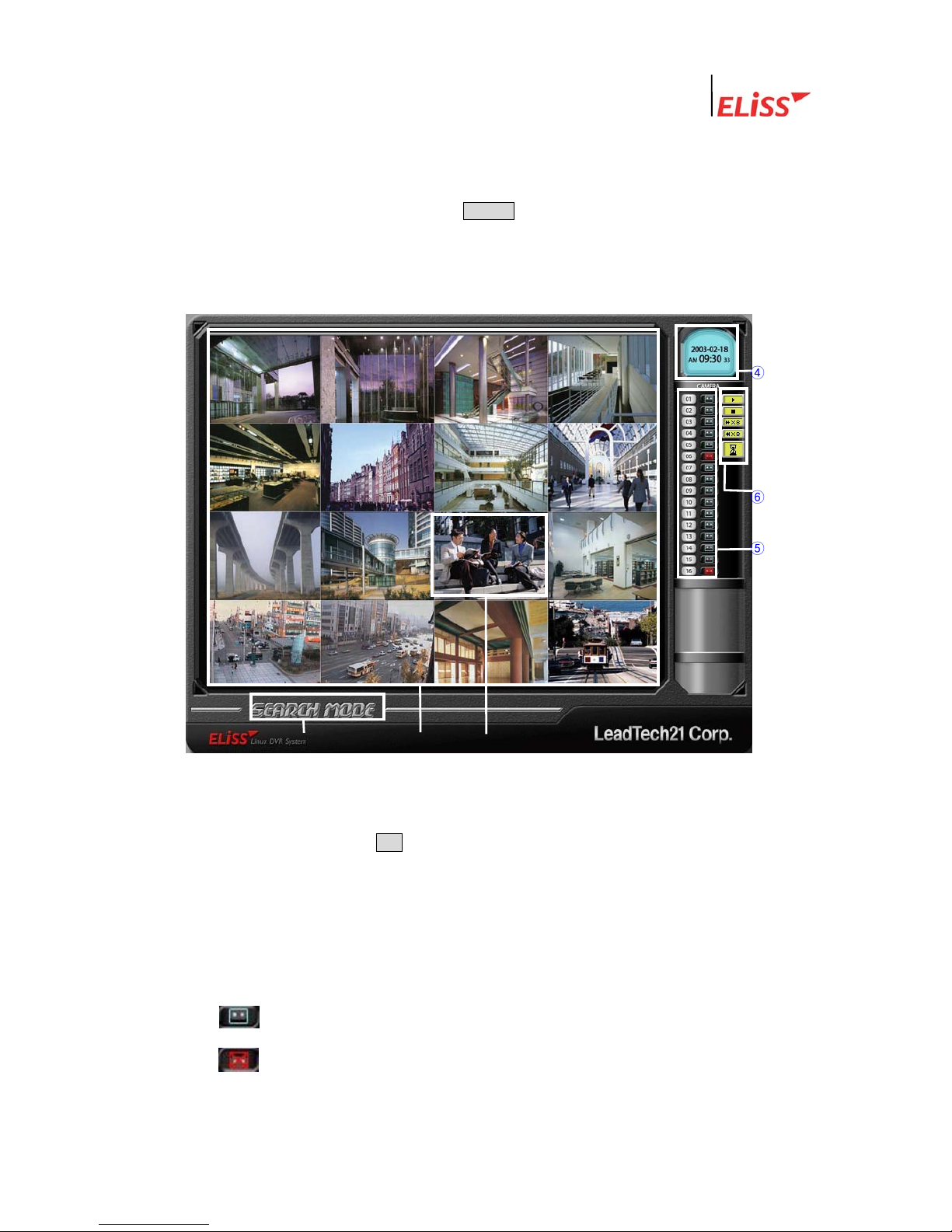
3.2.3. Explanation of Data Regeneration Screen
④
⑥
⑤
① ② ③
① Indicates present mode. Present mode is SEARCH MODE.
② Sphere where recorded data of searched time/date is regenerated. To change the
division of screen, press DIV button located at front side of ELiSS. Division of screen is
changed by each 1 pressing.
③ ‘NO DATA’ message is shown in case of the camera channel with no recorded data at
searched time/date.
④ Time/date when the Image of the screen was taken is displayed.
⑤ Existence or none of recorded data by each camera channel is displayed as icon.
This icon means that concerned channel has recorded data at selected
time/date.
LeadTech
30
This icon means that concerned channel has no recorded data at
selected time/date.
 Loading...