

Elis FLONET FN20xx.1 Series Design, Assembly And Service Manual
ELIS PLZEŇ a. s.
Design, Assembly and Service Manual
Page 1 of 69
Electromagnetic flowmeter FLONET FN20xx.1
ELIS PLZEŇ a. s., Luční 425/15, 30100 Plzeň, Czech Republic, Phone: +420/377 517 711, Fax: +420/377 517 722 Es90420K/c
Electromagnetic Flowmeter
FLONET FN20xx.1

ELIS PLZEŇ a. s.
Design, Assembly and Service Manual
Page 2 of 69
Electromagnetic flowmeter FLONET FN20xx.1
ELIS PLZEŇ a. s., Luční 425/15, 30100 Plzeň, Czech Republic, Phone: +420/377 517 711, Fax: +420/377 517 722 Es90420K/c

ELIS PLZEŇ a. s.
Design, Assembly and Service Manual
Page 3 of 69
Electromagnetic flowmeter FLONET FN20xx.1
ELIS PLZEŇ a. s., Luční 425/15, 30100 Plzeň, Czech Republic, Phone: +420/377 517 711, Fax: +420/377 517 722 Es90420K/c
Content
1. INTRODUCTION ............................................................................................................................................5
2. MEASUREMENT PRINCIPLE .......................................................................................................................5
3. TECHNICAL DESCRIPTION.........................................................................................................................6
3.1. GENERAL DESCRIPTION ............................................................................................................................................... 6
3.2. METER DESIGN........................................................................................................................................................... 6
3.2.1. Remote version................................................................................................................................................ 6
3.2.2. Compact version .............................................................................................................................................. 7
3.2.3. Protection of the flow meters against unauthorised intervention ...................................................................... 8
4. TECHNICAL PARAMETERS.........................................................................................................................9
4.1. FLOW SENSOR............................................................................................................................................................ 9
4.1.1. Selection of correct sensor size........................................................................................................................ 9
4.1.2. Operating pressure of measured liquid .......................................................................................................... 11
4.1.3. Selection of electrode material....................................................................................................................... 12
4.1.4. Selection of sensor tube lining ....................................................................................................................... 12
4.1.5. Compact and remote version ......................................................................................................................... 12
4.1.6. Dimensions of flanged sensor........................................................................................................................ 13
4.1.8. Sensor specifications ..................................................................................................................................... 16
4.2. TRANSMITTER HOUSING............................................................................................................................................. 17
4.2.1. Transmitter specifications............................................................................................................................... 17
5. METER APPLICATION RULES ................................................................................................................. 18
5.1. SENSOR PLACEMENT IN PIPING ................................................................................................................................... 18
5.2. SENSOR GROUNDING ................................................................................................................................................ 20
6. FLOWMETER INSTALLATION AND COMMISSIONING.......................................................................... 21
6.1. SENSOR INSTALLATION.............................................................................................................................................. 21
6.2. ELECTRIC CONNECTION OF FLOWMETER...................................................................................................................... 22
6.2.1. Connection to power supply........................................................................................................................... 22
6.2.2. Output signal connections.............................................................................................................................. 22
6.3. INTERCONNECTION OF SENSOR AND TRANSMITTER (REMOTE VERSION)........................................................................... 23
6.4. INTERCONNECTION OF SENSOR AND TRANSMITTER (REMOTE VERSION WITH IP 68).......................................................... 23
6.5. COMMISSIONING....................................................................................................................................................... 23
6.5.1. The ECONOMIC version................................................................................................................................ 23
6.5.2. The COMFORT version ................................................................................................................................. 23
6.5.3. Operating data ............................................................................................................................................... 24
6.5.3.1. Display formats of aggregate values....................................................................................................... 26
6.5.3.2. Data reset ............................................................................................................................................... 26
7. CONFIGURATION ...................................................................................................................................... 27
7.1. BASIC MENU CONFIGURATION..................................................................................................................................... 28
7.1.1. Displayed data ............................................................................................................................................... 28
7.1.2. Number of samples........................................................................................................................................ 29
7.1.3. Analog output................................................................................................................................................. 30
7.1.4. Output functions............................................................................................................................................. 33
7.1.5. Electrode cleaning.......................................................................................................................................... 39
7.1.6. Serial line ....................................................................................................................................................... 40
7.1.7. Production data.............................................................................................................................................. 42
7.1.8. Dose setting ................................................................................................................................................... 44
7.1.9. Zero setting .................................................................................................................................................... 44
7.1.10. 100 per cent ................................................................................................................................................. 45
7.1.11. Exit............................................................................................................................................................... 45
7.2. THE PARAMETER SETTING MENU................................................................................................................................ 47
7.3. THE PRODUCTION DATA MENU ................................................................................................................................... 48
8. ERROR REMOVAL AND METER REPAIR PROCEDURES..................................................................... 49
8.1. REPLACEMENT PC BOARDS .............................................................................................................................. 49
8.2. PROGRAM AND SIMULATION SOFTWARE ........................................................................................................ 49
8.3. FLOWMETERREPAIR PROCEDURE .................................................................................................................. 49
8.3.1. KV 1.0 Fixture for checking the meter outputs ............................................................................................... 53

ELIS PLZEŇ a. s.
Design, Assembly and Service Manual
Page 4 of 69
Electromagnetic flowmeter FLONET FN20xx.1
ELIS PLZEŇ a. s., Luční 425/15, 30100 Plzeň, Czech Republic, Phone: +420/377 517 711, Fax: +420/377 517 722 Es90420K/c
8.3.2. Checking the sensor condition (compact version).......................................................................................... 54
8.3.2.1. Measurements to be performed on sensor with no liquid inside (the lining is dry).................................. 54
8.3.2.2. Checking the sensor condition fitted into piping and flooded with a measured liquid.............................. 55
8.3.3. Checking the sensor condition (remote transmitter with IP67 housing).......................................................... 56
8.3.3.1. Measurements to be performed on sensor with no liquid inside (the lining is dry) .................................. 56
8.3.3.2. Checking the sensor condition fitted into piping and flooded with a measured liquid.............................. 57
8.3.3.3. Checking the condition of the cable connecting sensor and associated transmitter ............................... 57
8.3.4. Checking the sensor condition (remote transmitter with IP68 housing).......................................................... 58
8.3.4.1. Checking the sensor condition fitted into piping and flooded with a measured liquid.............................. 59
8.3.5. Checking the flowmeter condition with a diagnostic module of FLOSET 2.0 program ................................... 59
9. SERVICE ACTIVITIES ................................................................................................................................ 60
9.1.WARRANTY SERVICE ................................................................................................................................................. 60
9.2. POST-WARRANTY SERVICE......................................................................................................................................... 60
10. STANDARD TESTS.................................................................................................................................. 60
11. CALIBRATION.......................................................................................................................................... 60
12. PRODUCT ORDERING ............................................................................................................................ 61
13. PACKAGING............................................................................................................................................. 68
14. PRODUCT ACCEPTANCE....................................................................................................................... 68
15. WARRANTY CONDITIONS...................................................................................................................... 68
ELIS PLZEŇ a. s.
Design, Assembly and Service Manual
Page 5 of 69
Electromagnetic flowmeter FLONET FN20xx.1
ELIS PLZEŇ a. s., Luční 425/15, 30100 Plzeň, Czech Republic, Phone: +420/377 517 711, Fax: +420/377 517 722 Es90420K/c
1. INTRODUCTION
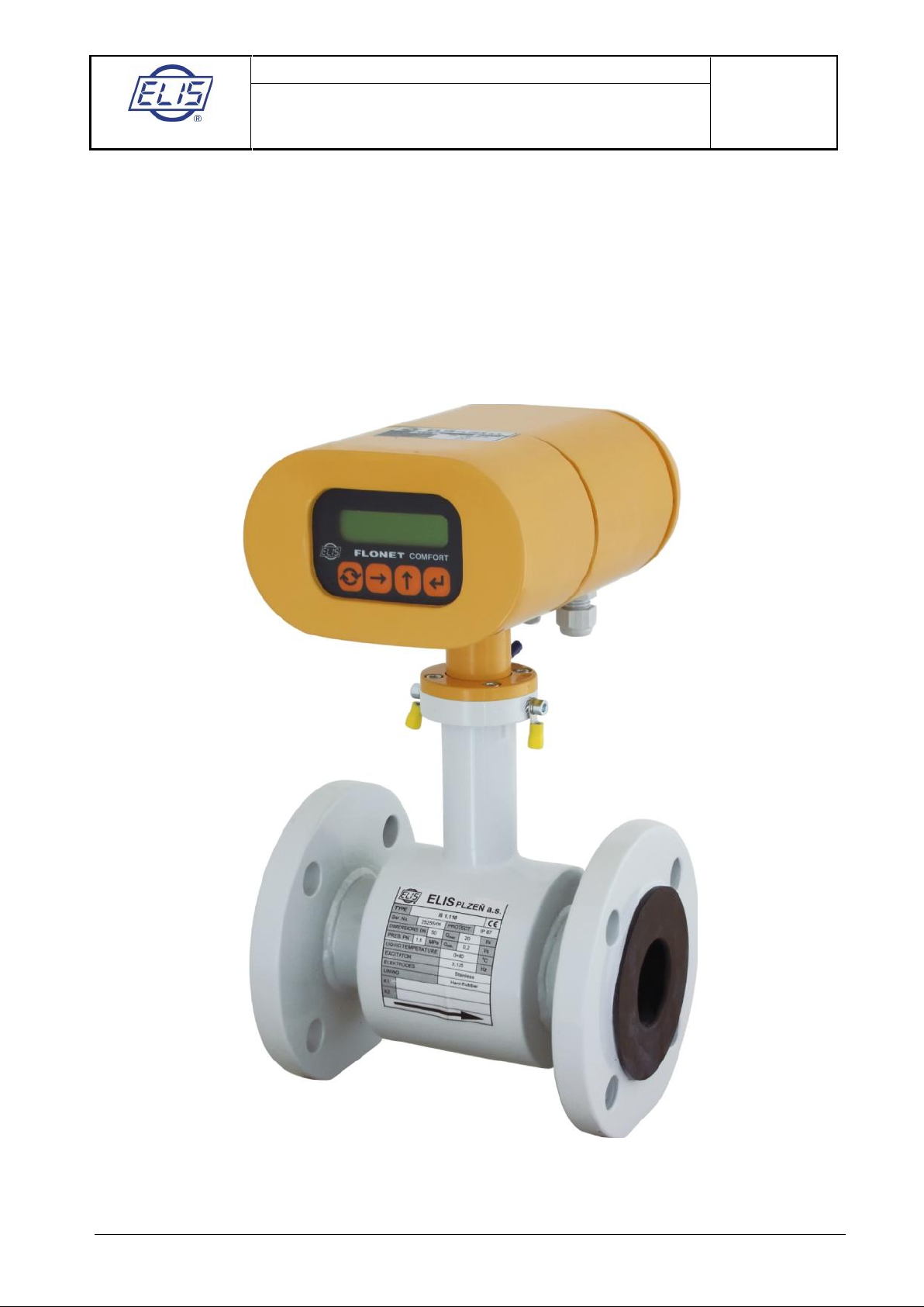
The FLONET FN20xx.1 electromagnetic flowmeter has been designed to measure volume flow rates of
electrically conductive liquids in closed piping systems. The flow measurement can be carried out bidirectionally, with a high measurement accuracy over a wide range of flow rates (0.1 to 10 m/s / 0.33 to 33
ft/s). The minimum required conductivity of the measured medium is 5 µS/cm.
The transmitter includes a two-line alphanumeric display to show the measured values where various
operating parameters of the meter can be selected on a keypad. The flowmeter has two passive binary
outputs, one active current output and an output to connect a digital communication line. All meter functions
and output parameters can be reset during the meter operation. If the meter is to be used as an invoicing
meter, some of its functions are blocked to prevent the user from interfering with the meter readings.
The user may combine any sensor of the IS X.xx type series with any transmitter (C 6.00 or C 7.00) without
re-calibration of the meter on a test stand (however, such calibration is required for invoicing meters). The
only thing that needs to be done is to enter the calibration constants and excitation frequency of the selected
sensor into the transmitter memory. These data are mentioned on the rating plate of the sensor. The value of
threshold flow rate shall be set between 0.5 and 1% of the specified maximum flow rate.
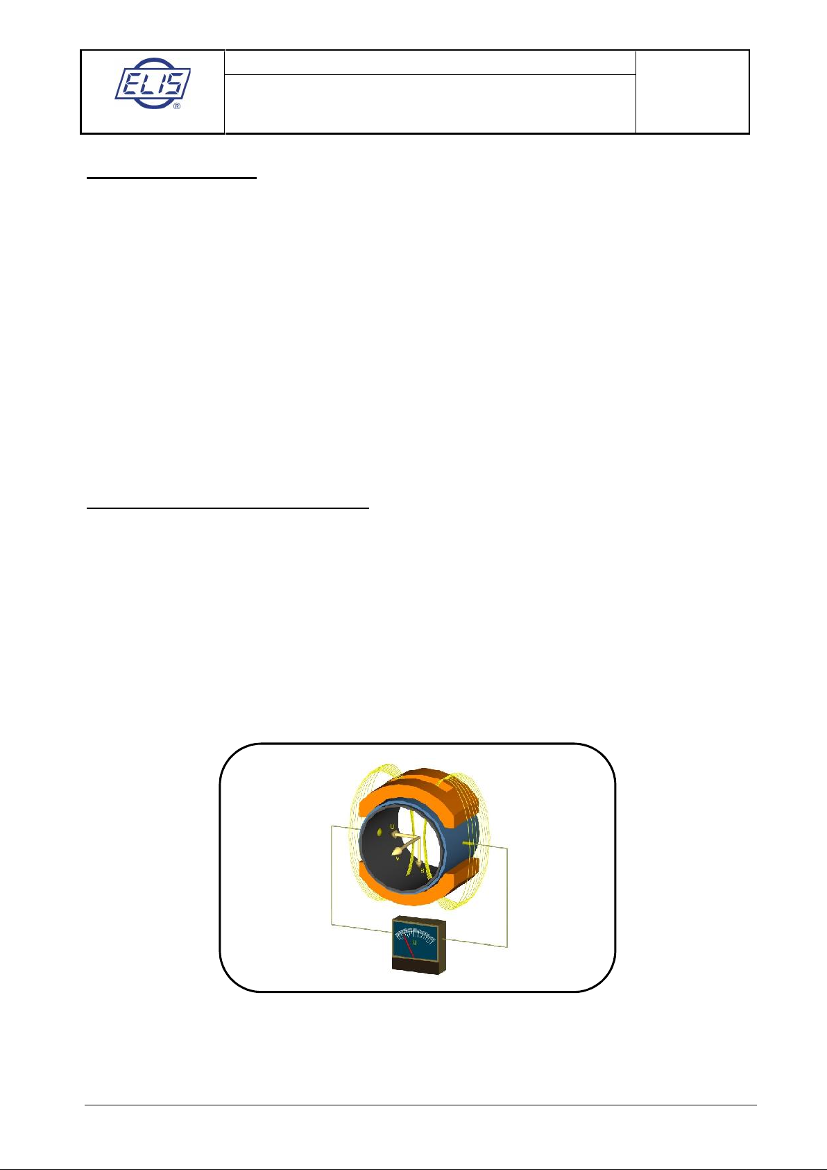
2. MEASUREMENT PRINCIPLE
The function of an electromagnetic flowmeter is based on Faraday's law of induction. The meter sensor
consists of a non-magnetic and non-conductive tube with two embedded measuring electrodes detecting the
induced voltage. The alternating magnetic field is created by two coils fitted onto the tube parallel to the
plane of the measuring electrodes. When a conductive liquid moves in a magnetic field B, voltage U will be
detected on the measuring electrodes. Such a voltage is proportional to the flow velocity v and the conductor
length l.
U = B x l x v
U induced voltage
B magnetic flux density
l distance between measuring electrodes
v liquid flow velocity
As the magnetic flux density and distance between the electrodes are constant, the induced voltage is
proportional to the liquid flow velocity in the tube. The value of the volume flow rate can then be determined
as a product of the flow velocity and square section of the tube, Q = v x S.
ELIS PLZEŇ a. s.
Design, Assembly and Service Manual
Page 6 of 69
Electromagnetic flowmeter FLONET FN20xx.1
ELIS PLZEŇ a. s., Luční 425/15, 30100 Plzeň, Czech Republic, Phone: +420/377 517 711, Fax: +420/377 517 722 Es90420K/c
3. TECHNICAL DESCRIPTION
3.1. General description
The electromagnetic flowmeter consists of a sensor through which flows the measured liquid and an
transmitter where the low-level signal from a sensor is modified to the standardised form suitable for further
processing in various industrial electronic devices. The output signal is proportional to the volume flow rate of
the measured liquid. The only factor limiting the application of induction flow meters is the requirement that
the measured liquid must be conductive and non-magnetic. The induction flow meter can be designed either
as a compact device or with the sensor separated from the associated transmitter. In the former case, the
transmitter is fitted directly onto the meter sensor, in the latter case it is connected to the sensor by a special
cable.
The sensor design shall take into consideration the type of the measured liquid and its operational
parameters. To facilitate fitting into the liquid piping, the sensor can be provided with end flanges, screwing,
or it may be of a sandwich design. The transmitter is supplied in two basic versions, COMFORT or
ECONOMIC. The supply voltage, types of output signal and communication interface can be selected
according to the customer requirements.
The basic configuration of the induction flow meter includes two insulated passive binary outputs (each with
an optocoupler including a transistor output) and the USB communication interface. This interface is not
insulated as it is used for calibration purposes only. Optional accessories to this basic configuration are
insulated current output and insulated RS-485 communication interface, output relay, INPUT1 and
OUTPUT3 for batching (all these electrically insulated from the transmitter circuitry).
3.2. Meter design
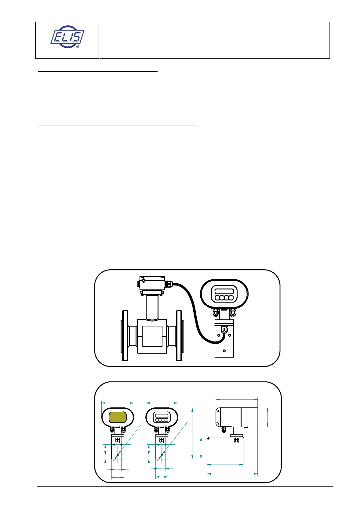
3.2.1. Remote version
Flanged sensor connected by cable to the remote transmitter
Dimensions of the box to accommodate remote transmitter and the mounting bracket
200
92
170
240
110
250
154154
35
60
5020
5020
35
60
O
6,5
3
x
O
6,5
3
x
Economic Comfort

ELIS PLZEŇ a. s.
Design, Assembly and Service Manual
Page 7 of 69
Electromagnetic flowmeter FLONET FN20xx.1
ELIS PLZEŇ a. s., Luční 425/15, 30100 Plzeň, Czech Republic, Phone: +420/377 517 711, Fax: +420/377 517 722 Es90420K/c
3.2.2. Compact version
Compact version with flanged sensor and transmitter
Compact version with flangeless sensor and transmitter
Housing dimensions in the compact version
Economic
Comfort
154
200
92
140
154
Economic
Comfort
154
200
92
140
154
ELIS PLZEŇ a. s.
Design, Assembly and Service Manual
Page 8 of 69
Electromagnetic flowmeter FLONET FN20xx.1
ELIS PLZEŇ a. s., Luční 425/15, 30100 Plzeň, Czech Republic, Phone: +420/377 517 711, Fax: +420/377 517 722 Es90420K/c
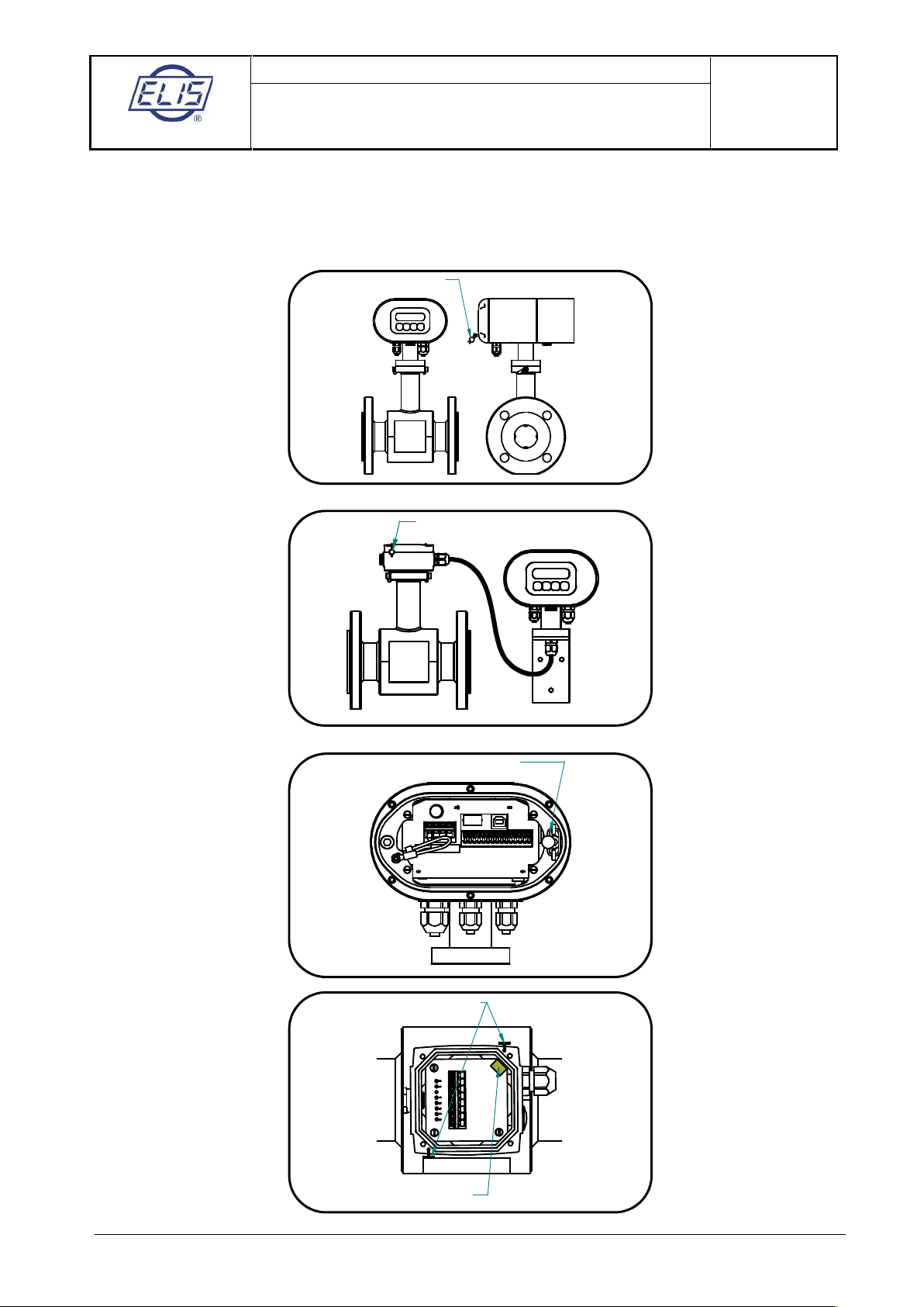
3.2.3. Protection of the flow meters against unauthorised intervention
The flow meter is delivered with official and assembly seals. It is recommended, installation of flow meters is
reserved to duly authorised organisation(s).
Placement of official and assembly seals on meters in compact and remote versions.
Assembly seal
Assembly seal
Official seal
Assembly seal
Official seal
ELIS PLZEŇ a. s.
Design, Assembly and Service Manual
Page 9 of 69
Electromagnetic flowmeter FLONET FN20xx.1
ELIS PLZEŇ a. s., Luční 425/15, 30100 Plzeň, Czech Republic, Phone: +420/377 517 711, Fax: +420/377 517 722 Es90420K/c
4. TECHNICAL PARAMETERS
4.1. Flow sensor
The sensor environment must be free of any strong magnetic fields.
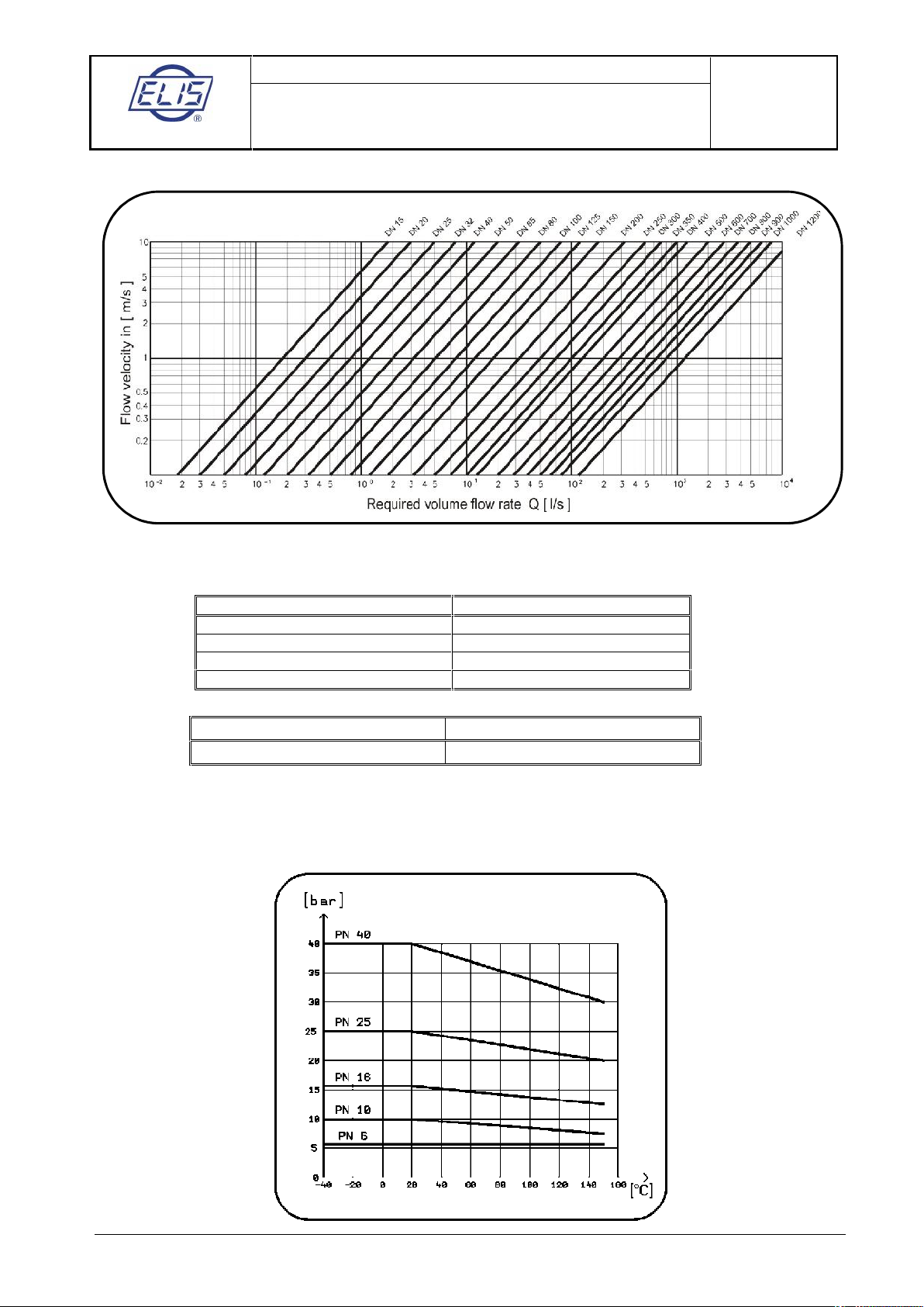
4.1.1. Selection of correct sensor size
The following table shows minimum and maximum flow rates for various sensor sizes and flow velocities
ranging from 0.1 to 10 m/s (0.33 to 33 ft/s). The best operational properties will be achieved at the flow
velocity range of 0.5 to 5 m/s (1.64 to 16.4 ft/s). For lower flow velocities, the measurement accuracy is lower
while at higher flow velocities the turbulences at contact edges may cause undesirable interference.
Minimum and maximum flow rates for various sensor sizes
Q1corresponds to flow velocity 0.1 m/s (0.33 ft/s)
Q4corresponds to flow velocity 10.0 m/s (33 ft/s)
Basic parameters of the flow meters are designed according to standard EN ISO 4064-1 (OIML R 49).
The ratio of following flows is shown below:
Q
4
= 1.25
Q
2
= 1.6
Q3Q
1
Flow meter precision rating in accordance with standard EN ISO 4064-1 (OIML R 49)
The figures in the table are based on standard EN ISO 4064-1 (OIML R 49).
The flow rate values Q1, Q2, Q3and Q4related to individual design versions and meter dimensions are
shown below in the Table 1:
-6
-4
-2
0
2
4
6
Q1 Q2 Q3 Q4
Relative error [%]

ELIS PLZEŇ a. s.
Design, Assembly and Service Manual
Page 10 of 69
Electromagnetic flowmeter FLONET FN20xx.1
ELIS PLZEŇ a. s., Luční 425/15, 30100 Plzeň, Czech Republic, Phone: +420/377 517 711, Fax: +420/377 517 722 Es90420K/c
Table 1
Where
Q4is the overload (maximum) flow rate,
Q
3
is the permanent flow rate,
Q
2
is the minimum flow rate for specified measurement accuracy, and
Q
1
is the minimum flow rate
Q
NEC
is the sensitivity threshold (flow rate) level of the sensor concerned.
DN / NPS
GPM
m3/ hour
Q1Q2Q3Q4Q1Q2Q3Q
4
6 / ⅛"
0,044
0,070
3,52
4,40
0,010
0,016
0,80
1
8 / ¼"
0,079
0,12868
0,018
0,029
1,44
1,8
10 / ⅜"
0,123
0,1981012
0,028
0,045
2,24
2,8
15 / ½"
0,286
0,4582329
0,065
0,104
5,2
6,5
20 / ¾"
0,528
0,8454253
0,120
0,192
9,6
12
25 / 1"
0,793
1,2686379
0,180
0,288
14,40
18
32 / 1½"
1,321
2,113
106
132
0,300
0,482430
40 / 12"
1,981
3,17
159
198
0,450
0,723645
50 / 2"
3,175254
317
0,720
1,152
57,6
72
65 / 2½"
58423
528
1,20
1,996120
80 / 3"
813634
793
1,80
2,9
144
180
100 / 4"
1220986
1233
2,80
4,5
224
280
125 / 5"
19301515
1893
4,30
6,9
344
430
150 / 6"
29462289
2862
6,50
10,4
520
650
200 / 8"
51814051
5063
11,50
18,4
920
1 150
250 / 10"
79
127
6340
7925
18,00
28,8
1 440
1 800
300 / 12"
111
177
8876
11095
25,20
40,3
2 016
2 520
350 / 14"
154
247
12328
15410
35,00
56
2 800
3 500
400 / 16"
198
317
15850
19813
45,00
72
3 600
4 500
500 / 20"
317
506
25361
31701
72,00
115
5 760
7 200
600 / 24"
440
704
35223
44029
100,00
160
8 000
10 000
700 / 28"
616
986
49312
61640
140,00
224
11 200
14 000
800 / 32"
793
1 268
63 401
79 252
180,00
288
14 400
18 000
900 / 36"
1 013
1 620
81 013
101 266
230,00
368
18 400
23 000
1 000/40"
1 233
1 972
98 624
123 280
280,00
448
22 400
28 000
1 200/48"
1 761
2 818
140 892
176 115
400,00
640
32 000
40 000
ELIS PLZEŇ a. s.
Design, Assembly and Service Manual
Page 11 of 69
Electromagnetic flowmeter FLONET FN20xx.1
ELIS PLZEŇ a. s., Luční 425/15, 30100 Plzeň, Czech Republic, Phone: +420/377 517 711, Fax: +420/377 517 722 Es90420K/c
Operating flow rates and flow velocities for various sensor sizes
4.1.2. Operating pressure of measured liquid
The standard sensor versions have the following pressure ratings:
Flanges according to EN1092-1
Nominal size of sensor
Pressure rating
DN 6 to DN10
PN 25
DN 15 to DN 50
PN 40
DN 65 to DN 200
PN 16
DN 250 to DN 300
PN 10
Flanges according to ASME B16.5
Nominal size of sensor
Pressure rating
NPS ½“ to 12“
Class 150
On request, any sensor can be supplied for pressure rating PN 6 to PN 40. The choice of pressure rating is
primarily derived from the maximum admissible working pressure of the measured liquid, considering the
nominal size and pressure rating of the flanges on the adjoining piping. Consideration shall also be given to
the liquid temperature.
Relationship between operating pressure and temperature of the measured liquid.
ELIS PLZEŇ a. s.
Design, Assembly and Service Manual
Page 12 of 69
Electromagnetic flowmeter FLONET FN20xx.1
ELIS PLZEŇ a. s., Luční 425/15, 30100 Plzeň, Czech Republic, Phone: +420/377 517 711, Fax: +420/377 517 722 Es90420K/c
4.1.3. Selection of electrode material
Measurement electrodes are made of stainless steel 1.4571 (316Ti) or Hastelloy C276. However, for special
applications it may be necessary to select a material of higher quality. On request, the meter manufacturer
may supply electrodes made of platinum-rhodium (PtRh10), tantalum and titanium.
4.1.4. Selection of sensor tube lining
The sensor lining material selection depends on the operational parameters of the measured liquid.
Hard rubber (HR)
Hard rubber is suitable for almost all applications in the water industry. It can be used also for acids and
alkalis of medium concentration and with operating temperature +5 °C to 80 °C (41 °F to 176 °F).
Soft rubber (SR)
Soft rubber with a high abrasion resistance is suitable for less chemically aggressive and non-oxidation
environments containing abrasive particles. It also withstands dilatation and rapid temperature changes in
the range -35 °C to 80 °C (-31 °F to 176 °F).
Rubber for drinking water
Suitable for almost all applications in the water industry where a drinking water certificate is required. It can
be used also for acids and alkalis of medium concentration and with operating temperature +5 °C to 80 °C
(41 °F to 176 °F).
PTFE
PTFE lining is a universal solution for highly corrosive liquids and temperatures ranging from –20 °C to
+110 °C (-4 °F to 230 °F), on request -35°C up to +150 °C (-31 °F to 302 °F). Typical application is in the
chemical and food processing industry.
E-CTFE
E-CTFE lining is a universal solution for flowmeters from DN 300 and higher for corrosive liquids and
temperatures ranging from -20 °C to +110 °C (-4 °F to 230 °F), on request from -35 °C up to 130 °C (-31 °F
to 266 °F). Typical application is in the chemical processing industry.
4.1.5. Compact and remote version
The remote version is used at locations where ambient temperature exceeds +50 °C (122 °F). In such cases,
the transmitter must be placed at a “remote” place where the ambient temperature never exceeds 50 °C (122
°F). The remote transmitter is connected with the sensor by a connecting cable. For all places with ambient
temperature below 50 °C (122 °F) is suitable the compact version.
It is important to mention that with an increasing ambient temperature decreases measurement accuracy.
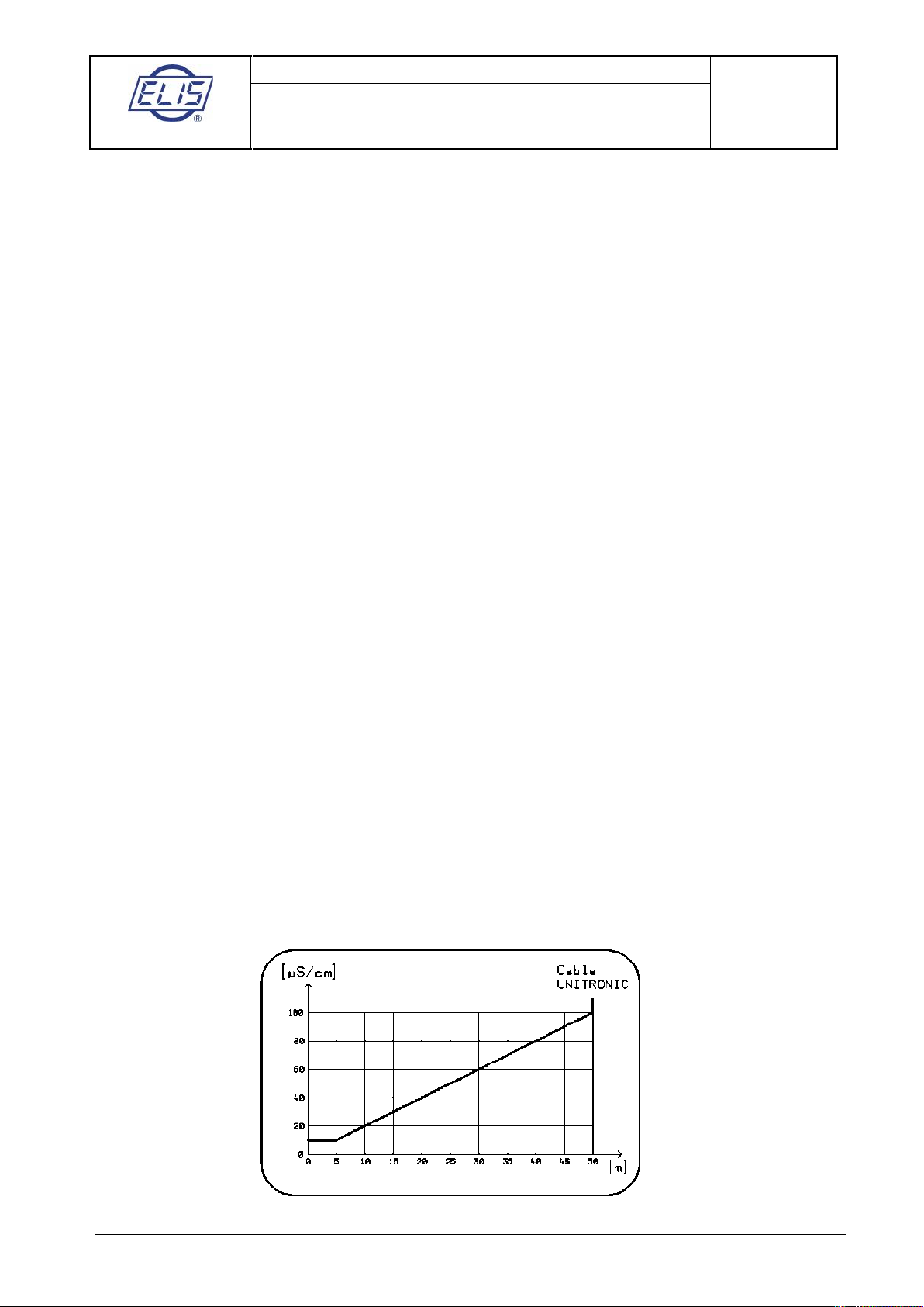
To prevent electromagnetic interference in the connecting cable, the sensor and remote transmitter should
be located as close as possible to one another. The maximum cable length depends on the conductivity of
the measured liquid (see the following diagram).
ELIS PLZEŇ a. s.
Design, Assembly and Service Manual
Page 13 of 69
Electromagnetic flowmeter FLONET FN20xx.1
ELIS PLZEŇ a. s., Luční 425/15, 30100 Plzeň, Czech Republic, Phone: +420/377 517 711, Fax: +420/377 517 722 Es90420K/c
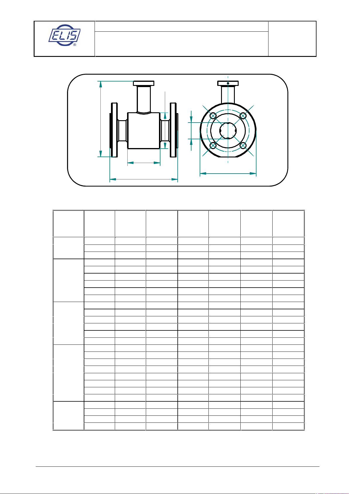
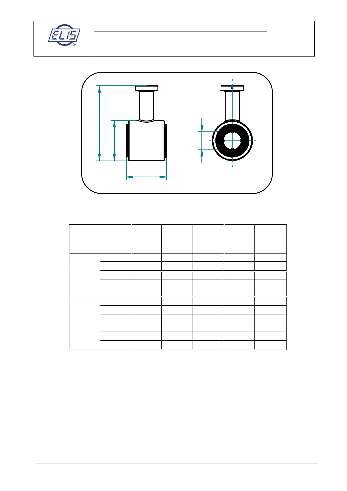
4.1.6. Dimensions of flanged sensor
D
DN
l
L
d
A
Dimensions of sensor with flanges according to EN1092-1.
Pressure
rating
DN
D [mm]
D [mm]
A* [mm]
L [mm]
L [mm]
Weight
[ kg ]
6
90
170
PN 25890
170
10
90
170
159562
164
200
66
2.9
20
10562170
200
66
3
PN 40
25
11572180
200
96
3.9
32
14082197
200
96
5.5
40
15092207
200966.1
50
165
107
225
200968.1
65
185
127
245
2009610
80
200
142
260
200
96
12.3
PN 16
100
220
162
280
2509615.3
125
250
192
310
250
126
18.9
150
285
218
344
300
126
26
200
340
274
399
350
211
36
250
395
370
475
450
211
60
300
445
420
525
500
320
68
350
505
480
584
550
320
92
PN 10
400
565
530
642
600
320
158
450
615
581
695
600
320
150
500
670
640
752
600
320
177
600
780
760
870
600
320
288
700
895
880
990
700
420
800
975
960
1100
800
420
427
PN 6
900
1075
1040
1185
900
520
1000
1175
1140
1290
1000
520
500
1200
1405
1340
1510
1200
520
680
* Dimension A (sensor height) is without transmitter housing (or terminal box in the remote
version).
The sensor weight is an indicative value.

ELIS PLZEŇ a. s.
Design, Assembly and Service Manual
Page 14 of 69
Electromagnetic flowmeter FLONET FN20xx.1
ELIS PLZEŇ a. s., Luční 425/15, 30100 Plzeň, Czech Republic, Phone: +420/377 517 711, Fax: +420/377 517 722 Es90420K/c
Dimensions of sensor with flanges according to ASME (ANSI) B16.5 Class 150 (from 1/2” to 24”) and AWWA
Class B (from 28” to 48”)
Pressure
rating
NPS
D [inch]
D [inch]
A* [inch]
L [inch]
L [inch]
Weight [lbs]
Class 150
(according
to ASME)
1/2"
3,5
2,4
6,3
7,9
2,6
6,6
3/4"
3,9
2,4
6,5
7,9
2,6
6,6
1"
4,3
2,8
6,9
7,9
3,8
6,6
1 1/4"
4,6
3,2
7,3
7,9
3,8
8,8
1 1/2"
5,0
3,6
7,7
7,9
3,8
8,8
2"
6,0
4,2
8,6
7,9
3,8
13,2
2 1/2"
7,0
5,0
9,5
7,9
3,8
19,8
3"
7,5
5,6
10,0
7,9
3,8
30,9
4"
9,0
6,4
11,2
9,8
3,8
35,3
5"
10,0
7,6
12,3
9,8
5,0
41,9
6"
11,0
8,6
13,4
11,8
5,0
55,1
8"
13,5
10,8
15,8
13,8
8,3
90,4
10"
16,0
14,6
18,9
17,7
8,3
119,0
12"
19,0
16,5
21,4
19,7
12,6
169,8
14"
21,0
18,9
23,6
21,7
12,6
202,8
16"
23,5
20,9
25,8
23,6
12,6
255,7
18"
25,0
22,9
27,8
23,6
12,6
330,7
20"
27,5
25,2
30,0
23,6
12,6
368,2
24"
32,0
29,9
34,6
23,6
12,6
694,5
Class B
(according
to AWWA)
28"
36,5
34,0
39,6
27,6
16,5
793,7
32"
41,8
37,7
43,8
31,5
16,5
941,4
36"
46,0
41,7
47,9
0,0
20,5
1124,4
40"
50,8
45,5
52,2
39,4
20,5
1278,7
48"
59,5
54,1
61,1
47,2
20,5
1499,1
* Dimension A (sensor height) is net of the electronic unit box (or terminal box in the remote meter
version).
The sensor weight data are indicative only.
ELIS PLZEŇ a. s.
Design, Assembly and Service Manual
Page 15 of 69
Electromagnetic flowmeter FLONET FN20xx.1
ELIS PLZEŇ a. s., Luční 425/15, 30100 Plzeň, Czech Republic, Phone: +420/377 517 711, Fax: +420/377 517 722 Es90420K/c
4.1.7. Dimensions of flangeless sensor
L
A
D
DN
Dimensions of flangeless sensor
Pressure
rating
NPS
DN [inch]
D [inch]
A* [inch]
L [inch]
Weight
[ lbs ]
¾”
0,8
2,4
6,0
2,9
x1"1,0
2,8
6,4
4,1
3,3
PN 40
1 ¼”
1,3
3,2
6,8
4,1
4,0
1 ½”
1,6
3,7
7,2
4,1
5,32"2,0
4,2
7,9
4,1
5,5
2 ½”
2,6
5,0
8,7
4,1
6,63"3,1
5,6
9,3
4,1
8,2
PN 16
4"
3,9
6,4
10,1
4,1
12,1
5"
4,9
7,6
11,3
5,3
13,26"5,9
8,6
12,4
5,3
17,2
8"
7,9
10,8
14,6
8,6
29,8
* Dimension A (sensor height) is without transmitter housing (or terminal box).
The sensor weight is an indicative value.
Caution: Connection for counter flanges ASME (ANSI) for flangeless version is supplied starting with NPS 1"
to NPS 8".
(Sensors are one dimension smaller due the installation between flanges from NPS 1" up to NPS 3"; for
example: request from customer NPS 1" means sensor with internal diameter NPS 3/4", and it corresponds
with a range of flow rates).
From NPS 4" to NPS 8" sensors are of the same diameters.
Note: The grounding rings for a flangeless version: size of the grounding rings should be the same size as a
size of the existing pipe - valid for EN 1092-1 and ASME (ANSI) standards.

ELIS PLZEŇ a. s.
Design, Assembly and Service Manual
Page 16 of 69
Electromagnetic flowmeter FLONET FN20xx.1
ELIS PLZEŇ a. s., Luční 425/15, 30100 Plzeň, Czech Republic, Phone: +420/377 517 711, Fax: +420/377 517 722 Es90420K/c
4.1.8. Sensor specifications
Sensor size
Flanged sensors, DN 6 to DN 1200 (NPS ½” to 48”)
Flangeless sensors, DN 20 to DN 200 (NPS 3/4” to 8”)
Maximum admissible working pressure
with EN 1092-1 flanges
25 bar at RT* for DN 6 to 10 / PN25
40 bar at RT* for DN 15 to 50 / PN40
16 bar at RT* for DN 65 to 200 / PN16
10 bar at RT* for DN 250 to 750 / PN10
6 bar at RT* for DN 800 to 1200 / PN6
*RT – reference temperature: -10 °C to +50 °C / 14 °F to
122 °F
with ASME(ANSI) B16.5 flanges
230 psig at -20° to +100°F (NPS ½“ to 10“ class 150)
150 psig at -20° to +100°F (NPS 12“ to 24” class 150)
with AWWA flanges
86 psig at -20 °F to +100 °F (NPS 28” to 48” class B)
Mechanical connection
Flanges according to EN 1092-1,
ASME (ANSI) B16.5, AWWA standards
Flangeless
Others
Grounding
on flanges
Grounding rings
Grounding electrode
Flow velocity of measured liquid
From 0.1 m/s to 10 m/s (0.33 to 33 ft/s)
Maximum temperature of measured liquid
up to 110 ºC (230 °F)
up to 150 °C (302 °F) for request
(for detailed information see article 4.1.4)
Minimum conductivity of measured liquid
20 μS/cm, 5 μS/cm in special applications
Empty pipe detection
a) with measurement electrodes from DN50 (2”)
b) for remote version max length of cable 6 m (19,6 ft)
Lining
Soft rubber
Hard rubber
Rubber for drinking water
PTFE
E-CTFE
Measuring electrodes
Stainless steel, grade 1.4571 (316Ti)
Hastelloy C276
Titanium
Tantalum
Platinum-Rhodium (PtRh10)
other materials on request
Protection class
IP 67
IP 68 (2 m / 6,5 ft)
Storage temperature
-10 ºC to +70 ºC (14 °F to 158 °F)
at max. relative air humidity 70 %
(for PTFE, E-CTFE, Soft Rubber)
+5 °C to +70 ºC (41 °F to 158 °F)
at max. relative air humidity 70 %
(for Hard Rubber and Rubber for drinking water)
ELIS PLZEŇ a. s.
Design, Assembly and Service Manual
Page 17 of 69
Electromagnetic flowmeter FLONET FN20xx.1
ELIS PLZEŇ a. s., Luční 425/15, 30100 Plzeň, Czech Republic, Phone: +420/377 517 711, Fax: +420/377 517 722 Es90420K/c
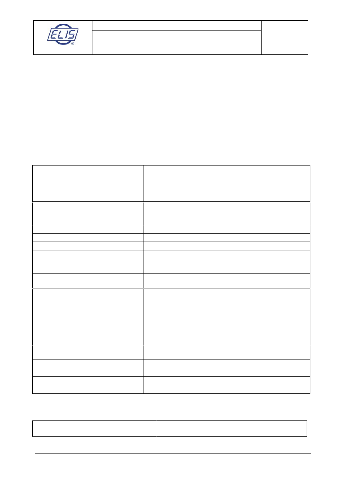
4.2. Transmitter housing
The transmitter is accommodated in a cast aluminium box coated on the surface with paint of hue RAL 1017.
The box is held by four M5 bolts with hexagonal socket heads. Upon loosening the bolts slightly the box can
be rotated around horizontal axis through ±180°. At the rear part of the box there is a terminal board under a
lid held in position by six bolts with hexagonal socket heads. At the bottom of the box there are cable glands
and a special valve preventing condensation of the air humidity inside the box.
The unused gland openings shall be blinded. The front panel of the box is either blinded (the ECONOMIC
version) or fitted with a two-line background-illuminated display unit and a four-button membrane keypad (the
COMFORT version of the meter).
Prior to putting the meter into operation, check the correct sealing of all active glands, blinding of the unused
ones and tightening of the bolts holding the terminal box lid.
4.2.1. Transmitter specifications
Power supply
230V~ (+10 % / -15 %) / 50 to 60 Hz
115V~ (+10 % / -15 %) / 50 to 60 Hz
24V~ (+10 % / -15 %) / 50 to 60 Hz
24V = (± 20 %)
Power consumption
15 VA
Line fuse
T 250 mA, T 2.0 A (with power supply 24 V)
Electric shock protection according to
standard CSN 332000-4-41
Automated disconnection from power source in TN-S network
Housing material
Aluminium casting
Weight
3.0 kg / 6,6 lbs
Ambient temperature
-5 °C to 55 °C / 23 °F to 131 °F (protected from direct sun light)
Storage temperature
-10 °C to 70 °C / 14 °F to 158 °F at relative air humidity not
exceeding 70 %
Flow velocity range
0.1 to 10 m/s (0.33 to 33 ft/s)
Accuracy class according to
EN ISO 4064-1 (OIML R49) *)
2
Zero flow-rate setting
For COMFORT version only
Output 1 - passive output, isolated
Output 2 - passive output, isolated
Active current output, isolated
Dosing: input 1
output 3
Output relay
Binary multi-function optocoupler 30 V / 50 mA
Binary multi-function optocoupler 30 V / 50 mA
Analog 0 (4) to 20mA, max. load 1,000 Ohm
Input optocoupler diode 5 V, 10 mA
Binary multi-function optocoupler 30 V / 50 mA
Insulated switch contact 0.3 A, 30 VDC
Mechanical lifetime 50,000,000 cycles
Serial communication ports
USB (not insulated)
RS-485 (insulated)
Operator communication language
CZ – Czech, EN – English
Protection class
IP 67
ECONOMIC version / configuration
C 6.00 – no display or keypad
COMFORT version / configuration
C 7.00 – including display and keypad
*) in the above standard version it is possible to supply the flowmeter with higher accuracy in the range and
conditions agreed with the manufacturer
Example of above standard parameters:
Maximum measurement accuracy
0,2 % for 10 to 100 % of Q
4
0,5 % for 5 to 100 % of Q
4
ELIS PLZEŇ a. s.
Design, Assembly and Service Manual
Page 18 of 69
Electromagnetic flowmeter FLONET FN20xx.1
ELIS PLZEŇ a. s., Luční 425/15, 30100 Plzeň, Czech Republic, Phone: +420/377 517 711, Fax: +420/377 517 722 Es90420K/c
5. METER APPLICATION RULES
The compact version of flowmeter is intended only for environments without occurrence of condensation and
where media temperature does not exceed +50 °C (122 °F).
5.1. Sensor placement in piping
No chemical injection or batching unit (such as chlorine compound injector) should be located at sensor’s
inlet. The insufficient homogeneity of the flowing liquid may affect the flow rate values indicated by the meter.
The meter performance will be the best if the liquid flow in the piping is well stabilised; therefore it is
necessary to observe specific rules for the sensor placement in piping. In the contact planes between the
sensor and the adjoining piping sections shall be no edges as these would cause flow turbulence. Make sure
that straight piping sections are provided before and after the sensor; their required length is proportional to
the inner diameter of piping.
If more than one flow-disturbing element such as pipe bend or fitting are located near the sensor, the
required length of straight piping section on the sensor side concerned should be multiplied by the quantity
of such elements.
As required by clause 4.2.1 of standard EN 29104, the inner diameter of the connected pipe shall not differ
by more than 3% from that of the sensor.
In the cases of bi-directional flow rate measurement, the same conditions concerning flow stability shall be
met at sensor’s input and output.
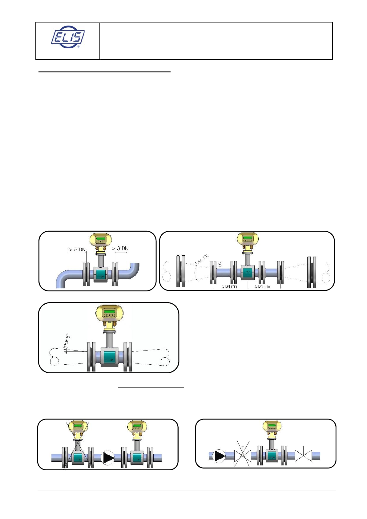
Required straight piping sections Pipe narrowing
Where the pipe size is larger than that of the meter
sensor, it is necessary to use conical reduction pieces
with the angle of taper not exceeding 15° (see the
picture). For a bi-directional flow measurement, the
minimum length of straight piping sections on both
sides is 5 DN. At horizontal sensor installations, to
prevent the occurrence of air bubbles, use
eccentrically-fitted reduction pieces (see standard
EN ISO 6817).
Pipe narrowing sections with angles not exceeding 8° can be taken for straight sections.
Where the liquid is pumped into the piping, the flow sensor shall always be placed at the outlet side of the
pump to prevent under pressure in the piping which might damage the sensor. The required length of the
straight piping section between the pump and sensor is at least 25 DN.
Pump in the piping Closing valve in the piping
ELIS PLZEŇ a. s.
Design, Assembly and Service Manual
Page 19 of 69
Electromagnetic flowmeter FLONET FN20xx.1
ELIS PLZEŇ a. s., Luční 425/15, 30100 Plzeň, Czech Republic, Phone: +420/377 517 711, Fax: +420/377 517 722 Es90420K/c
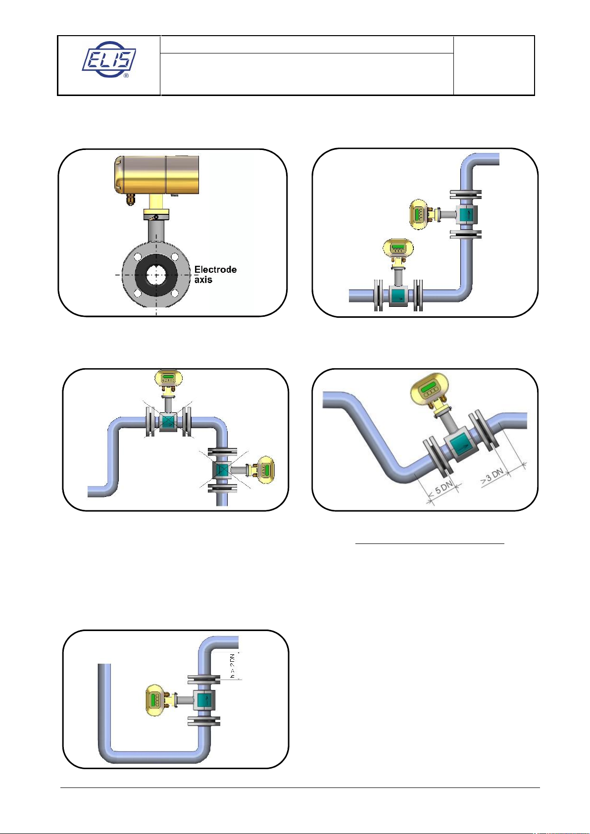
For the same reason, the sensor shall be always placed before the closing valve in the piping.
The sensor can be fitted in the piping in either horizontal or vertical position. Make sure that the electrode
axis is always horizontal and, if the sensor is mounted in a horizontal position, the chimney faces upwards.
Electrode axis Sensor mounted in a vertical position
Where the sensor is mounted in a vertical position, the flow direction shall always be upwards.
Risk of liquid aeration Permanent flooding of sensor
To ensure correct meter function at all times, the measured liquid must completely fill up the sensor and no
air bubbles shall be permitted to accumulate or develop in the sensor tube. Therefore, the sensor shall never
be placed in the upper pocket of the piping or in a vertical piping section where the flow direction is
downwards.
In piping systems where complete flooding of the piping cannot always be guaranteed, consider placing the
sensor in a bottom pocket where full flooding is ensured.
If the sensor is located near a free discharge point, such point shall be by at least 2 DN higher than the top
part of the sensor.
Sensor placement near free discharge point
ELIS PLZEŇ a. s.
Design, Assembly and Service Manual
Page 20 of 69
Electromagnetic flowmeter FLONET FN20xx.1
ELIS PLZEŇ a. s., Luční 425/15, 30100 Plzeň, Czech Republic, Phone: +420/377 517 711, Fax: +420/377 517 722 Es90420K/c
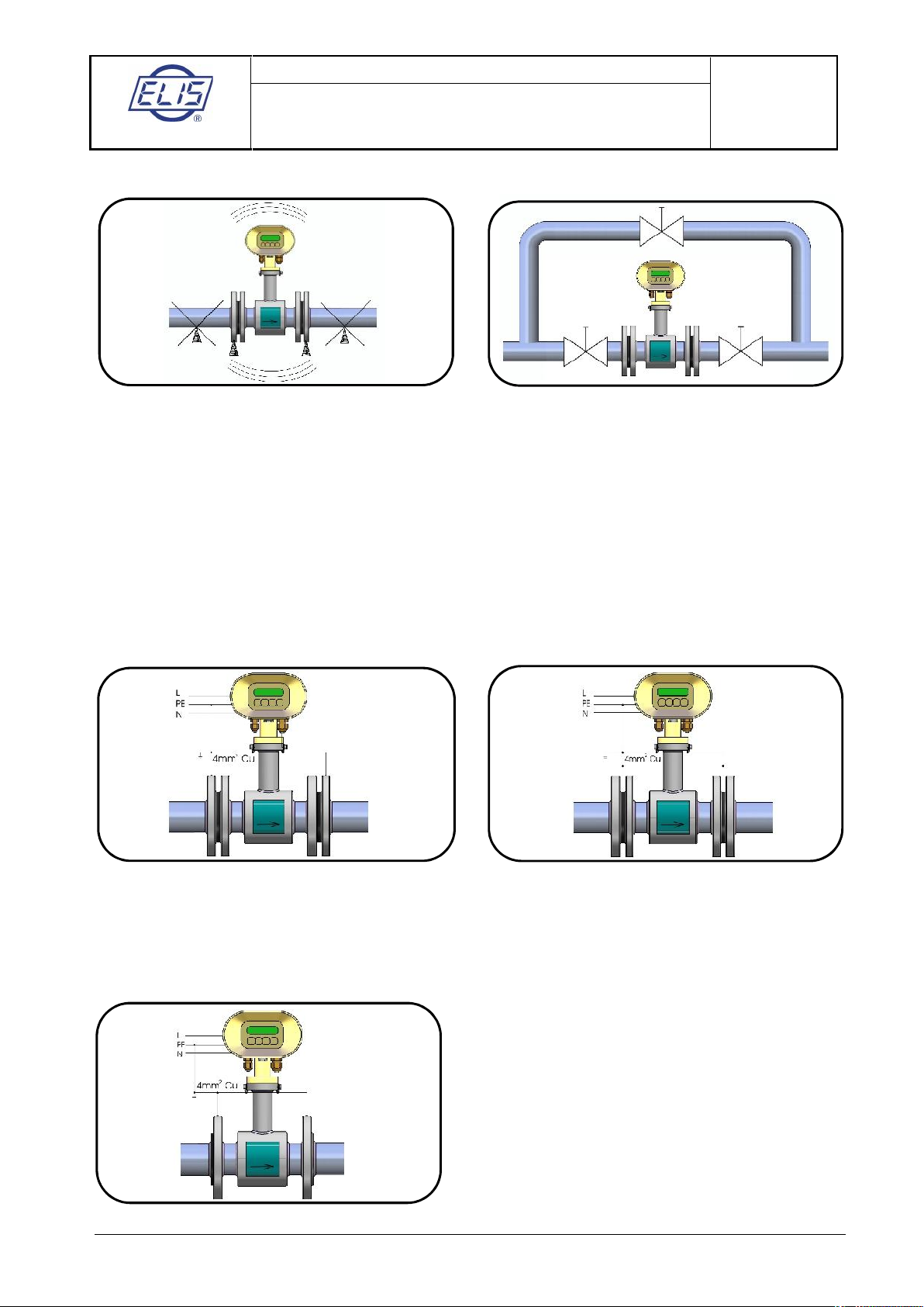
Make sure that the adjoining piping is clamped/supported as close to the sensor as possible, to prevent
vibrations and damage to the sensor.
Undesirable sensor vibrations Sensor bypass
In applications where continuous liquid flow is essential, a bypass shall be provided to allow for sensor
servicing. A sensor bypass may also be a reasonable solution where dismantling the flow sensor would
require an emptying of a very long section of piping.
5.2. Sensor grounding
The correct meter function requires that both sensor and adjoining piping sections are duly interconnected to
the ground potential by low-impedance grounding conductors and a protective conductor from a power
supply. The overall arrangement shall be such that the potentials of the measured liquid at the sensor inlet
and outlet sides are close to the ground.
With a flanged sensor installed in electrically conductive piping, the flanges shall be electrically connected
with the piping and the piping connected to earth.
Flange grounding connection Grounding rings
Should the adjoining piping sections be non-conductive, grounding rings or similar instruments shall be used
to ensure that the electric potential of the measured liquid is properly grounded.
In case of a flangeless sensor, the piping flanges holding the sensor shall be electrically connected with the
grounding point on the sensor.
Flangeless sensor
To ensure potential equalisation for remote version of
flowmeter, it is recommended to interconnect the sensor
body with the transmitter housing with a copper
conductor of cross-section 4mm2.

ELIS PLZEŇ a. s.
Design, Assembly and Service Manual
Page 21 of 69
Electromagnetic flowmeter FLONET FN20xx.1
ELIS PLZEŇ a. s., Luční 425/15, 30100 Plzeň, Czech Republic, Phone: +420/377 517 711, Fax: +420/377 517 722 Es90420K/c
6. FLOWMETER INSTALLATION AND COMMISSIONING
The meter installation shall be performed in a strict observance of rules and procedures as described in this
manual.
To prevent undesirable interference, the power cables shall be laid at least 25 cm away from all signal
cables. The signal cables include the cable connecting the sensor with the transmitter (in case of a remote
meter version), output signal cables and the cable of the RS-485 communication line. All cables shall be laid
outside the thermal insulation layer on the piping (if any). Only shielded conductors shall be used to connect
the output signals and the RS-485 line where the shielding shall be connected to the earth potential on the
side of the master control system.
In applications where high levels of electromagnetic field interference at the measuring location can be
expected (e.g. in the vicinity of power frequency converters), the remote meter version should be avoided. In
these cases it is also recommended to include a filter in the power supply line to the transmitter.
Filter specification: The filter is intended to suppress dissemination of the undesirable high frequency
disturbances from the power supply cable to the flowmeter system. Use any commercial filter of suitable
parameters including protection class, and install it is close to the meter as possible. If need be, the filter can
be placed in a special protection housing. When installing the filter, observe the applicable safety
regulations.
Rated voltage: 250V/50Hz
Rated current: 0.5A and more
Suppression characteristic: 10kHz: 10 to 20dB
10MHz: 40dB
6.1. Sensor installation
The measurement point chosen for the sensor installation should ensure that the internal part of the sensor
is fully flooded with the measured liquid at all times. If the sensor is mounted in vertical position, the only
permitted liquid flow direction is upwards. No thermal insulation shall be used on the sensor body.
If the flow meter is to be installed in a pipeline with thermal insulation, the insulation shall be removed at the
sensor insulation point.
The internal diameters of the piping, connecting flanges and the sensor tube shall be identical. The flange
faces shall be perpendicular to the piping. The inlet and outlet piping sections including seals shall be
perfectly aligned, with no protruding edges. In case of a non-conductive piping, use grounding rings on both
sides of the sensor.
The arrow on the sensor body indicates the required liquid flow direction (positive flow direction).
Upon loosening the four bolts holding the transmitter housing in position on the sensor body, the housing can
be rotated through ±180°. The same system for the housing rotation can be used if the housing is mounted
on a bracket attached to a vertical support plate or wall.
Do not expose the transmitter housing to direct sunlight; if installed outdoors, use a suitable protection
shield.
 Loading...