

Elios4you Power Reducer Quick Manual
®
Quick
Guide
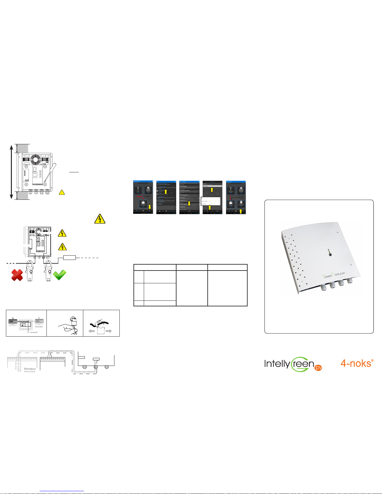
1 Power Reducer
POWER REDUCER
Serial Number from 101
Page 1
Page 5
Page 6
Rev. 1.8 062014
1
INSTALLATION
1) Fix Power Reducer onto the wall.
4) Connect Elios4you and Power Reducer using the 0-10V output
1617 18
IN (0-10V)
Out (0-10V)
GND (0-10V)
1 2 3
0-10V connection
SETTING
5) Power up Elios4you (Power Reducer still off) and complete the
Elios4you set up (Check out Elios4you manual)
Drill the wall referring to the 4 holes at the back of Power Reducer. Use the screws to securely
x it on the wall.
+ 10V
Ctrl
GND
Terminal 2
WARNING: Make sure the power / energy readings are correct. Failure to ensure correct power
/ energy readings will result in incorrect function of the Power Reducer
6) Set up the Power Reducer parameters, using the Elios4you App
open on the tablet / smartphone (Power Reducer still off)
A) From the “Energy Performance” page, press the “Menu” button and go to “Parameter Settings /
Peripherals”. Select “Power Reducer” mode, and enter parameters Load (W) and “Set Point” (W)
B) Now the main page shows the Power Reducer widget. Click the button to access the menu.
7) Switch on the Power Reducer and complete the set up
A) Switch on the Power Reducer and the immersion. Make sure the App keeps the load off
B) Set “Boost” Mode on the APP and set 100% load activation. Click “OK”
C) Make sure the immersion is actually working at full power
D) Set “Automatic” Mode. Now the system will bring the “Exchanged Power” value to the “Set
Point” value, diverting any excess power towards the immersion controlled by Power Reducer
Check the Power Reducer APP Guide to nd out more about the Power Reducer specic features.
MIN 7 cm
MIN 7 cm
LOCATION: the ideal position to install Power Reducer is beside Elios4you, therefore next to the electrical
panel or fuse box. When searching for where to install
the PR, consider that it should be placed near the device power supply.
VENTILATION: In order to provide Power Reducer
with a good ventilation and reduce the operating temperature, it is strongly recommended to install the
device vertically (cable glands must be placed downwards).
Proper ventilation is also guaranteed by clearings
around the device. Make sure no other objects are
placed within a range of 7 centimeteres.
!
ATTENTION: do not use Power Reducer itself as
a template for drilling holes directly on the wall.
2) Cut the immersion power supply cable and connect the pins to the
correct terminals.
WARNING: before cutting the wire, make sure the boiler is not supplied.
Towards the
immersion
Towards the power supply
3) Install Elios4you
See the documentation related to Elios4you for a more detailed installation procedure
Install Elios4you within the main electrical box. If not possible, add an additional electric panel.
a)
b)
I) Identify the live-phase wire
related to PV GENERATION
II) Identify the GENERATION
Curent Transformer
III) Correctly clamp the CT over
the correct live-phase cable
Install the Elios4you Current Transformers
Power Supply cables must be tripolar.
Each single wire must feature a minimum dimension of 2.5 mm
2
Installation of 16 A Circuit Breaker to protect
the device
16 A
Possible measurements made with amperometric clamps must be detected on
the live-phase that connects the power
source with the Power Reducer. Measurements detected on the wire directed towards the resistive load will be inaccurate.
Terminal 1
Terminal 3
Scambio
(rete ENEL)
Produzione
Utenza
green point
Mains meter
(GRID)
Generation
Household
residual-current
circuit breaker
meter
L1
Generation CT:
WHITE label
131415
IN (0-10V)
OUT (0-10V)
GND (0-10V)
Elios4you
single-phase
Elios4you
three-phase
Power Reducer
POWER REDUCER: self-diagnosis
Blinking light - energy detected
by CT: the higher the blink frequency = the bigger the energy
measured
blinking light - quantity of energy, supplied by Power Reducer to the immersion:
the higher the blink frequency
= the bigger the energy diverted
to the immersion
Either ON or OFF
Power Reducer operates in
the proper way
Installation completed successfully
LED behaviour
Functioning
Suggestions
When switch on, Power Reducer begins a test to evaluate the correct KIT installation.
GREEN
YELLOW
RED
When the red LED is steady
ON it informs that ByPass
is active: maximum energy
sent to the immersion, despite of the generated
energy
4-noks
Via Per Sacile, 158 - Francenigo di Gaiarine (TV) - Italy
Tel. (+39) 0434 768462 - Fax (+39) 0438 694617 - info@4-noks.com - www.4-noks.com

INSTALLATION SCHEME into the MAIN electrical panel
Page 4
Page 3
Page 2
Generation CT
Power Reducer - Terminals
Terminal 1 - Towards resistive load (up to 3 kW)
Terminal 3 - Power supply
Terminal 2 - Connections with Elios4you
Terminal 4 - OPTIONAL supply E4U
1
2
3
1
2
3
1
2
3
1
2
3
Power Reducer - LEDs and button
Power Reducer - Wire connections
(Serial Number from 101)
A (resistive load PIN 1)
B (resistive load PIN 2)
+10V
Ctrl
GND
N (neutral)
GND
L (phase @ 230V)
L (phase @ 230V)
GND
N (neutral)
+10 V
Ctrl
GND
Terminal 1
+10 V
Ctrl
GND
A
B
16A Circuit
Braker
Cat. FF
L
GND
L
N
N
GND
Terminal 3
Terminal 4
OPTIONAL
supply E4U
Firmware
version
Terminal 2
Towards immersion
(resistive load ONLY)
16A
circuit breaker
Towards
power supply
ATTENTION: Tripolar wire
Minumum dimension: 2,5 mm
2
Towards Elios4you
0-10V input
!
WARNING: do not connect any wires on TERMINAL 1 other than the 2 wires (A and B) that
supply the resistive load. Any different wiring (eg. sharing A, B with L, N) will cause an internal
electrical damage!
Green
Yellow
Red
Button
Amount of energy passing through the CT
Amount of energy supplyed to the immersion by the Power Reducer
(expressed in %)
Bypass activated (manual boost or by the optional bypass switch)
Pressing the button will turn the immersion on for 1 hour, despite of the
amount of energy sold to the GRID (By-Pass)
Household
L
N
L
L
N
Generation
meter
Mains meter
Towards the
mains meter
Green point
Towards the
residual-current
circuit breaker
Pantone 368C
C=57 M=0 Y=100 K=0
Pantone 158C
C=0 M=61 Y=97 K=0
Grigio 70%
C=0 M=0 Y=0 K=70
Nero
C=0 M=0 Y=0 K=0
N
Power Reducer
Immersion
16A
GRID
Inverter
WARNING: CT orientation
!
K
L
Arrow and “L” pointing
towards the
residual-current
circuit breaker
Mains CT
Power supply
connection
Power supply
connection
MAIN electrical panel
OR
1A
0-10V connection
with Elios4you
 Loading...