

Elington ANT54AV5WCR Installation Manual
Installation Guide
F.P.O.
For Placement Only
For Model:
READ THESE INSTRUCTIONS AND
SAVE THEM FOR FUTURE USE
F. P.O.
For Placement Only
ANT54AV5WCR
Table of Contents:
Safety Tips. pg. 1
Unpacking Your Fan. pg. 2
Parts Inventory. pg. 2
Installation Preparation. pg. 3
Hanging Bracket Installation. pg. 3
Fan Assembly. pgs. 4 - 5
Wiring. pgs. 5 - 6
Canopy Assembly. pg. 7
Scroll Arm Assembly. pg. 7
Blade Assembly. pg. 8
Switch Housing Assembly. pg. 8
Wall Control Operation. pg. 9
Testing Your Fan. pg. 9
Troubleshooting. pg. 10
net weight of fan: 37 lb. (16.78 kg)
Parts Replacement. pg. 10
Warranty. pg. 10
PRINTED IN CHINA

SAFETY TIPS.
WARNING: To reduce the risk of electrical shock, turn off the electricity to the fan at the main fuse box or circuit
panel before you begin the fan installation or before servicing the fan or installing accessories.
1. READ ALL INSTRUCTIONS AND SAFETY INFORMATION CAREFULLY BEFORE INSTALLING YOUR FAN
AND SAVE THESE INSTRUCTIONS.
CAUTION: To avoid personal injury, the use of gloves may be necessary while handling fan parts with sharp
edges.
2. Make sure all electrical connections comply with Local Codes or Ordinances, the National Electrical Code,
and ANSI/NFPA 70-1999. If you are unfamiliar with electrical wiring or if the house/building wires are
different colors than those referred to in the instructions, please use a qualified electrician.
3. Make sure you have a location selected for your fan that allows clear space for the blades to rotate, and at
least seven (7) feet (2.13 meters) of clearance between the floor and the fan blade tips. The fan should
be mounted so that the tips of the blades are at least thirty (30) inches (76 centimeters) from walls or
other upright structures.
4. The outlet box and ceiling support joist used must be securely mounted, and capable of supporting at
least 50 pounds (22,68 kilograms). The outlet box must be supported directly by the building structure.
Use only UL listed outlet boxes marked "FOR FAN SUPPORT."
WARNING: To reduce the risk of fire, electrical shock, or personal injury, mount to the outlet box marked
"Acceptable for Fan Support of 22.68 kg (50 lbs) or less," and use the mounting screws provided with the outlet
box. Most outlet boxes commonly used for the support of lighting fixtures are not acceptable for fan support
and may need to be replaced. Consult a qualified electrician if in doubt.
WARNING: To reduce the risk of fire, electrical shock, or personal injury, wire connectors provided with this fan
are designed to accept only one12 gauge house wire and two lead wires from the fan. If your house wire is larger
than 12 gauge or there is more than one house wire to connect to the corresponding fan lead wires, consult an
electrician for the proper size wire connectors to use.
5. Electrical diagrams are for reference only. Light kits that are not packed with the fan must be UL listed and
marked suitable for use with the model fan you are installing. Switches must be UL general use
switches. Refer to the instructions packaged with the light kits and switches for proper assembly.
6. After installation is complete, check that all connections are absolutely secure.
7. After making electrical connections, spliced conductors should be turned upward and pushed carefully up
into the outlet box. The wires should be spread apart with the grounded conductor and the
equipment-grounding conductor on opposite sides of the outlet box.
WARNING: To reduce the risk of electrical shock or fire, do not use this fan with any solid state speed control
device or control fan speed with a full range dimmer switch. [Using a full range dimmer switch to control fan
speed will cause a loud humming noise from fan.]
8. Do not operate the reverse switch until fan has come to a complete stop. [Note: If using remote control
with reverse capability, reverse fan blade direction only when on LOW speed.]
9. Do not insert anything between the fan blades while they are rotating.
WARNING: To reduce the risk of personal injury, do not bend the blade arms during assembly or after
installation. Do not insert objects into the path of the blades.
WARNING: To avoid personal injury or damage to the fan and other items, be cautious when working around or
cleaning the fan.
10. Do not use water or detergents when cleaning the fan or fan blades. A dry dust cloth or lightly dampened
cloth will be suitable for most cleaning.
WARNING: To reduce the risk of personal injury, use only parts provided with this fan. The use of parts OTHER
than those provided with this fan will void the warranty.
NOTE: The important safety precautions and instructions appearing in the manual are not meant to cover all
possible conditions and situations that may occur. It must be understood that common sense and caution are
necessary factors in the installation and operation of this fan.
page 1
1. Unpacking Your Fan.
Carefully open the packaging. Remove items
from Styrofoam inserts. Remove motor housing
and place on carpet or Styrofoam to avoid
damage to finish. Do not discard fan carton or
Styrofoam inserts should this fan need to be
returned for repairs.
Check against parts inventory that all parts have
been included.
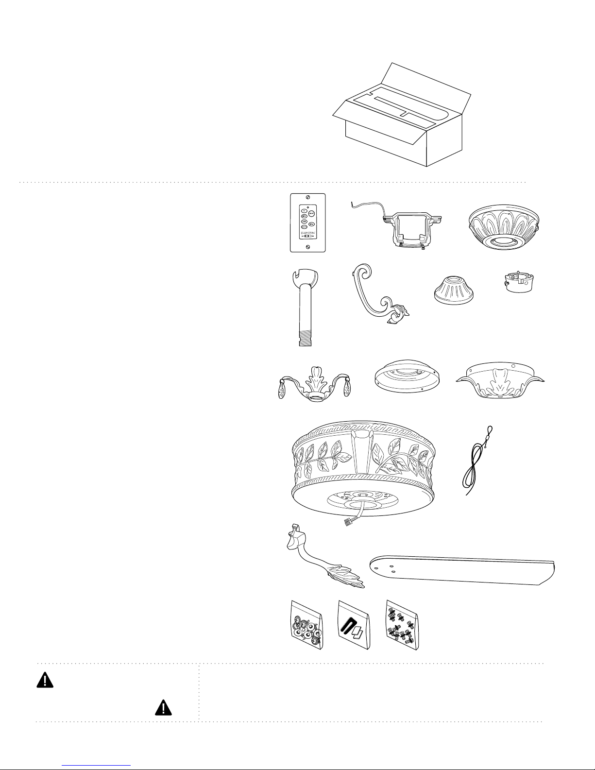
2. Parts Inventory.
a. wall control and plate. 2 separate pieces
b. hanging bracket. 1 piece
c. canopy. 1 piece
d. 12in. downrod and hanging ball. 1 piece
e. scroll arm. 3 pieces
f. yoke cover. 1 piece
g. scroll arm support. 1 piece
h. decorative downrod collar. 1 piece
i. switch housing plate. 1 piece
j. switch housing. 1 piece
a
d
h
k
b
e
i
f
c
g
j
l
k. motor housing. 1 piece
l. safety cable (already attached to motor).
m. blade arm. 5 pieces
n. blade. 5 pieces
o. hardware packs
IMPORTANT REMINDER: You must
use the parts provided with this fan for
proper installation and safety.
1 piece
mn
o
page 2
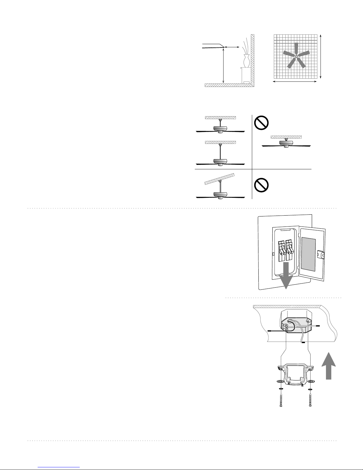
3. Installation Preparation.
blade edge
To prevent personal injury and damage,
ensure that the hanging location allows the
blades a clearance of 7ft. (2.13m) from the
floor and 30in. (76cm) from any wall or
obstruction.
This fan is suitable for room sizes up to 400
square feet (37.2 square meters).
This fan can be mounted with a downrod
on a regular (no-slope) or vaulted ceiling. The
hanging length can be extended by
purchasing a longer downrod (0.5in./1.27cm
diameter). Other installation, such as
flushmount, is not available for this fan.
Installation requires these tools:
Phillips screwdriver, flathead screwdriver,
adjustable pliers or wrench, stepladder, wire
cutters, and rated electrical tape.
4. Hanging Bracket Installation.
4. Hanging Bracket Installation
30
inches
7 feet
(2.13m)
(76cm)
downrod
installation
12ft. - 20ft.
(3.66m - 6.1m)
flushmount
installation
Vaulted ceiling
angle is not to
exceed 25 degrees.
12ft. - 20ft.
(3.66m - 6.1m)
Turn off circuit breakers to current fixture from breaker panel
and be sure operating light switch is turned to the OFF
position.
WARNING: Failure to disconnect power supply prior to
installation may result in serious injury.
Remove existing fixture.
WARNING: To reduce the risk of fire, electric shock, or personal
injury, mount to outlet box marked "Acceptable for Fan Support
of 22.68 kg (50lbs) or Less" and use mounting screws provided
with the outlet box. Most outlet boxes commonly used for the
support of lighting fixtures are not acceptable for fan support
and may need to be replaced. Consult a qualified electrician if in
doubt. When using an existing outlet box, be sure the outlet box
is securely attached to the building structure and can support
the full weight of the fan. Ensure outlet box is clearly marked
"Suitable for Fan Support." If not, it must be replaced with an
approved outlet box. Failure to do so can result in serious injury.
Install hanging bracket to outlet box, using original screws,
spring washers and flat washers provided with new or
original outlet box.* If installing on a vaulted ceiling, face
opening of hanging bracket towards high point of ceiling.
Arrange electrical wiring around the back of the hanging
bracket and away from the bracket opening.
hanging bracket
flat washers
spring washers
outlet box screws
ON
ON
OFF
OFF
*Note: It is very important that you use the proper hardware
when installing the hanging bracket as this will support the
fan.
page 3

5. Fan Assembly.
If you wish to extend the hanging length of your fan,
you must remove the hanging ball from the 12in.
downrod provided to use with an extended downrod
(sold separately). [If you wish to use the 12in. downrod,
please proceed to instructions following the short dotted
line below.]
To remove the hanging ball, loosen set screw on
hanging ball, lower hanging ball and remove stop pin.
Slide hanging ball off of original downrod, A, and slide it
down the longer downrod, B (the top of the downrod
should be noted as having a set screw hole; use this hole
when setting the set screw). Insert stop pin into top of
extended downrod and raise hanging ball. Be sure stop
pin aligns with slots on the inside of the hanging ball.
Tighten set screw securely.
Remove vice from safety cable by loosening the screw
and nut on the vice.
Tip: To prepare for threading electrical wires through
downrod, apply a small piece of electrical tape to the
ends of the electrical wires--this will keep the wires
together when threading them through the downrod.
set screw
A
electrical wiring
downrod
set screw hole
stop pin
hanging ball
B
safety cable
vice
Loosen yoke set screws and nuts at top of motor and
remove pin and clip from yoke at top of motor. Be sure set
screw in scroll arm support is loosened and that notches in
scroll arm support face upward. Slide downrod through
canopy, decorative downrod collar, scroll arm support
and yoke cover.
Thread safety cable and electrical wires through
downrod and pull extra wire slack from the upper end of
the downrod.
Thread downrod into the motor housing yoke until holes
for pin and clip in downrod align with holes in
yoke--make sure wires do not get twisted. Re-insert pin and
clip that were previously removed. Securely tighten yoke
set screws and nuts. Lower yoke cover to motor housing.
Remove blade arm screws and lock washers from
underside of motor and then remove stabilization plate.
Important: Stabilization plate may be discarded once
removed but save blade arm screws and lock washers for
later use.
["Fan Assembly" continued on next page.]
NOTE: The important safety precautions and instructions
appearing in the manual are not meant to cover all possible
conditions and situations that may occur. It must be
understood that common sense and caution are necessary
factors in the installation and operation of this fan.
pin
canopy
scroll arm
support
blade arm
screws and
lock washers
decorative
downrod
collar
yoke cover
clip
yoke set screw
motor housing
stabilization plate
page 4

5. Fan Assembly. (cont.)
Tip: Code switches in the first part of Section 6
can be set on the top of the motor housing prior
to hanging the fan.
With the hanging bracket secured to the outlet
box and able to support the fan, you are now
ready to hang your fan. Grab the fan firmly with
two hands. Slide downrod through opening in
hanging bracket and let hanging ball rest on the
hanging bracket. Turn the hanging ball slot until it
lines up with the hanging bracket tab.
WARNING: Failure to align slot in hanging ball
with tab in hanging bracket may result in serious
injury or death.
Suggestion: Seek the help of another person to
hold the stepladder in place and to lift the fan up
to you once you are set on the ladder.
Find a secure attachment point (wood ceiling joist
highly recommended) and secure the safety
cable. It will be necessary to use a heavy duty
wood screw, washer and lock washer (not
supplied) with the safety cable loop. Extra cable
slack can be left in ceiling area.
wood
ceiling
joist
safety cable loop
wood screw
and washer
screw
nut
safety cable
hanging bracket tab
hanging ball slot
motor housing
Replace vice on safety cable and adjust safety
cable length by pulling on the cable. Adjust slack
in cable to a hands length and secure vice by
tightening screw and nut securely. [Refer to
drawing at right.] The loop at the end of the safety
cable should just fit over the threads on the wood
screw. Test safety cable by pulling on loose end with
pliers. If the safety cable slips, the vice and nut must
be set tighter.
6. Wiring.
Use a ballpoint pen or a small screwdriver to set
the code switches for the wall control, and
built-in receiver so that they match. Factory
setting is pre-set and not recommended for use. If
your wall control interferes with other appliances,
change to another matching code on the wall
control and built-in receiver.
wall control
code switches
motor housing
1
2
4
3
["Wiring" continued on next page.]
page 5

green/
bare
ground
6. Wiring. (cont.)
CAUTION: Be sure outlet box is properly grounded
and that a ground (GREEN or Bare) wire is present.
Make sure all electrical connections comply with
Local Codes or Ordinances and the National
Electrical Code. If you are unfamiliar with electrical
wiring or if the house/building wires are different
colors than those referred to in the instructions,
please use a qualified electrician.
Note: Excess lead wire length from the fan can be
cut to the desired length and then stripped.
When downrod is secured in place on the
hanging bracket, electrical wiring can be
made as follows:
Connect BLACK wire from fan to BLACK wire
from ceiling with wire connector provided.
Connect WHITE wire from fan to WHITE wire
from ceiling with wire connector provided.
Connect all GROUND (GREEN) wires together
from fan to BARE/GREEN wire from ceiling with
wire connector provided.
from ceiling
from fan
white supply wire
black supply wire
black
white
white
black
ground
(green or bare)
ground
(green
or bare)
*
* Wrap each wire connector separately with
electrical tape as an extra safety measure.
IN ORDER TO WIRE WALL CONTROL, remove
existing wall switch.
After codes have been properly set according to
"Wiring" instructions on previous page, wire the
WALL CONTROL with wire connectors provided
as shown in diagram at right.
* Wrap each wire connector separately with
electrical tape as an extra safety measure. Gently
push wires and taped wire connectors into outlet
box.
Attach wall control to outlet box and secure with
screws from original wall switch. Attach front
plate to wall control using 2 screws provided in
the wall control.
outlet box
breaker box)
green/
ground
ground
black
(AC IN from
green/
bare
bare
black
wall
control
1
2
3
green
black (OUT to fan)
black
(TO POWER supply)
4
plate
code
switches
page 6
 Loading...