

ELINEX EL250, EL1000 User Instructions
SPECIFICATIONS
Model EL250 EL1000
Output Rating @ 230V (VA) 250 1000
Output Current Rating (Amps) 1.1 4.35
Input Voltage (VAC) 200-240 200-240
Input Frequency (Hz) 50-60 50-60
Operating Temperature 0-30 0-30
(non-condensing) °C
Output Voltage (VAC) As Input As Input
Load Regulation ±3% ±1,5%
Inrush Capacity – ½ cycle (Amps) 35 150
Inrush Capacity – 1 sec (Amps) 9 25
Inrush Capacity – 10 secs (Amps) 5 17
Forward Transfer Impedance @ 1kHz 25 Ω 11 Ω
Output Current Crest Factor for 10% (max) drop in peak voltage 3 3
Efficiency at 80% load 92% 95%
Earth Leakage Current (typical) (µA) 50 75
50-ohm Attenuation
Normal-Mode 100kHz 60dB 60dB
Normal-Mode 30kHz-30MHz >40dB >40dB
Common-Mode 0-1MHz >60dB >60dB
Common-Mode 0-30MHz >30dB >30dB
0.1µs/100kHz 6kV Ring-Wave attenuation NM < 6V < 6V
0.1µs/100kHz 6kV Ring-Wave attenuation CM < 1V < 1V
Ground-Watch ® Impedance >500 Ω >500 Ω
10KHz-10MHz
Output receptacle type IEC320 IEC320
Number of Output Receptacles 1 4
Size w x d x h (mm) 222x160x130 306x230x180
Wall-mount screw spacing (mm) 120 190
Weight (net) (kg) 5.25 19
Fuse 20x5mm HBC (ceramic) Type T 3.15A 10A
©
Elinex Power Solutions b.v.
www.elinex.com 3516 Iss 5
Low Impedance
POWER CONDITIONER
USER INSTRUCTIONS
The Elinex Low Impedance AC Power Conditioner provides
super-clean electrical power to sensitive electronic
equipment. Unlike ordinary power conditioners, its
low transfer impedance does not restrict the harmonic
currents taken by modern switchmode power supplies,
and its low output impedance does not magnify the
levels
exported
equipment. It is capable of supplying the full inrush
and surge currents taken by many types of equipment
and therefore does not have to be de-rated for some
applications. Unlike ordinary power-line filters, its wide
bandwidth and non-saturable magnetic characteristics
ensure effective elimination of noise and transient
surges across the entire spectrum, and up to 6 kilovolts
in amplitude.
The Elinex AC Power Conditioner provides a special
“Local Clean Earth” independent of the signal quality of
the building’s electrical safety earth system.
noise always present in your own
www.elinex.com
ELX_manual_148x210mm.indd 1-2ELX_manual_148x210mm.indd 1-2 13-02-2009 15:39:3713-02-2009 15:39:37
RATINGS
INSTALLATION
OPERATION
The product’s continuous rating in VA is indicated on the rating plate, and
in Amps adjacent to the socket-outlet(s). The continuous load current must
not exceed this figure, although short-term surge overloads are permissible
(refer to specifications).
To verify that the rating is appropriate for your application, add up the
consumption of the equipment which is to be supplied by the Power
Conditioner, by referring to their rating plates. When a more accurate
method is required, the current consumption of your equipment can be
obtained by measurement. Ensure that a TRUE-RMS meter is used for this
purpose, as ordinary meters will give a totally erroneous measurement.
The unit is suitable for mounting on a horizontal surface, such as the floor or
a desk, or on a vertical surface such as a wall. For units with a factory-fitted
power lead, the socket-outlet which is to supply the unit should be within
reach of the unit (approx. 1,75m), and should be easily accessible.
WARNING: The unit must be operated from a socket incorporating a safety
earth.
The unit should be located as close as possible to the equipment which it
is to supply, and power leads from the unit to the equipment should not be
routed adjacent to other “dirty” power wiring.
Ensure that the location selected does not restrict ventilation around the
unit. If used on a horizontal surface, the unit should always stand on
its feet. For wall-mounting, the unit is suspended from the keyhole slots
provided. The keyhole slots will fit over two 5mm screws (see specifications
for spacing). Additional screws through other mounting holes may be used
if required.
WARNING: Any other orientation, whether wall-mounted or free-standing,
may impede ventilation and invalidates safety certification.
Simply connect the unit to a suitable supply, and connect your equipment to
the output receptacle using a suitable lead with IEC connector, and operate
as normal. The unit has no ON/OFF switch.
It is not necessary to disconnect the unit when the load equipment is not
in use. The unit has extremely low standby power consumption and may be
left connected continuously.
To ensure optimum protection for your equipment, all equipment connected
locally to your system should be operated from the same conditioned source;
for example, in a typical computing application, the processor, screen,
printer and modem should all be connected through the Power Interface.
Protecting only some of the components might affect your system as a result
of transient noise entering the protected equipment via (for example) an
interconnecting data cable; the so-called “back-door hit”.
REFERENCE
GROUND TERMINAL
GROUND-WATCH
®
DEALING WITH
PROBLEMS
In order for all systems to benefit from the “Local Clean Earth” provided
by the Elinex Power Conditioner, the unit is fitted with a Reference Ground
terminal adjacent to the socket-outlet. Ancillary items normally separately
grounded to your equipment, such as logic reference grounds, data line
screens, static control equipment, etc., may be connected to this terminal.
Note: If not required for such purposes, it should be left un-connected.
It should not be connected to other electrical earths, such as the building
safety earth, water pipes, etc.
Units with part numbers with suffix "GW" are equipped with a special filter
which isolates your equipment from local ground noise, whilst not affecting
the safety earth. This may be especially effective in networked installations
where noise is carried on data lines from remote systems, or where there are
high levels of locally induced noise, for example from machinery or electronic
fluorescent lighting units.
Your Elinex Power Conditioner has been designed for many years of troublefree operation. In the unlikely event of problems, follow this procedure:
1. Use a proprietary socket tester to verify that voltage is present at
the power socket which supplies the Power Conditioner, and confirm
that it is
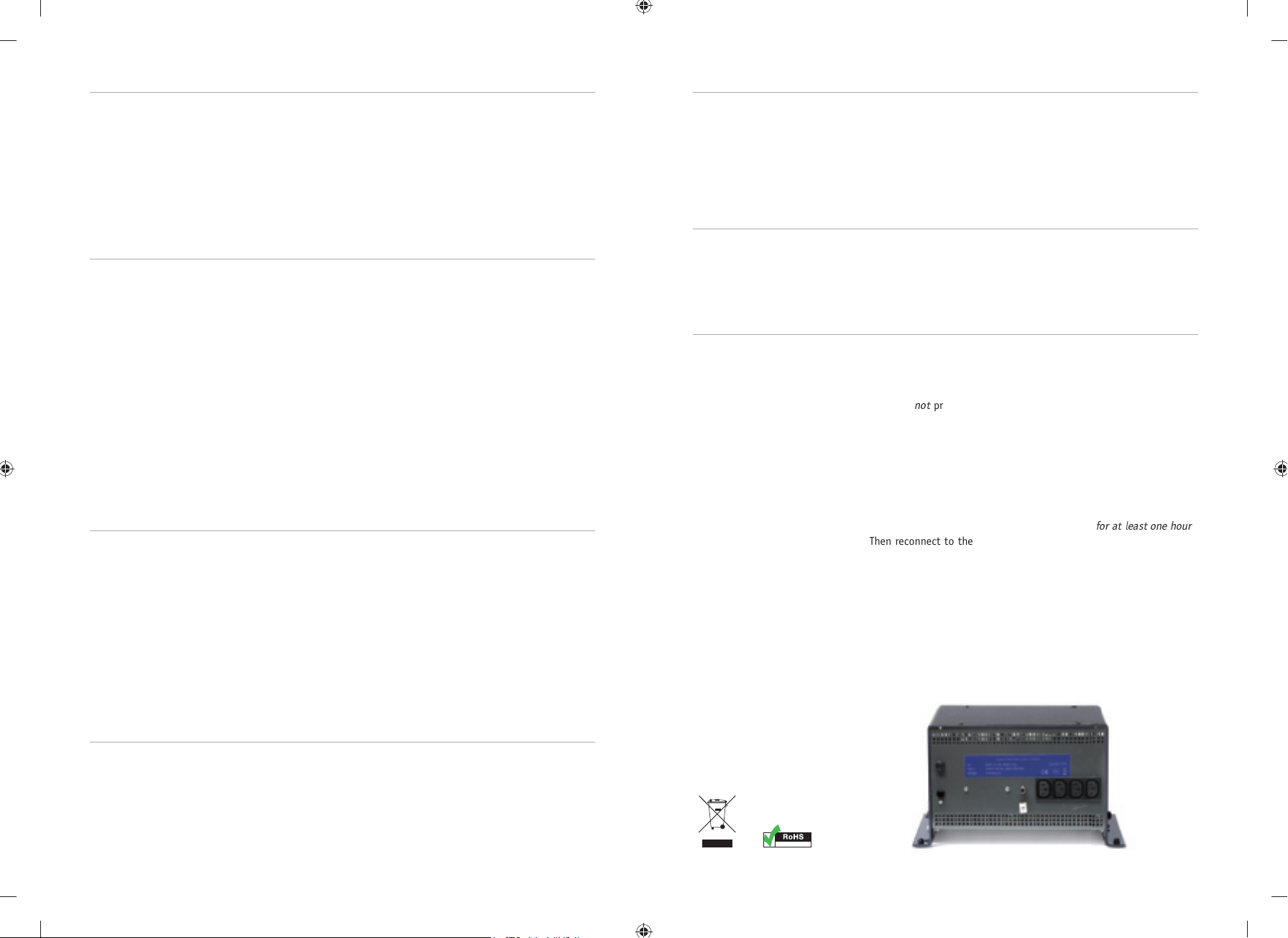
2. Check that the power fuse on the unit has not operated. Use a
screwdriver to remove the cap of the fuseholder, and withdraw
the fuse. Test the fuse with a proprietary fuse tester or multimeter.
If it has blown, replace only with a HBC (ceramic) 20x5mm type
T fuse of rating as indicated on the label adjacent to the fuseholder.
Locate and correct the cause of the fault prior to re-connecting
3. Check that the thermal trip has not operated. Disconnect from the
supply and the load, and allow the unit to cool
Then reconnect to the supply and test again for voltage at the
socket-outlet on the unit. If the unit has recovered, then locate and
correct the cause of the overload condition prior to re-connecting.
If the unit is still not operating, refer to your supplier for advice on how to
return the unit for repair.
WARNING: DO NOT ATTEMPT TO REMOVE THE COVER OF THE UNIT. Live parts
at hazardous voltage may be exposed. The unit contains no user serviceable parts.
not
present at the socket-outlet of the Power Conditioner.
for at least one hour
.
OVERLOAD
PROTECTION
ELX_manual_148x210mm.indd 3-4ELX_manual_148x210mm.indd 3-4 13-02-2009 15:39:4113-02-2009 15:39:41
The unit incorporates two systems to protect from overloads.
Moderate overloads, such as caused by an incorrectly rated load, will, after a
long delay, operate a thermal trip, which switches off the load. Once the unit
has cooled down, reset is automatic on units up to 500VA, but the 1000VA
must be disconnected momentarily from the supply. High overloads, such as
caused by accidental short-circuits, will cause the panel-mounted fuse to
blow. The fuse must be replaced with the same type.
COMPLIANT
 Loading...