

Page 1

Renogy Charge Controller Model No. PWM10CC
1
30 AMP PWM CHARGE CONTROLLER MANUAL
Technical Information (12/24V Auto Mode)
12V
24V
• Rated Solar Input
• Related Load
• 25% Current Overload
1 minute
1 minute
• Load Disconnect
22.2V
• Load Reconnect
12.6V
25.2V
• Equalization Voltage (30 minutes)
14.6V
29.2V
• Boost Voltage (30 minutes)
14.4V
28.8V
• Float Voltage
13.6V
27.2V
• Temperature Compensation (mV/C)
-30mV/C
-60mV/C
• Terminals
For wire sizes up to 6mm2
• Temperature
-35°C to + 55°C
• Battery type
Lead Acid batteries, including AGM and Flooded
Table 1. Charge controller technical information
Quick Start Instructions
This section provides a brief overview of how to begin using your solar charge
controller. It is recommended that each user review the entire manual to ensure the best
possible performance as well as maximize years of worry-free service. It is highly
recommended that the connections be made in the following steps provided:
1. Mount the charge controller onto a clean, vertical flat surface. It is very important
to allow enough space both above and below the charge controller to ensure
maximum air flow.
2. After proper mounting is established, connect the battery to the charge controller
terminals. Be careful not to switch the polarities of the battery and do not allow
the bare wires to touch the metal casing of the charge controller.
3. Connect the solar (PV array) with the MC4 adapter kit cables. The green LED
indicator will light up if there is enough sunlight.
4. Optional: Connect the load if you have a 12VDC application. If the red LED
indicator light turns on, the battery capacity is low and needs to be charged
before completing the system installation.
eLineTechnology.com
Charge Controller Specifications
30A 30A
30A 30A
11.1V
Page 2
Renogy Charge Controller Model No. PWM10CC
2
5. After all connections are made, power ON the charge controller by pressing the
SET button.
6. To test the system for proper connections, press the SET button on the charge
controller until you see the number 17 (see description below).
7. Make sure the solar module(s) voltage and current do not exceed the ratings of
the charge controller.
Lighting Control Options
1. Press the SET button for about 5 seconds and select the desired lighting control
option. The LED will come on, which will indicate that you have selected an
option.
2. The controller requires about 10 minutes of continuous transition values before it
starts working properly. These constraints avoid false transitions due to lighting
or shading.
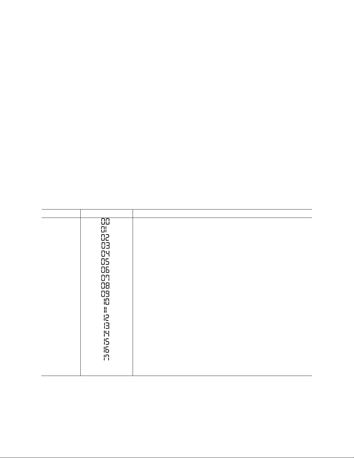
3. A brief description of the work mode:
Number
LCD Display
Description of Work Mode
0
Dusk-to-Dawn, light id on all night
1
Light turns on 1 hour after sundown
2
Light turns on 2 hour after sundown
3
Light turns on 3 hour after sundown
4
Light turns on 4 hour after sundown
5
Light turns on 5 hour after sundown
6
Light turns on 6 hour after sundown
7
Light turns on 7 hour after sundown
8
Light turns on 8 hour after sundown
9
Light turns on 9 hour after sundown
10
Light turns on 10 hour after sundown
11
Light turns on 11 hour after sundown
12
Light turns on 12 hour after sundown
13
Light turns on 13 hour after sundown
14
Light turns on 14 hour after sundown
15
Light turns on 15 hour after sundown
16
Turn on/off light mode
17
Test mode; lights turns on after no sunlight detected or lights
turn off after sunlight detected.
Table 2. Lighting control options
eLineTechnology.com
Page 3

Renogy Charge Controller Model No. PWM10CC
3
Led Indicator
Icon
LED Description
Solar Panel
• Green ON: Solar power is charging the battery
• Green BLIKING: The system is over voltage
Battery
• Green ON: Battery level is in the right range
• Green SLOWLY FLASHING: Battery level is full
• Yellow ON: Battery level is low
• Red ON: Load cut-off
DC Load
• Red ON: The output is on
• Red SLOWLY FLASHING: Overload
(The load amps is 1.25 times of the rated current for 60 seconds or
the load amps is 1.5 times the rated current for 5 seconds)
• Red BLINKING: Load is short-circuit
Table 3. LED indicators
Note: The output will shut off once there is an overload or short circuit. Disconnect all of
the equipment and then wait a few seconds before reconnecting everything. Press the
SET button and the controller will resume working after approximately 10 seconds, or in
some instances, it may take a few moments longer.
Troubleshooting
What do I do when…
1. Charging LED indicator turns off during the daytime
a. The green LED should be ON during the daytime.
b. Check to make sure the correct battery is being used.
c. Check all wiring connections to make sure they are in their designated
locations and make sure that there are no loose connections.
d. Measure the PV array open-circuit voltage and confirm it is within its
normal limits.
e. Measure the PV voltage and the battery voltage at the controller terminals.
If the voltage at the terminals is within proper specifications, the PV array
is charging the battery properly. If the PV voltage is within specifications to
the open circuit voltage rating of the panels, but the battery voltage is low,
the charge controller may not be charging the battery and it may be
damaged.
eLineTechnology.com
Page 4

Renogy Charge Controller Model No. PWM10CC
4
2. Charging LED indicator is blinking
a. Check the operating conditions to confirm that the voltage is higher than
the specifications. Consider the temperature compensation of the charge
controller’s PWM set point. For example, at 0°C the charge controller will
regulate at about 15 volts.
b. Check all wire connections in the system to ensure they are in the correct
location. Check for loose wires.
3. Red load LED indicator is blinking or flashing (load not operating properly)
a. Check the load to make sure it is on and make sure the fuses are not
blown.
b. Check connections to the load, other controllers, and battery. Make sure
the voltage drops in the system wires are not exceeded.
c. If the LED indicator is blinking and there is no output, check the load for
short-circuit. In case of short-circuit, disconnect the load and press the
SET button, and wait for approximately 30 seconds for the charge
controller to resume working again.
d. If the LED indicator is still flashing and there is no output, check the load
to make sure the load is not over the rated power. Reduce the load and
press the SET button. Then wait for approximately 30 seconds for the
charge controller to resume working again.
Inspection and Maintenance
It is highly recommended that each user inspect the charge controller at least once per
year to ensure longevity and optimal performance. Please follow this procedure:
1. Confirm that the correct battery type has been used.
2. Confirm that the current levels of the solar array and load do not exceed the
controller ratings.
3. Inspect for loose, broken, or burnt wire connections and replace them if needed.
Make sure all terminals are tightened.
4. Press the SET button until number 16 is displayed to verify the lights are working
properly.
5. Inspect for dirt, insects, and corrosion on the charge controller.
6. Check to make sure there is still enough space around the charge controller for
maximum airflow.
7. Check to make sure the charge controller functions and LED indicators are
working properly.
8. Make sure the PV array is clean and remove any debris.
9. Make sure all of the railings and PV bolts are tightened.
eLineTechnology.com
 Loading...