

Page 1

NETWORK CAMERA GUIDE
eLineTechnology
Install
Browse
Use
01.BSM.12.0092401
Product Made in China under ISO9001 & ISO1400 standards
Manual Printed in China v1.0
Network Camera setup and installation guide. Browser setup with settings explained.
Page 2
CAUTION
RISK OF ELECTRIC SHOCK
CAUTION: TO REDUCE THE RISK OF ELECTRI C SHOCK DO
NOT
REFER SERVICING TO QUALIFIED SERVICE
PERSONNEL.
eLineTechnology
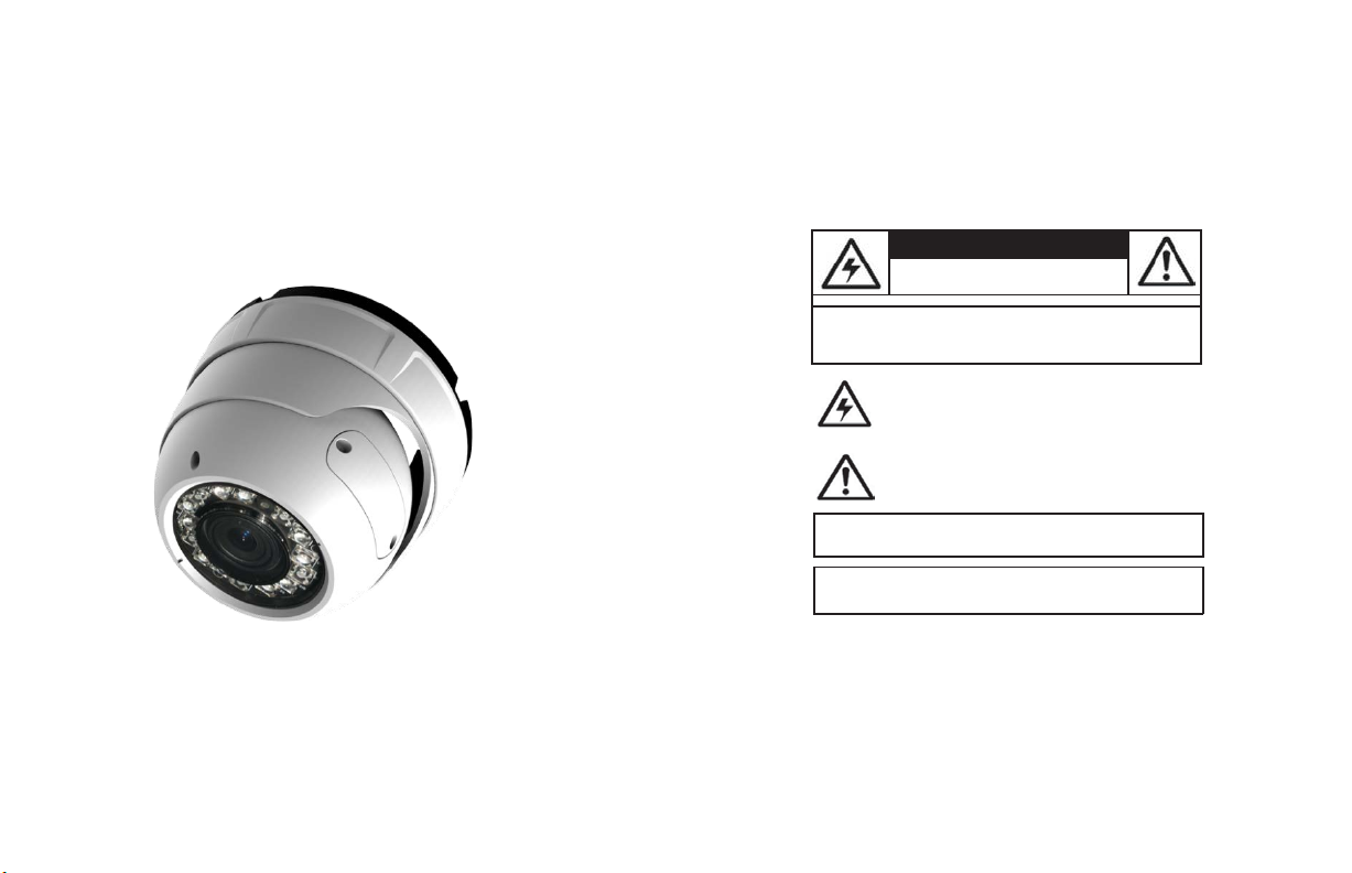
Eyeball Vandal Dome IP
Camera
DO NOT
OPEN
Instruction
English Version 1.0
Manual
REMOVE COVER.NO USER SERVICABLE PART S
The
lightning flash with arrowhead symbol, within an
equilateral triang le, is intended to alert the user to the
presenceof un-insulated "dangerous voltage" within the
product’s enclosure that
constitute a risk of electric shock.
The
exclamation point within an equilateral triangle is
intended to alert the user to the presence of important
operating and maintenance (servicing) instructions in the
accompanying
WARNING: TO PREVENT FIRE OR SHOCK HAZARD, DO
EXPOSE THIS UNIT TO RAIN OR
CAUTION: TO PREVENT ELECTRIC SHOCK, MATCH WIDE BLADE
OF THE PLUG TO THE WIDE SLO T AND FULLY
literature
may be
the appliance.
MOISTURE.
INSIDE.
of sufficient magnitude to
NOT
INSERT.
Page 3

eLineTechnology
Important
In addition to the careful attent ion
video
your
your responsibility too. This sheet lists impo rtant information that will help to assure your
enjoyment and proper use of the
carefully before operating and using your
Installation
1.
Read and Follow Instructions-All the safety and
operating instructions should be
video
ins
tr
2.
Retain Instructions-The
instructions should be retained for future
3.
Heed Warnin gs-Comply with all warnings on the
video
Polarization-Do not defeat the
4.
safety purpose of the polarized
grounding-type plug.
A polarized plug has two blades
with one wider t han the
A grounding typepl ug hastwo
blades
The wideblade or the t hird prong
are provided for
If the providedpl ug doesnot fit into
consult an electrician for replacement of th e
obsolete outlet.
PowerSources-This
5.
operatedonly from the type ofpower
indicated on the marking label. If
the type of power supply toyour
your
products intended to operatefrom batter
other s ources,
6.
Overloading-Do not overload wall outletsof
extension cordsas this can
or electric shock.
cords,
insul ation, and broken plugs are
may
examine the cord,
damage or deteriorated insulation,
by yourservicete
7.
Power Cord Protection-Power supply cordsshould
be routed so that theyare not
or pinc hedby item s placed upon or against them,
paying
conveniencereceptacles,
exit from the
Safeguards
devoted
product, safety is a major factor in the design of
product is operated.Followalloper
uctions.
product and inthe operating ins
and
video
fray
ed powercords,
result
particular attention to cords at plugs,
safety and operating
or
other.
a third ground ing prong.
yoursafety.
video
product should be
dealer orlocal
power
refer
to the operating ins
result
Overloaded AC
damagedorcrackedwire
in a shockorfire hazard.Periodically
and if its
appearance
chnician.
likelyto be walked on
and the point where they
videoproduct.
to quality standards in the manufacturing process of
video
product and
video
product.
r
ead before
the
ating
refer
ence.
tru
ctions
.
youroutlet,
sour
ce
you
are not sure of
loca
tion,consult
company.
For video
y power,
or
tru
ctions
.
in the r isk of
fire
outlets, extension
dangerous.
They
indicat
es
haveitreplac
ed
every
instrument.
However,
accessory
equipment. Please read them
8.
Ventilation-Slots and openingsin the caseare
provided
for
ventilation to ensure reliable operat
video
product and to protect itfrom
of the
These openings
overheating.
covered. The
openings should never be blocked by
video
placing the
other similar surface. T his
neverbe placed near or over a radiator or heat
This video
register.
built-in installation such as a
l
ess
proper ventilation is provided or the video
un
product manufacturer’s instructions
fo
llow
ed.
9.
Attachments-Do not usea ttachments
r
ecommendedbythe
cause
they may
10.
Camera ExtensionCa bles–Check
your extension
your
localauthority regulationsprior to inst
11. Water
and Moisture-Do not useth is
near water. For example, neara bath tub, wash
bowl, kitchen si nk or laundry tub, in aw
basement, near aswimming pool and the
Caution: Maintain elec trical safety.
operated
equipm ent or accessories connected to
this uni t should bear the ULlisting mark of C SA
certification mark on the
not be modified s oas to defeat the safety
This
will
help
electr ical shoc kor f ire. If in doubt, contact qualified
service personnel.
12.
A
ccessories-Do not placethis
video
equipm ent on anunstabl
cart, stand, tripod, or table. T he
video
equipment may fall, causing
damage
serious
product. Use this
only with a cart, stand,
bracket, or tablerecommendedbythe
manufacturer or sold wit h the
mounting of the p roduct should
manufacturer’s instructions and use amount ing
accessoryreco
must not be blocked
equipm ent on abed, sofa, rug,
video
product should
product should notbeplaced in a
bookcaseorrack
have
video
product manufacturer as
a h
azard.
cable(s)
avoid any
to the video
videoproduct
mmended by the manufacturer.
the rating of
to verify compliance with
videoproduct
Powerline
accessory
itself
potential hazard
e
tripod,
video
product. Any
follow the
safety is
been
unl
ess
allation
e
t
lik
e.
and shou
fea
tures.
from
Service
13.
Servicing-Do not attempt to servicethis video
equipment yourself asopening
may
expose
you to dangerousvoltage or other
Referall servicingt o qualified service
hazards.
personne
l.
Conditions Requiring Service-Unplug this video
14.
product from the
qual
ifi ed servicepersonnel under thefollowing
cond
itions:
•
When
ion
or
or
.
ld
the power supply cord or plug is damaged.
•
If liquid has
been
the
videoproduct.
•
If the
video
product has been
water
.
•
If the
video
product
foll
owingthe oper ating instructions. Adj ust only
those controls that are covered byth e operatin
instructions. Improper adjustment of othercontr
result
in
damage
may
work by aqual
extensive
the
video
product to its normal operation
•
If the
video
product
has been damaged.
•
When
the
video
in performance. This i ndicates an eed
15.
Replacement
Parts-When
required,
have
the serv icetechnician ver ify that the
replacements used
characteristics as the original parts. Use of
replacements specified by the
manufacturer can prevent fire,
other hazards.
16.
Safety Check-Upon completion of
repairs to this
video
technici an to perform safety checks
by the manufacturer to determ ine tha t the video
product is in safe operating
17. Wall or
Ceiling Mounting -The cameras provided
should be mounted to a w
instructed in this guide,using the p rovided
br
acke
mounting
18. Heat
-
The productshould be situated
heat sources suchas radiators, heat
stoves,
or other products (including amplifiers) that
produce
heat.
orremoving covers
walloutlet and
product exhibits a distinct change
ts.
refer
spilled or objects
has beendropped
have
product, ask the service
havefallen
exposed torain or
does
not operate normally by
and
will
oftenre
ified techniciantorestor
replacemen t partsare
the same safety
videoproduct
elec
tric
any
r
eco
co
ndition.
allor ceilingonly
regis
servicing to
quir
or theca binet
for
shockor
service
mme
awayfrom
.
service.
as
ter
e
s,
or
nded
Use
19.
Cleaning-Unplug the
outletbeforecleaning.Donot useli
aerosolcleaners. Usea damp cloth
Product and
Cart
20.
combinat ion should bemoved withcare.
stops,
causet he
verturn.
o
Object and Liquid Ent ry-Never push objects of any
21.
kind into this
they mayto uch dangerousvol tagepoints
int
o
“short-out”
elec
video produc
22.
Lightning
product during a lightnin g storm, or when it is
unattended andunused
g
unplug it
antenna
ols
to the
su
r
e
Combination-Video
excessive
force, and
video
product and cart combinationto
video
product through openingsa s
parts that could
tric
shock. Never
t.
- For
added
from
the wall outlet anddi sconnect the
orcablesystem. This
video
product due tolightning and power line
ges.
video
product from the
quidcleanersor
forclea
uneven
surfaces may
result
in a fire
spill
liquid of any kind on the
protection
for
this video
forlong
periods of time,
willpreventdamage
andca
Quick
or
ning.
or
wall
rt
left
Precautions
Page 4
eLineTechnology
General
1. All warnings and instructions in this manual should befollowed.
2.
3.
4. During lightning storms, or when the unit is not used for a
FCC CLASS A
Precautions
Remove
the plug from the outlet before cleaning.Donot use liquid aerosol detergents.
dampened
enough
cloth for cleaning.
space
around the unit for ventilation. Slots and openingsin the stor
l
ong
time, disconne ct the power
sur
water
Keep
should not beblocked.
supply, antenna, and cables to protect the un it from ele ctrical
NOTICE
ge.
NOTE
This equi pment has been tested and found to comply with the limits for a Class A digital device pursuant to
Part 15 of the FCC Rules. Th ese limits are designed to provide r easonable protectio n against
interf erence wh en the equipmen t is operat ed in a commercial environm ent. This equi pment gener ates, uses,
and can radiate radi o frequency energy and, if not installed and used in accordance wit h the manu
instruction manual, may
in a residentia
interf erence at your own expen se.
cause
lareais likely to cause harmful interferen ce, in which case you wil l be req uired to correctthe
harmful i nterference with radio communications.
Operation
of thi sequipmen t
This
equipment
has been
certified
and
LVD.
Therefore, it is
cause
interference with othe r applianceus age.
However,
usage which may result in da mage to the unit, electrical shock and fire hazard injury.
In order to improve the feature functions
to
change
designatedtoprovide
it is imperative that the user follows the guidelines in this manual to
without notice f rom time to time.
found to comply with the limits regulated
reasonable protection against interference
and
quality of this product, the specifications are
by FCC, EMC,
avoid
Use
age
cabinet
ha
rmful
facturer’
and
will not
improper
subje
Features
a
s
and
ct
•
HD
CMOS
•
720p or 1080p models with
•
Triple-streaming
•
Future proof
•
Compatible with popular third party
•
Power-over-Ethernet
•
Backup options: micro SDcard
•
Mobile Apps: iPhone®, iPad®, Android™
•
Supports two-way audio
•
Simple insta
•
2.8-12mm vari-focalle
•
30 ft. (9m) IR Night
•
IP66
•
Multi-browser support:
•
3-axis gimbal
Progressive Scan
(H.264/MJPEG)
ONVIF 2.1
compliance
(PoE)
llation and adjustment
ns
Vision,TrueDay/Night (TDN)
Weatherproof and IK5
IE,
for versatile mounting
real-time
operation,
(25/30
fps)
(1.02
backwardsco
VMS
softwar
14Watt max/12V
, FTP, NAS,loca
Vandal
Resistant
Firefox, Safari, Chrome
mpatibl
e)
e*
operation
l
*
Check Onvif c ompliance on for y our software.
Page 5

eLineTechnology
TABLE OF
1.
Getting
Started . . . . . . . . . . . . . . . . . . . . . . . . . . . . . . .. . 1
CONTENTS
1.1 Default Camera Username, Password, and Ports . . . . . . . . . ..1
1.2 Camera Interior Overv iew . . . . . . . . . . . . . . . . . . . . . . . . . . . . . .
1.2.1
Functions of Status LED’s . . . . . . . .. . . . . . . . . . . . . . . . . . . . . . . .. . . . . . . . . . .. . . . .
1.3
ONVIF
Compatibility and Included Software Overview . . . . . . ..3
1.3.2
1.3.3 CD Conten ts
2.
Connection
Camera
3.
Finding
4.
NVMS . . . . . . . . . . . . . . .. . . . . . . .. . . . . . . . .. . . . . . . . . .. . . . . .. . . . . .. . . . . . . .
. . . . . . . . . . . . . . . .. . . . . .. . . . . . . . . . . . .. . . . . .. . . . . .. . . . . . . . . . .
. . . . . . . . . . . . . . . . . . . . . . . . . . . . . . . . . . . . . 4
Installation . . . . . . . . . . . . . . . . . . . . . . . . . . . . . 5
the
Camera’sIPAddress
. . . . . . . . . . . . . . . . . . 8
4.1 Finding the Camera’s IP Address Using NVMS . . . . . . . . . . . . ..9
4.2 Finding the Camera’s IP Address using
UPnP
4.3 Finding the Camera’s IP Address using Bonjour® in Mac OS®
4.4 Finding the CameraIP using the BNC Test Cable . . . . . . . . . . .
5.
Configuring Remote
5.1
Connecting
6.
Web Configuration
to a
Connection
DDNS
address using NVMS . . . . . . . . . . . . . ..15
. . . . . . . . . . . . . . . . . . 12
. . . . . . . . . . . . . . . . . . . . . . . . . . . . . 17
6.1 Supported Browsers . . . . . . . . . . . . . . . . . . . . . . . . . . . . . . . . ..17
6.2 Chrome, Firefox, and Safari Setup . . . . . . . . . . . . . . . . . . . . . .
6.3 Internet Explorer® Setup . . . . . . . . . . . . . . . . . . . . . . . . . . . . .
6.4
Web
Interface/Live
6.4.1
Live
Video
Configuring Camera Settings . . . . .. . . . . . . . . . . . . . . . . . . . . .. . . . . . . .. . . . . . . . .
6.4.2
6.5
Device
Info . . . . . . . . . . . . . . . . . . . . . . . . . . . . . . . . . . . . . . . . . ..23
Video Overview
Menu . . . . . . . . . . . . . . . . . . . . . . . . . . . . . . . . . . . . . . . . . .. . . . . . . . . . . . .
. . . . . . . . . . . . . . . . . . . . . ..21
6.6 Stream Configuration . . . . . . . . . . . . . . . . . . . . . . . . . . . . . . . .
6.7
Device
Configuration . . . . . . . . . . . . . . . . . . . . . . . . . . . . . . . . ..25
6.7.1
Local Network . . . . . . . . . . . .. . . . . . . .. . . . . . . . . . . . . . . . . . . . . .. . . . . . . . . . .. . . .
6.7.2 Device
6.7.3
6.7.4
6.7.5
6.7.6
Port . . . . . . . . . . . . . . . . . . .. . . . . . . . . . . . . . . . . . . . . .. . . . . . . .. . . . . . . . ..
Camera . . . . . . . . . . . . . . . . . . . . .. . . . . . . . . . . . . . . . .. . . . . . . . . . .. . . . . . . . . . . . .
Date & Time . . . . . . .. . . . . . . . . . . . .. . . . . . .. . . . . . . . . . . . . . . . . . . . .. . . . . . . . . .
OSD . . . . . . . . . . . . . . . . . . . . . .. . . . . . . . . . . . . . . . . . .. . . . . . . . .. . . . . . . . . . .. . . .
Microphone . . . . . . . . . . . . . . .. . . . . . . . . . . . . . . . . . . . . . . . . . . . . . .. . . . . . . . . . . . .
in Windows® 7. .
6.7.7 BNC Video
6.7.8
6.8 Alarm Configuration . . . . . . . . . . . . . . . . . . . . . . . . . . . . . . . . . .
6.8.1
6.8.2
6.9 Local Record . . . . . . . . . . . . . . . . . . . . . . . . . . . . . . . . . . . . . . . .
.
2
2
3
3
9
10
.
11
.
17
.
18
21
22
.
24
26
27
28
28
30
31
6.9.1
6.9.2
6.10
Privacy Masking . . . . . . . . . . . . . . . . . . . . . . . . . . . . . . . . . . . .
6.11
Network Service . . . . . . . . . . . . . . . . . . . . . . . . . . . . . . . . . . . .
6.11.1
6.12 Service
6.12.1 SMTP
6.13
Privilege Manager . . . . . . . . . . . . . . . . . . . . . . . . . . . . . . . . . . .
6.13.1
6.13.2
6.13.3
6.14
Protocol . . . . . . . . . . . . . . . . . . . . . . . . . . . . . . . . . . . . . . . . . . .
6.14.1
6.15 Device
6.16
Default Settings . . . . . . . . . . . . . . . . . . . . . . . . . . . . . . . . . . . .
6.17
Sensor Configuration . . . . . . . . . . . . . . . . . . . . . . . . . . . . . . . .
6.17.1
6.17.2
6.17.3 Gain
6.17.4
6.17.5
6.17.6
6.17.7 AE
6.17.8 WB
6.17.9
6.17.10
6.17.11
7.
ResettingtoFactory
8.
Dimensions
Troubleshooting
9.
Output . . . . .. . . . . . . . . . . . . . . . . . . . . .. . . . . . . .. . . . . . . . .. . . . . . . . ..32
Language . . . . . . . . . .. . . . . . . . . .. . . . . . . . . . . . . . . . . . . . .. . . . . . . . . .. . . . . . . . ..32
Disk Alarm . . . . . . .. . . . . . . . . .. . . . . . . . . . . . . . . . . . . . . . . . . . . . . . . . . . . . . . . . . ..33
Motion Alarm . . . . . . . . . . . . . . . . . . . . . . . . . . . . . . . . .. . . . . . . . . . . . . . .. . . . . . . . ..34
Record Directory . . . . . . . . . . . . . . . . . . . . . . . . . . . .. . . . . . . .. . . . . . . . .. . . . . . . . ..36
Record Policy . . . . . . . . . .. . . . . . . . . . . . . . . . . . . . . . . . . . . . . . . . . . . . . . . . . . . . . . ..41
33
36
43
DDNS . . . . . . . .. . . . . . . . . .. . . . . . .. . . . . . . . . . . . . . . . . . .. . . . . . . . .. . . . . . . . ..44
Center . . . . . . . . . . . . . . . . . . . . . . . . . . . . . . . . . . . . . .
(Email Alert Setup) . . . . . . . . . . . . . . . . . . . . . .. . . . . . . .. . . . . . .. . . . . . . . ..45
Group . . . . . . . . . . . .. . . . . . . . . . . . . . . . . . . . . . . .. . . . . . . .. . . . . . . . . . . . . . . . ...47
User . . . . . . . . .. . . . . . . .. . . . . . . . . . . . . . . . . . . .. . . . . . . .. . . . . . . . . . . .. . . . . ..48
Unlocking User Accounts . . . . . . . . . . . . . . . . . . .. . . . . . . .. . . . . . . . . . . .. . . . . . ..49
Protocol . . . . . . . . .. . . . . . . . . . . . . . . . . . . . . . . . . . . . . . . . . . .. . . . . . .. . . . . . . . ..50
Restart . . . . . . . . . . . . . . . . . . . . . . . . . . . . . . . . . . . . . .
44
45
46
50
50
51
Image Adjust . . . . . . . . . .. . . . . . . . . . . . . . . . . . . . . .. . . . . . . .. . . . . . . . . . . .. . . ..52
Shutter Control . . . . .. . . . . . . . . . . . . . . . . . . . . . . . . . . . . . .. . . . . . . . .. . . . . . . . ..52
Mode .. . . . . . . . . . .. . . . . . . . . . . . . . . .. . . . . . .. . . . . .. . . . . . . . .. . . . . . . . ..53
Day/Night Mode . . . . . . . . . . . . . . . . . . . .. . . . . . . . . . . . . . . . . .. . . . . . .. . . . . . . . ..53
Auto Iris . . . . . .. . . . . . . . . . . . .. . . . . . . . . .. . . . . . .. . . . . . . .. . . . . . . . . . . .. . . ..54
Gamma . . . . . . . . . . . . . . . . . . . . .. . . . . . . . . . . . . . . . . . . . .. . . . . . . . . . . . . . .. . . ..54
Meter
Mode
. . . .. . . . . . . .. . . . . . . . . .. . . . . . .. . . . . . . .. . . . . . . . . . . . . . . . . ..55
Setting . . . . . . . . . . . .. . . . . . . . . . . . . . . . . . . . . .. . . . . . . .. . . . . . .. . . . . . . . ..55
WDR . . . . . . . . . . . . . . . . . .. . . . . . . . . .. . . . . . . . . . . . . . . . . . . . . . . . . .. . . . . . . . ..56
Mirror . . . . . . . . . . . . .. . . . . . . . . . . . . .. . . . . . . . . . . . . . . .. . . . . . . . .. . . . . . . . ..57
Noise Filter . . . .. . . . . . . .. . . . . . . . . . . . . . . . . . . . . .. . . . . . . . . . . . . . . . . . . . . . ..57
51
Defaults . . . . . . . . . . . . . . . . . . . 58
. . . . . . . . . . . . . . . . . . . . . . . . . . . . . . . . . . 59
. . . . . . . . . . . . . . . . . . . . . . . . . . . . . . 60
Page 6
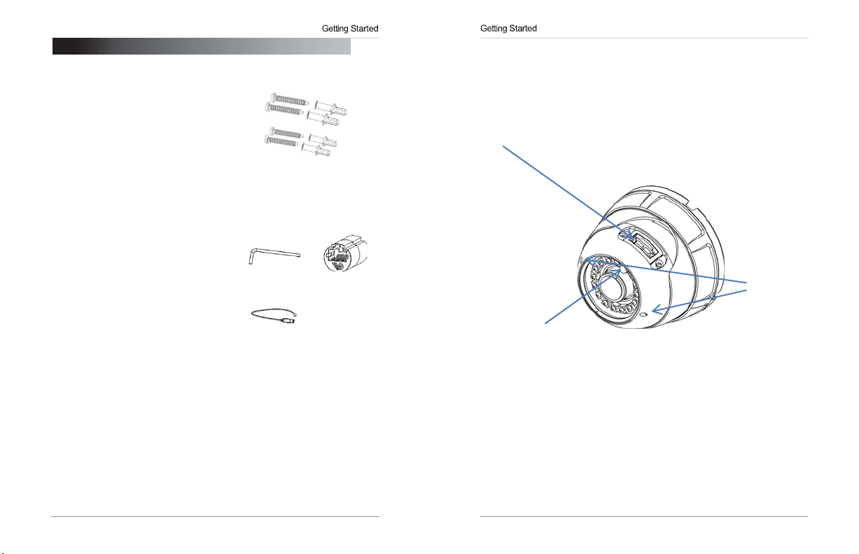
CdS Light sensor
Lens Zoom
& focus adjust
eLineTechnology
1.
GETTING
The
system comes with the following
components:
•
1 x Camera
•
1 x Mounting Screw
•
1 x Allen Key
•
1 x
•
1 x
•
1 x Mounting Template
•
1 x Quick Start Guide
•
1 x Instruction Manual
•
1 x Software/Documentation CD
1.1
Username: admin
Password: admin
Ports: 80
IP Address:
address)
NOTE:
recommendedto
IP addresschanging in the
Local Network” on page 26.
1 2
STARTED
Kit
RJ45
Coupler
BNC
Test Cable
Default Camera Username, Password, and
(HTTP),
30001
(Control/Streaming), 8080
DHCP Enabled by Default
Once
you
have
completed the basic setup of the camera, it is
configureastaticIPaddress. This
event
of a power failure. For details,
Mounting Screw
•4x
mounting screws
(PA4
30mm)
•
4 x drywall anchors
Allen Key
BNC Test
Cable
(RTMP),
(Router will automatically assign IP
willprev
Kit:
RJ45
Coupler
Ports
554 (RTSP)
ent theca
see
mer
“6.7.1
1.2
Camera
Interior Overview
Access panel. With Micro sd Card slot*. Status LED, camera reset & service
video
*microSD card slot (max. 64GB supported; SanDisk™/Kingston™ brand
memory cards
1.2.1 Functions of Status
•
a
POWER (Top):
•
NET (Middle):
LED’s
Glows
green when camera is
Flashes red to indicate network activity. recommended)
connected
to power.
Page 7
eLineTechnology
1.3
ONVIF Compatibility and Included Software
This camera is
popular
more information on
NOTE:
cameras is available via Safari® browser only.
1.3.1
•
NVMS
cameras.
•
NVMS
card recordings and camera setup over a local network.
•
NVMS
ONVIF v2.1
VMS’s and NVR’s*,
Provided software is
compliant. It is designed for interoperability
with backwards compatibility to
ONVIF,
visit www
.onvif
PC
compatible only; Mac
NVMS
is a
client-only solution
NVMS
is a free software provided on the CD.
supports all the features of the camera. It
manual is provided on the
that
CD.
.or
supports up
g
to 36IP
can access
Overview
ONVIF v.1.02.
OS® access
microSD/
with
For
to the
SD
1.3.2 CD Tools
•
CD contents Folders
IP Search ; Search find IP Cameras and set IP address and gateway
NTP Service Tool ; Time Sync Application: IP devices match one PC system time.
FTPUpdater ; Firmware Update tool
IP Support Help Files ; Website support help documents for common problems.
RTSP Tool ; provides RTSP string command f. e.g VLC or Quick-time use
SD Driver ; Ext2 driver for Windows XP to read sd Memory card on PC
Onvif_Help ; documents on Onvif specifications
Open the NTP service ; Windows XP only enables NTP time to be enabled.
Adobe Flash Player ; Flash Video player for Windows IE plugin and Apple Mac OS
Adobe AcrobatReader ; Windows and Max OS Acrobat Reader v10
Files:
IP_series_bitrate_calculator.htm ; Simple storage calculator for IP devices
NVMS_Install.exe ; NVR Software installation for PC
NVMS_Manual_1.7.pdf ; Guide to use the NVMS Software
SNMedia_Player.exe ; File Player for recorded files / backup files from devices /
NVMS.
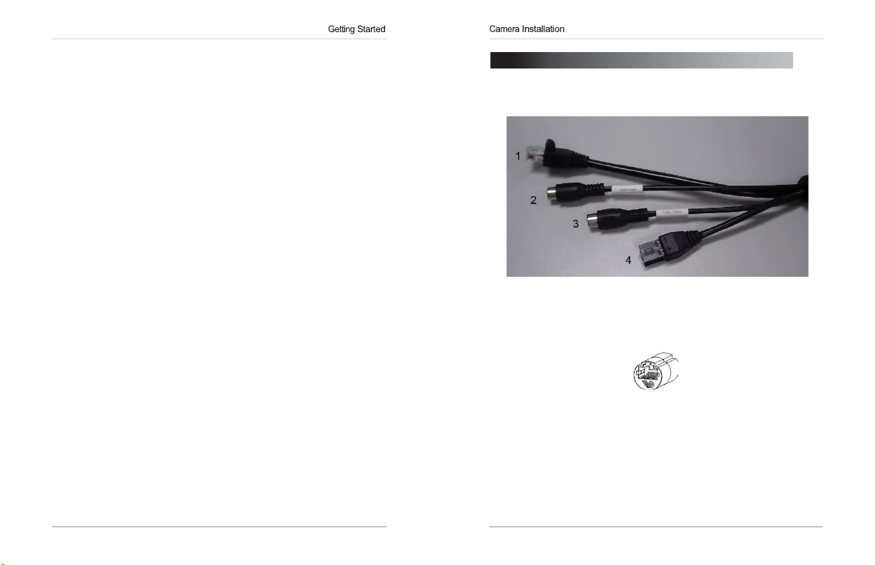
2. CONNECTION
The
camera has the following termination cables:
1.
RJ45
Network
RJ45
Ethernet cable
Use
the included
Interface:
12V DC
using
supported (class 3
NOTE:
Ethernet cable.
2.
Audio Input (RCA):
audio.
Audio Output (RCA):
3.
intercom/2-way audio.
DC12V (1A):
4.
polarity (+/-) marked on the power connector when connecting to power.
•
Minimum Power Requirement:
Connect
to a
router
(Cat5e
PoE
switchre
Connect
Connect
power input terminal. Make sure tofollow corr
or better).
quir
RJ45
coupler to connect to male end of RJ45
RJ45
Coupl
to a self-powered microphone
to an amplifier or self-powered speakerfo
450mA/5.4W.
or switch on your network
100Mhz
ed).
er
connection. PoE
for listen-in
r
ect
3 4
Page 8
Connection
eLineTechnology
3.
CAMERA
1.
Use
remove
camera will simple be removed
away
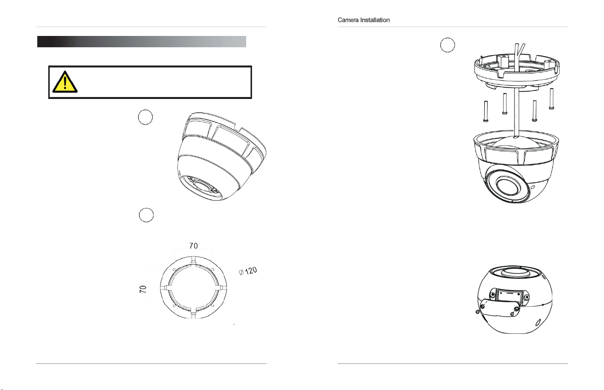
2.
Use
template or the camera base
plate to mark holes
mounting
5 6
INSTALLATION
Make
sure to follow the correct polarity if connecting
the camera to
power connector.
the included allen
make lose the top 1
from the
the included mounting
screws.
base part.
for
keyto
the four
DC
power. Polarity is marked on the
Mounting Screw Hole
2
Mounting Screw Hole
3. Mount the camera to the
surface using the included
mounting screws (4x).
4.
Now refit camera into base
Adjust position as needed
5.
(Optional)
card into the camera. To
enable recording, you mus
format
configure microSD
recording. For details, see
“6.9.1 Record Directory” on
page
sdCard access is behind
panel on camera
NOTE:
microSD cards up to a
maximum size of 64GB.
SanDisk™orKingston™
microSD cards are
recommended.
Insert a microSD
the microSD card and
36.
The
camera supports
brand
3
t
Page 9
Finding the Address
eLineTechnology
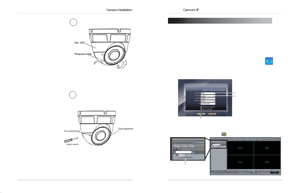
6. If you need to adjust the
viewing angle,
screws on the sides of the
ball camera and adjust the
ball camera.
cover
loosen
.
Tighten the
when finished.
7. Adjust camera zoom focus
Use service video cable
for BNC output.
Adjust the focus zoom
With small flat blade
the
6
4.
FINDING THE CAMERA’S
Use
the steps below to find the camera’s IP address and connect to the
camera over the local area network
Windows® 7, or Bonjour® in Mac OS®.
4.1
Finding
1. Install
Desktop.
2. Under User Name and
(
admin)and password(admin).Click Login.
the
Camera’sIPAddress Using
NVMS
from the
Thelogin screen
CD. Now
Password,enter the default
appears.
(LAN)
Doubl
e-click
IP ADDRESS
using
NVMS, UPnP
the
NVMS
NVMS
on
NVMS
icon
user name
(
) on the
7
Enter Admin
Enter Admin
NVMS
3.
Detected camera IP addresses on the LAN appear in the
the
left
Click Login
opens and scans the localnetwork
side of the screen with a icon.
for
connectedca
mer
Device
as.
List on
Found
camera
IP address
7 8
Page 10
Finding the Address
Finding the Address
eLineTechnology
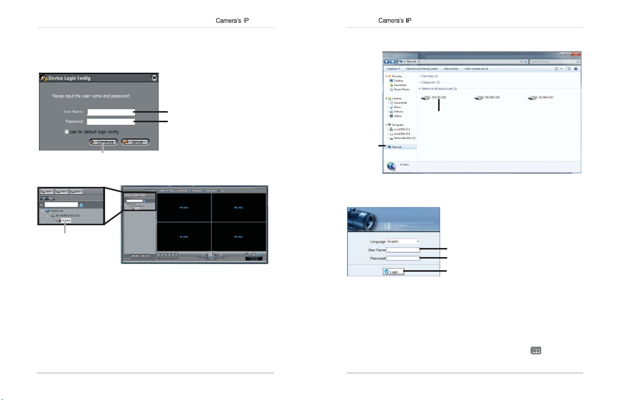
4. Click on a camera IP address in
5. Under
User Name,enter the user name
Password,enter the password
Under
Click Continue.
Device
List tolo
gin.
for
the camera (default: admin).
for
the camera (default: admin).
Enter Camera User Name
(default: admin)
Enter Camera Password
(default: admin)
Click Continue to login
6.
The
camera appears under the camera IP address. Click and drag the
camera to the display grid to open
it.
Click and drag the
camera to the display
grid to open
it
NOTE:
manual on the CD.
4.2
Finding
Windows®
NOTE:
and
computer mustbeon
by
default,
manual
For detailed instructions on using
the
Camera’sIPAddress using UPnP
7
To use
this method, your
and canbeenabled/disabledusing
for details).
the
same
router
network.
NVMS,
see the NVMS
must support
UPnP
NVMS (check
UPnP and
is enabledin
in
theca
mer
theca
mer
the NVMS
1. Click
under Network
Start>Computer>Network.The
Infrastructur
e.
camera’s IP address appears
Double-click to open
the camera
Network
2. Double-click the camera to open it in your default browser.
3. Under User Name and
admin)and Password (default:
(default:
4.3
Finding
Mac
OS®
NOTE:
a
a
network. Bonjour® is enabledby default, and can be enabled/disabl
using
1.
Open
the
To use
this method, the camera
NVMS
(check the
Safari® browser and click the Bookmarks button ( ).
Password,enter the camera’s User Name
Enter Camera User Name (default: admin)
Enter Camera Password (default: admin)
Click Login
admin)and click
Camera’sIPAddress using
and
computer must
NVMS
manual
for details).
Login
.
Bonjour®in
be on
the same
ed
9 10
Page 11
Finding the Address
Configuring Connection
80 80
Control
30001
30001
100
eLineTechnology
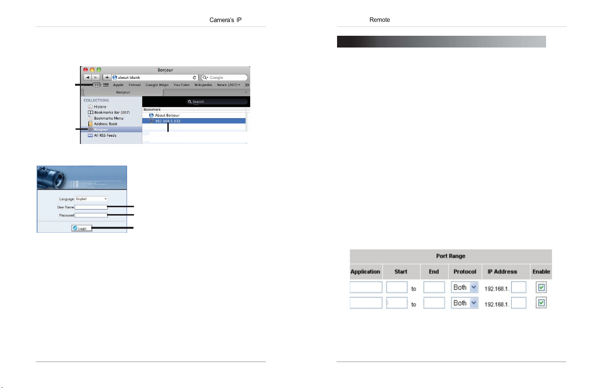
2. Click
Bonjour
. The
list.
3. Double-click the camera to open it in
camera’s IP address appears in the Bonjour Devices
Bookmarks
button
Bonjour
4. Under User Name and
(default:
admin)and Password (default:
Password,enter the camera’s User
Enter Camera User Name (default: admin)
Enter Camera Password (default: admin)
Click Login
4.4
Finding
When
on the test monitor.
test cable.
NOTE:
cannot obtain an IP address from the
connections and
the
the
BNC
test
The
default IP address of
CameraIPusing
cableisconnected
The
camera must
routerco
nfigur
Saf
ari®.
Double-click the camera’s IP address
admin)and click
the
to the camera, the
be connected
192.168.0.120
router.
ation.
BNC Test
to power to use the BNC
is shown if the ca
Check
Name
Login
.
Cable
IP address
the Ethernet/power
is shown
mer
a
5. CONFIGURING REMOTE
Follow the steps below to configure your camera for connections over the
Internet using a web browser,
Step
1 of6:
Locate
the
•
See
“4. Finding the Camera’s IP Address” on
Step
2 of6: Port
You
need to enable port forwarding for the following ports on your router to
the camera’s local IP address:
•
HTTP
•
Control Port (default: 30001)
NOTE:
access, you
use the same port number
NOTE:
your installation has specialre
There are two methods for port forwarding:
•
You
for details. An example of a port forwarding screen is shown below.
Forward your
Port (default: 80)
If you are configuring multiple IP cameras
must
change
Port forwarding the
can
manually port forward your router.
NVMS,
camera’s local
router:
the ports
.
RTSP
quir
or other
IP address:
for
and
ements.
CONNECTION
VMS
software.
page 8
.
for
camera.
ports is not
individualre
Two
cameras cannot
necessary
each
RTMP
See yourrouter’s user manual
HTTP
100
mot
unless
e
11 12
Page 12

Configuring Connection
Configuring Connection
eLineTechnology
Step
3 of6:
Locate your camera’s MAC
Open
a web browser and enter the camera’s IP address in the address
1.
bar in the followingfo
http://
http://192.168.0.120:80
2. Under User Name and
(default:
3. Click
admin)and Password (default:
Device Info
rmat:
IP
address
Password,enter the camera’s User Name
and write down the
address:
Colon
HTTP
MAC
Step
4 of6:
Register
Register for one of the DDNS
with your IP camera. A DDNS account allows
address
that points back to your local network.
set up your free
NOTE:Your router
NOTE:
You
the same LAN.
for DDNS:
services which are currently supported for use
DDNS
account.
must support
may use the same
UPnP
DDNS
to enable DDNS.
account
port number
admin)and click
Address.
MAC
you
to set up
The
following outlines how to
for
multiple IP cameras on
Login
Address
.
a web
site
Step
5 of6:
1. Ent
2.
3. Configure the
•
•
•
•
4. Click
Step
1. Enter the camera’s
2. Under User Name and
Once
connect to the IP camera from a remote location using a web browser,
NVMS
Servic
Network
Check
Provider:
Domain Name:
confirmation email you received after you created your
(e.g.
User Name:
Password:
OK
6 of6:
format
http://
http://
(default:
you
.
e>DDNS
Enable
DDNS.
foll
Select the ddns service you use..
mycamera.dyndns.org
Enter the
Enter the account name
to
save
Connect
:
mycamera.dyndns.org:80
admin)and Password (default:
have
logged into your s ystem using your
Enable DDNS on
er the camera’s IP address in your web browser. Log in and then
the camera:
.
owing:
Enter the
settings.
Domain
Name you received from the
).
User
Name
.
Password
to the
camera’s DDNS
DDNS
address in your web browser in the following
DDNS
address
Password,enter the camera’s User Name
address:
HTTP
admin)and click
DDNS
DDNS
Colon
port number
Login
address, you can
click
account
.
13 14
Page 13

Configuring Connection
Configuring Connection
eLineTechnology
5.1
Connecting
NOTE:
method.
Open NVMS
1.
2. Click
Manager
Enter the
camera’s
DDNS
address
3. Under
For example, enter
4. Under
5.
(Optional)
Add
6. Click
7. Click
Savetosave changes.
to a
DDNS address using
Complete all the steps
and click
. The Device Maintenance
Device
IP, enter the
Control
mycamera
Port, enter the camera’s control port (default: 30001).
Under
Device Name,enter a name
to add the camera to the
above
before performing the following
Device
Manager>Video
Click Add Click Save
Domain
Click OK.
window opens.
Name from the confirmation email.
.dyndns,org
Device
Lis
.
for
t.
Device
the ca
NVMS
Manager.
mer
a.
Control
Port
8.
Close Device Maintenance
Video
screen.
The
newly
and
Device Manager,
added
camera will appear in
and
Found
camera
NOTE:
A icon is shown
not affect your ability to connect to the camerare
9. Click on the camera in
admin)and
Password
for
all cameras outside of the LAN. This does
Device
List tolo
(default:
gin. Enter the
admin)and then click Continue.
motely.
Enter Camera User Name (default: admin)
Click Continue
10.Click and drag the camera to a display grid screen to open
Click and drag the
camera to the display
grid to open
it
NOTE:
For detailed instructions on using
manual on the CD.
Enter Camera Password (default: admin)
NVMS,
see the NVMS
return
to the
Device
Lis
User Name
it.
t.
(def
Liv
e
ault:
15 16
Page 14

Configuration
Configuration
eLineTechnology
6.
WEB
The
camera includes a built-in web interface that can be
web browser.
6.1
•
Google
Player)
•
Microsoft Internet Explorer®
6.2
1.
Connect
address.
Open
2.
in the
NOTE:
setup and port forwarding required; see “5. Configuring Remote
Connection” on
3. Under User Name and
(default:
CONFIGURATION
Supported
Chrome, Firefox, and
your browser and enter the camera’s IP address in the address bar
foll
You
Browsers
Chrome, Mozilla Firefox, and Apple Safari®
7.0
or later, 32-bit version
Safari Setup
the camera to yourlocalnetwork and find the camera’s IP
See
“4. Finding the Camera’s IP Address” on
owingfo
rmat:
http://
http://192.168.0.120:80
Camera IP address
can also connect to the camera using a
page12for
admin)and Password (default:
details).
Password,enter the camera’s User
Colon
HTTP
port number
DDNS
admin)and click Login.
Enter Camera User Name (default: admin)
Enter Camera Password (default: admin)
Click Login
accessed
(via Adobe
(via
ActiveX®)
page
9.
address (DDNS
Name
using a
Flash
4.
The
main screen
view and configure the
NOTE:Ifyou
has the latestvers
www.adobe.com/ to download the latest version). After installing Flash
Player, restart your browser and reconnect to the camera.
6.3 Internet Explorer® Setup
Step
1 of2:
Open
Internet Explorer and open the Security tab.
1.
•
Internet Explorer 8: Click
Security
•
Internet
tab.
2. Click
Custom
do not
Change
tab.
Explorer 9:
Level.
for
the camera web interface
camer
a.
see video
ion of
Internet
from the camera, make sure yourco
Adobe
Flash Player installed
Explorer security settings
Tools>Internet
Click>Internet
opens.
Options
Options
From here youcan
(visit
http://
for ActiveX®:
and select the
and
select the Security
Click Custom level
mputer
17 18
Page 15

Configuration
Configuration
eLineTechnology
Download unsigned ActiveX controls,click Prompt
3. Under
(recommended) or Enable.
Select Enable or Prompt under
Download
unsigned
ActiveX
Click
4. ClickOK.
Step
1.
2. Enter the camera’s IP address in the address bar in the
Click OKagain to
2 of2:
Log into
Connect
address.
camera:
the camera to yourlocalnetwork and find the camera’s
See
“4. Finding the Camera’s IP Address” on
http://
http://192.168.0.120:80
IP address
NOTE:
You
setup and port forwarding required; see “5. Configuring Remote
Connection” on
3. Under User Name and
(default:
can also connect to the camera using a
page12for
Password,enter the camera’s User
admin)and Password (default:
OK
save
changes.
Colon
HTTP
port number
DDNS
details).
admin)and click Login.
Enter Camera User Name (default: admin)
Enter Camera Password (default: admin)
Click Login
controls
page 9.
IP
foll
owingfo
address (DDNS
Name
rmat:
4. If your computer has Flash Player installed,
camera web interface
camera.
NOTE:
The ActiveX
Flash Player.
Then
click inside the
this computer,and follow the prompts.
To
use
plug-in
opens.
From here youcan view and configure the
may
ActiveX,
video area,
provide smoother
click the
select
the main screen
message above
Install
video
this Add-on for
performance than
the
Install
ActiveX
plug-in
NOTE:
If your computer
prompted
toselect ifyo
to thecamera:
•
Clicktoplay
(recommended):
install the plug-in, click on the
for all
•
Clicktodownload
Opens
completing the installation, restart your browser and reconnect to the
camera.
live
users on this computer,and follow the prompts.
a link to download Flash Player from
does
not
u would liketo
video
with
UsesanActiveX
ActiveX controltoreduce
the latest
versionofFlash
have
Flash Player installed,
use ActiveXor Flash
plug-in to connect to the camera. To
video
area,
and
Adobe’s
Playertoconnect
latency
select Install
Player to
play
website.
Select
ActiveX
or Flash Player
for the
video
all
you will be
this
live video:
After
window.
users
Add-on
on
19 20
Page 16

Configuration
Configuration
eLineTechnology
6.4
Web
Interface/Live
Camera
configuration
menus
TIP:
Select stream2 for better performance for remote
connections. Stream2 has a lower resolution than stream1.
The
Live
video page
requires an Active X® plug-in or
6.4.1 Live Video
You
can
right-click
appears when you log into the camera. Live video
Menu
on the live
Video
Click and drag to zoom in. Right-click and
select
Double-click inside window for
Select Stream
Overview
ZoomOut
Adobe
video
Right-click on the
open the Live
to zoomout.
Flash Player.
area to bring up the Live
Video
video
Menu
full-screen
Video
area to
Menu.
The Live Video Menu contains
•
Full
Screen:
Open
•
Sensor Config:
Configuration” on
•
ZoomIn:
•
ZoomOut:
•
Restore Panorama:
Configure the camera sensor settings.
Zoom in one level.
Zoom out one level.
the
following
the
video
in full screen. Press
page 51.
Zoom out all the way.
options:
ESC
to exit fullscreen.
See
6.4.2 Configuring Camera Settings
•
Click the optionsonthe left to configure camera settings. Setting options
are detailed in the remainder of this section.
Click to select
camera menus
TIP:
Some
sub-menu options to factory defaults.
sub-menus
changes.
have
a Reset button. This button will reset the
You
then
have
to clickOKto save
“6.17 Sensor
21 22
Page 17

Configuration
Configuration
eLineTechnology
6.5
Device
Info
The Device
Device
version,
configure the
ATTENTION:
installation has special requirements.
To configure
1. Click
2. Under
Info
page
Name (which appears in the
MAC
Device
Device Name,enter the desired
shows information about your IP camera, such as the
address, and camera inputs and outputs.
Device
Name for your camera.
The device
the
Device
Info.
ID is unique.Donot
Name:
Device
List in
NVMS),
You
change
it unless your
device
name and then click Set.
firmware
can also
6.6
Stream
The
Stream Configuration
streams.
youtohave a
(stream2) to preserve bandwidth for remote connections, and an MJPEG
stream for applications requiring MJPE G.
To configure video streaming
1. Click Stream
would like toco
2. Configure the
•
Video Encode Type:
Stream1 and stream2 can be configured for
Main
•
Audio Encode Type:
G711_ALAW,G711_ULAW,or RAW_PCM.
•
Resolution:
canbeset to
Stream3 can only be set to 1920x1080.
Configuration
page
The
camera supports three different
high quality recording stream (stream1),alower quality stream
Configuration.Under Stream ID, select the stream you
nfigur
foll
owing:
Profile, or
H.264 Base
Select the resolution for the stream. Stream1 and stream3
1920x1080or640x360
allows you to configure the camera’s video
settings:
e.
Select the
Profile. Stream3 supports
Select the Audio
video
Video Encoding
H.264 High
Encoding
. Stream2
can onlybeset to 640x360.
streams. This allows
type for the stream.
type for the
Profile, H.264
MJPEG
stream:
only.
23 24
Page 18

Configuration
Configuration
eLineTechnology
•
Frame
Rate:
30FPS
NOTE:
limitations.
•
I Frame interval: Select the interval for I frames: 1, 2, or 3.
value of 2 should be used unless there are special requirements.
Frame interval
•
Bit Rate:
(Variable
supports VBR.
•
Quality:
TIP:
A quality of 7 provides a
high quality value with a small
3. Click
6.7
Device
Device
Configuration contains the following sub-menus:
•
Local Network
•
Device
•
Camera
•
Date & Time
•
OSD
•
Microphone
•
BNC Video
•
Language
•
Multicast (Not supported)
•
Dome
Select the frame rate for the stream up to maximum of
for stream1 or stream2 or
Frame rate maybe a
does
not apply to stream3.
For stream1 or stream2, select
Bit
Rate).
Enter the desired bit rate below in
Select the
OK
to apply changes.
video
12FPS
for stream3.
utomatically
quality between 1 (lowest) and 9 (highest).
good
VBR
adjustedtoaccountforbandwidth
CBR
(Constant
picture. It is not recommended to set a
bit rate.
Configuration
Port
Output
PTZ
(Not supported)
Bit
kbps.
The
default
The
Rate)
or VBR
Stream3 only
6.7.1 Local
I
The
network parameters if
address for the camera
select
To configure
1. Click
2. Under IP
3. Select
•IPAddress:
•
•
Network
Local Network
IPv4
NOTE:
DHCP
is shown under
IP address. This
of a powerfa
Device
sure it is supported on your network.
network administrator or
Device obtain anIPaddress automatically
use
the
you are using a static IP address, configure the following:
Make sure the IP address is available on your network.
Subnet Mask:
Preferred
servers.
page
shows the camera’s current IP address and
DHCP
is enabled. It also allows you to set a static IP
(see
or IPv6.
is dis
DHCP
ilur
the
camera’s networking
Configuration>Local
Protocol,select
followingIPaddress
Enter the IP address
Enter the subnet mask.
DNS
below), set the networking parameters, and to
abled by
default.
IP.
Use the IPScan tool on CD
will
prevent the camera IP address changing in the event
e.
IPv4orIPv6.If
ISP
Server/Alternate
When DHCPisenabled,
parameters:
Network.
you
You
for
details.
to set a static IP address
you
would like to assign to the camera.
DNS
Server: Enter desired DNS
to configure a static
would like to use
may need to contactyo
to use
theIPaddress
IPv6,
ur
DHCP
or Device
for
the camera.
mak
e
If
25 26
Page 19

Configuration
Configuration
eLineTechnology
OKtosave changes. The
4. Click
address.
6.7.2 Device
The Device
configure the camera’s port configuration.
ports:
•
Control
•
HTTP Port:
HTTP
camera’s
when connecting using an Internet browser
enter http://192.168.x.x:85).
•
RTSP
RTSP
•
RTMP
NOTE:
access
camera.
To change camera
1. Configure the camera ports as required and then click OK.
2. Click
Port
Port
page (
Device
port:
The
default is
The
is port is anything other than
If you are configuring multiple IP cameras
Device
default is
IP address and
Port: Default is
streaming, such as VLC player or quicktime movie.
Port: Default is
(without an
Two
NVR
cameras cannot use the same port number
ports:
Configuration>Device
camera will
Configuration>Device
30001.
80. Enables web access. Please
colon
(:) and
554. Only
used for special applications
8080. Only
or server),
restart
The
camera has the following
Enables
video
80, you
must enter http:// before the
the
HTTP
port after theIPaddress
(e.g.
used for special applications.
you
must
change
Port.
with the new IP
Port) allows you to
streaming.
if the
for
all the ports
note that if the
HTTP
port is 85,
requiring
individualre
.
for
mot
e
each
6.7.3 Camera
The
Camera
page (
the
Channel
frequency.
To change
•
Configure the
next to Channel Name.
To change
•
Select the desired setting under
button next to Source Resolution.
Device
Name, which appears on the camera
the
Channel
Channel Nameasneeded
the
video system
6.7.4 Date & Time
Configuration>Camera)allows you to configure
Name:
frequency:
Video System
OSD
and the
video
and then click the Set button
and then click the
system
Set
27 28
The
Date & Time
page
allows you to configure the camera’s date and
time.
Page 20

Configuration
Configuration
eLineTechnology
You can
set the
camera’s date and
•
Using an
NTP
server (recommended)
•
Using your computer’s system
•
Manually
The
camera is configured to use
must set the time
to ensure accurate time. After a power failure, the camera
is configured to
update the time wh en power is restored. If using another
method to set the camera clock, time must be manually
updated after a power
To
set the
1. Click
2. Under
3. If your region
4. Next to Current
To sync
1. Click
2. Un-check
3. Under
4. If your region
5. Click
To
1. Click
2. Under
camera’s date and
Device
Configuration>Date & Time.
Time Zone,select your time zone.
daylight saving
•
Under Start and
daylight saving
•
Under Start and
updates.
set the
observes
changes.
PC
the
camera’s date and
Device
Configuration>Date & Time.
Enable NTP
Time Zone,select your time zone.
observes
changes.
Apply
next to Current Computer Time.
camera’s date and
Device
Configuration>Date & Time.
Time Zone,select your time zone.
time the
following
time
zone
and Daylight
connecttoan NTP
failure.
time
using an NTP
daylight
savings
time, check
End,select the start and end times for daylight savings.
Time, click Apply.
time to
your computer’s system
and click
Apply
at the bottom of the
daylight
savings
time, check
End,select the start and end times for daylight savings.
time manually:
ways:
NTP
by default, but you
Savings
server
and
server:
Adjust clock
Adjust clock
The
Current
Time settings
automatically
for
time:
scr
een.
for
Device
Time
3. Un-check
4. If your region
daylight saving
•
Under Start and
Set Manually,and use the on-screencale
5. Click
date.
Apply
6. Click
6.7.5 OSD
The OSD page
To configure
1. Click
Device
2.
Check
the following options to enable
•
Device Name:
•
Channel
•
Channel Name:
•
Time:
time format under
Enable NTP
. The
allows you to configure the camera’s on-screen display text.
the
Configuration>OSD.
ID:
Show
and click
Apply
observes
daylight
changes.
End,select the start and end times for daylight savings.
camera updates to the newly entered
camera
OSD:
Display the
Show
Show
the date and time on the
Device
the channel ID number.
the name of the channel set in the Camera menu.
Time
Format.
at the bottom of the
savings
time, check
OSDtext:
Name.
OSD.
ndar to set the time and
Select the desired date and
scr
Adjust clock
time.
een.
for
29 30
Page 21

Configuration
Configuration
eLineTechnology
•
Cus
tom:
Createacustom
Custom
OSD.
Device
Channel
Channel
Name
Name
Time
Custom
ID
OSD
message.
Enter thecustom
3. Enter the desired
row 0 is shown at the top of the screen, and moves down as the
number increases. Text on column 0 is shown on the
screen, and moves right as the column number increases.
Row
Column
0
Row
and
0
Column
for
Column # increases
enabled
OSD messages.
Row
#
increases
4. ClickOKto update the camera OSD.
6.7.6
Microphone
left
side of the
OSD
text under
Texton
row
Configure microphone settings for listen-in audio. Self-powered
microphone required (not included).
To configure microphone
1. Click
Device
2.
Check
disabl
3. Under
between 1~100.
4. Click
Configuration>Microphone.
Enable Microphone
e.
Microphone Volume,select the volume
OK
to
save
6.7.7 BNC Video
Under
BNC
analog output or
6.7.8
Output(Device
Language
settings:
to enable listen-in audio or un-checkto
changes.
Output
Configuration>BNC
Off
to disable and click OK.
for
the
micr
Ouput),selectOnto enable
ophone
31 32
Change
the
and email alarms. Supported languages are English, Polish,
language
Chinese.
for the camera
OSD
display
(e.g.
time
and
date display)
Russian,
and
Page 22

Configuration
Configuration
eLineTechnology
To change
1. Click
2. Under
the
language
Device
Language,select the desired language then clickOKto save
changes.
for the
Configuration>Language.
OSD and
email alarms:
6.8 Alarm Configuration
Alarm Configuration contains the following sub-menus:
•
Disk
Alarm
•
Motion
Alarm
•
Alarm I/O (Not supported)
•
I/O Alarm Linkage (Not supported)
•
Alarm Setting (Not supported)
6.8.1 Disk
Alarm
3. Under
Max Disk Space,enter the disk full percentage that will trigger an
alarm
(e.g.
80%
Check
4.
5. Click OK.
6.8.2 Motion
The
Motion alarm
alarm setti ngs.
SD
card or
setting up local recording,
motion recording using
a DiskFullAlarm will be triggered when the recording disk is
full).
Disk
Error Alarm to enable Disk
Alarm
page
You
FTP
recording) motion detection recording. For instructions on
Error Alarms.
allows you to configure camera motion detection
must enable motion detection to use local
see
“6.9 Local Record” on
NVMS,
see the
NVMS
manual on CD.
page 36.
(e.g.
For details on
microSD/
The
Disk Alarm
the recording disk.
Alarm.ADisk Full Alarm triggersanalarm when the recording disk is full
exceeds
is an error
Alarms can be
NVMS
To configure Disk
1. Click Alarm
2.
Check
33 34
page
allows
you
You
a certain percentage. A Disk Error Alarm triggers an alarm if
accessing
manual on the CDfor details).
Disk
or writing to the recording disk.
viewed
using the Alarm Manager in
Alarms:
Configuration>Disk
Full Alarm to enable Disk Full Alarms.
to configure alarms if there is an issue
can configure a Disk Full Alarm or a Disk
NVMS (see
Alarm.
the
Error
with
or
there
To configure motion
1. Click Alarm
2.
Check
Enable
detection:
Configuration>Motion
under
Motion
Parameter.
Alarm.
Page 23

Configuration
Configuration
eLineTechnology
Schedule
3. Click
Time Setting menu opens.
NOTE:
If the
bl
ockers.
Schedule
to configure a motion detection schedule.
Time Setting
does
not
open,
disable any popup
The
Schedule
6.9
Local
Record
Local Record contains the following sub-menus:
•
Record Policy
•
Record Directory
6.9.1 Record
Directory
4. Configure the weekly schedule.
and motion detection will be enabled in all times during all 3 periods.
5. Click
•
Select Area
•
Area
•
Area Mask enables
to select areas to disable motion detection.
•
Right-click to delete the last created area.
6. Under
Medium,or High.
7. Click
35 36
The
schedule is divided into 3 periods,
Motion
Area, and configure up to 8 motion detection areas:
Motion
or Area
Mask
to configure motion detection areas.
Motion allows
Sensitivity,select the sensitivity
OKtosave
you
to select
areas
where motion detection is enabled.
the entire image for motion detection,
for
motion detection: Low,
your settings.
and
allows you
Record Directory allows you to configure the
NAS,
and
FTP
card.
IMPORTANT:
before you can record to
To
format the
NOTE:
1. Click
2. Make sure to disable all recording types in
formatting the microSD/SD
3. Under
storage locations. It also allows you format the microSD/SD
You
must format the
microSD/SD cardtoenable
Formatting the microSD/SD card erases all data on the card
Local
Record>Record Directory.
Disk Name,select SD1.
microSD/SD
it.
card.
See
microSD/SD
card using the camera
recording:
Record
“6.9.2 RecordPolicy” on
memory card,
Policy
befor
e
page
.
41.
Page 24

Configuration
Configuration
eLineTechnology
4. Click
Modify
. The
Record Disk Path menu opens.
Select
Click
5.
Check
Enable.
Check
Enable
Click Format
6. Under File
7. Click Format. A window will appear to show the status of the
Wait
NOTE:
occur, disable any
To configure FTP storage
1. Click
System,select
for
the formatting to complete and then click OK.
If the
Record
Local
Record>Record Directory.
SDVideo
Disk Pathmenu
popupblockers.
location:
(recommended) or Ext3.
does
not
open
or formatting
SD1
Modify
formatting.
does
not
2. Under
Disk Name,select ftp.
3. Click
Modify
. The
4.
Check
Enable.
5. Configure the
•
IP: Enter the
•
Port: Enter the
•
Accounts:
•Password/ConfirmPassword:
•
Free
Space:
available on the
Record Disk Path opens.
foll
owing:
FTP
server address.
FTP
Enter the
Enter the amount of
FTP
port number.
FTP
account user name.
Enter the
server for recording.
space
Select
ftp
Click
Modify
Check
Enable
Configure FTP
information
server
Click OK
FTP
password.
(in MB) you would like to make
37 38
Page 25

Configuration
Configuration
eLineTechnology
6. Click OK.
7. Set up recording using the Record Policy sub-menu
Directory” on
manually
NOTE:On the
if
FTP
page 36). To access
access
your
FTP server
Record
Directory
is accessible and all settings
page,Status willbeOK
your recordings, use
.
have
been enteredcorrectly.
Status
OK
To configureaNAS storage
1. Click
Local
Record>Record Directory.
Disk Name,select//.
2. Under
location:
3. Click
Modify
. The
Record Disk Path menu opens.
(see
“6.9.1 Record
NVMS
when
FTP
Select
Click
or
is select
//
Modify
4. Configure the following:
ed
•
IP: Enter the IP address of the NAS.
•
Path:
Enter the
must be located directly under the root folder of the
•
Accounts:
•
Password/Confirm Password:
•
File
System:
•
Use
All
Uncheck
the amount of
5. Click OK.
NAS
folder where
Enter the account user name for the NAS.
Enter the
NAS
Space:
Checktoenable
to limit the amount of
space
(in MB) available to the camera under Free Space.
video
files will be
Enter the account password for the NAS.
file system(cifs
the camera to record until the
space
or nfs).
the camera
can
NAS (e.g.
record
saved. NAS
/public
NASisfull.
on and
folder
).
enter
39 40
Page 26

Configuration
Configuration
eLineTechnology
6. Set up recording using the Record Policy sub-menu
Directory” on
m
NOTE:
selected if
anually
page 36). To access
accessyourNAS
On
the Record Directory
NAS
is accessible and all settings
your recordings, use
device.
page,
Status will be
have
6.9.2 Record
Policy
Status OK
(see
“6.9.1 Record
NVMS
or
OK
when
NAS
been enteredcorrectly.
is
The
Record Policy menu allows you to set the
NAS, and FTP
video
To enable recording
1. Click
2. Configure recording storage
See
NOTE:
have
3.
To
Schedule
all times, or, select
•
4.
To
Configure
Alarm, Channel.
5. Under Stream, select the stream to use for recording. Stream1 is
recommended if you want to record high quality
recommended if you want to
Check
6.
7. Under
overwrite the oldest recorded data once the available
storage
recording parameters.
directly to a
“6.9.1 Record Directory” on page 36.
been enabled in Record
enable scheduled or continuous recording, check
If you select
times.
during all selected times in all 3 periods. Click
configuring the recording schedule.
enable Motion Alarm Recording, check
microSD/SD
Local
The
The
Record Audio
Storage Rule,select
location is filled. Or, select
to microSD/NAS/FTP:
Record>Record Policy.
camera will simultaneously record to all storageloca
Record.Select 7*24 H
Schedule Record,
schedule is
Pre-recordingandPost-recor
card,
locations in the
Dir
ectory
divided
Cycle
Record
click
into 3 periods,
save
Schedule Record
to enable audiorecord
microSD/SD
Once
configured, the
NAS,
and FTP.
Record
.
to record
to create a schedule
Schedule
and
Enable
ding
times.
bandwidth or storage space.
ing.
Write to enable the camerato
Save Days tosave video
memory card,
device can
Directory sub-menu.
Enable
video
and configure recording
the camera will record
OK
under Alarm Record.
video,
under
continuously at
forrecord
when finished
Check
Motion
stream2 is
space
in the
for
tions
a set
record
that
ing.
41 42
Page 27

Configuration
Configuration
eLineTechnology
number of
must
8. Click
NOTE:To viewvideo
playback
access video savedtoFTPorNAS by
or
6.10
have
OK
NAS
device.
Privacy
to
days
and enter the
sufficient storage
save
changes.
features,
from the SD/micr
see
Masking
the
NVMS
spacetosave
NumberofDays
the number of
oSDcard
manually
, FTP,orNAS,
accessing
manual on theCDfor
desired. Note that you
The Privacy
not appear in recordings.
To configure privacy
1. Click
2.
3. Click and drag inside the
Masking menu allows
Privacy
Check
Enable Privacy
areas will be shown as green rectangles. Right-click to delete the las
created area.
areas:
Masking.
you
You
Masking.
to create upto
can cover up to 8%of the total image area.
video
area to configure privacy areas. Privacy
Privacy area
5 privacy areas
days
use
details.
your
entered.
NVMS’s
You
FTP serv
that
can
will
t
er
4. ClickOK.
of the
An error
total
message
image area.
appears if the masks configured
6.11 Network Service
Network
Service
contains the following sub-menus:
•
DDNS
•
PPPoE
6.11.1
The DDNS
configuring
DDNS
To configure DDNS
1. Click Network
2.
3. Configure the
(Not supported)
DDNS
sub-menu allows you to configure
DDNS
account
Check
•
Provider:
•
Domain Name:
with either service. This forms part of the prefix name on the domain.
NOTE:
the
Domain Name,colon,and then the
Domain Name is mycamera.dyndns.org, use the address
http://mycamera.dyndns.org
•
User Name:
settings, you must register the camera for a free
(see
“5. Configuring Remote Connection” on
settings:
Servic
e>DDNS
User
.
Domain
:80
Name
Enable
DDNS.
foll
owing:
Select DunDNS or 3322 ddns services as required.
Enter the
Connect
to your camera using a web browser by entering
Enter your
DDNS
settings. Before
Name for your registered account
HTTP
port. For example, if the
.
you registered as
.
page
exceed
12).
http://
8%
,
43 44
Page 28

Configuration
Configuration
eLineTechnology
•
Password:
4. Click
6.12
Service
•
SMTP
•
Alarm Center (not supported currently)
6.12.1 SMTP (Email Alert
The SMTP
alarms occur. Email alerts
Before setting up
•
Motion alarms mustbeenabled
See
•
A static IP address must be configured for the camera and
must be entered.
Enter the
OK
to
save
Service
Center contains the following sub-menus:
settings.
Center
Password
you have set on the account.
Setup)
sub-menu allows you to configure email alerts when motion
“6.8.2 Motion Alarm” on
will
include a .jpg snapshot attachment.
email alerts
See
you must configure
“6.7.1 Local Network” on
before the camera will
page
34.
the following:
send
email
page
DNS
26.
alerts.
servers
To enable
1. Click
2.
3. Configure the
4. Click
6.13
Privilege Manager allows you to configure user accounts and user groups.
Privilege Manager contains the following sub-menus:
email alerts:
Service
Check
•
SMTP
•
SMTP
•
User
•
Password:
•
Sender
email
•
Recipient
receive email
•
Attachment Image Quality:
High,Mid,orLow
•
Transport Mode:
STARTTLS)or select
alert.
•
Group
•
User
Center>SMTP
Enable
SMTP.
foll
owing:
Server
Address:
Server Port: Enter yo ur server’s
Name:
Enter the
Enter the
SMTP
E-mail
Address:Enter the email
alerts.
E-mail
Address
alerts.
.
Select the encryption type used by the server(SSL
No encrypted
OKtosave
Privilege
your settings. Click
Manager
.
Enter the address for your
SMTP
SMTP
account user name.
account password.
address
1~5: Enter up to 5 email addresses that
Select the quality of the image attachments:
if your server
Send
SMTP
server.
port number.
that willbeused
does
not
use
testmail to send a test email
to send
encryption.
will
or
45 46
Page 29

Configuration
Configuration
eLineTechnology
6.13.1
Group
The Group page
user groups. Users obtain permissions from their group.
group contains all permissions and cannot be deleted or edited.
To add
1. Click
NOTE:
2. Enter a name
(Privilege>Group) allows you to manage permissions
a user group:
Add
. The Add Group
If the
Add Group
for
menu appears.
menu
does
not
appear,
the user group and click OK.
disable
The
any popupblockers.
Enter a group
and
name
click OK
3. Under
Group,select the newgroup.
Check
4.
check or un-check
OKtosave
5. Click
To modify
the permissions
a user group:
you
would like to apply to this user group.
Select
All to select all or no permis
your new usergroup.
sions.
You
for
can
Administrators
1. Under
Group,select the group you would like to modify.
2. Click
Modify tochange
name and click OK.
Change
3.
To
1. Click Delete.
2. Select the group you would like to delete and click Delete.
permissions as
delete a user
NOTE:
If the Delete
bl
ockers.
group:
The
Delete
the group name if
needed
Group
Group
menu
needed,
enter a newgroup
and click OK.
menu appears.
does
not appear,disable any popup
6.13.2 User
The
User
page
accounts receive privileges
system administrator, and has full
(Privilege>User) allows
based
youtomanage
on their group.
access
to all functi ons.
The
user accounts. User
admin account is the
47 48
Page 30

Configuration
Configuration
eLineTechnology
To add
a user account:
1. Click
Add
2. Enter a User Name and
3. Under
4.
5. Click
To modify
1. Select the user account under User and click Modify.
2. Modify the account details as
To
•
. The Add
NOTE:
If the
password under Confirm.
Group,select the desired user group
Check
Multi
from multipleloca
a singleloca
OKtosave
a user account:
delete a user account:
Under
User,select the user
6.13.3 Unlocking User
The
admin account is the only account that can unlock user accounts
have been
entered 3 or more times.
To unlock
1. Login to the camera as admin.
locked out. User accounts are locked out if the wrong
a user account:
User window appears.
Add
User menu
Login
to allow the user account tologinto the IPca
tion simultaneously or un-check to limit the accountto
tion at a
the new user account.
Password
time.
does
not
appear,
for
the account and repeat the
needed
and click OK.
account and
click
disable
for
this account.
Delete.ClickOKto
Accounts
any popupblockers.
mer
a
confirm.
that
password
2. Click
Privilege
Manager>User
.
Select the
user
3. Under
User, select the locked
4. Click
Unlock
to unlock the account.
6.14 Protocol
Protocol contains the following sub-menus:
• Protocol
•
Security (Not supported)
NOTE:Donot check UserVerific
block
ONVIF
6.14.1
The
Protocol
settings.
6.15
is
Click
Device Restart.Click
software from detecting the ca
Protocol
page
(Protocol>Protocol) allows you to view
Device
Restart
user account.
ation in the Security sub-menu, as it may
Restart
then clickOKto restart the camera.
mer
a.
Click Unlock
ONVIF
protocol
49 50
Page 31

Configuration
Configuration
eLineTechnology
6.16
Default
Click
Default Settings.Click
factory default settings.
6.17
Sensor
The
Sensor Configuration menu is used to adjust camera image settings.
To configure camera image settings using the Sensor Configuration
•
Log into the camera using a
right-click
Settings
Restore
The
camera will reboot.
Configuration
on the
video
area and select
then clickOKto restore the camera to
web
browser, and from the Live
Sensor
Config.
Right-click in the
and select Sensor Config
video
Video
area
menu:
page,
•
Click
Save
to
save
setting changes.
•
Click
Reset
to revert to the last
•
Click
Factory Setting
defaults.
•
Click
Cancel
TIP:
Hold the mouse over the tabs to see the full name of the tab.
6.17.1 Image
Adjust the Brightness, Saturation, and Contrast settings for the image.
Adjust
6.17.2 Shutter
to revert all camera sensor settings to fac tory
to exit.
Control
saved
changes.
51 52
Adjust the camera shutter settings.
•
ShutterMode:
Select
AutoShutter
or FixedShutter.
Page 32

Configuration
Configuration
eLineTechnology
•
MaxShutter:
is selected.
•
FixedShutter:
6.17.3 Gain
Sets
the upper limit of the shutter
Sets the shutter
Mode
speed
speed
when FixedShutter is selected.
when AutoShutter
•
Night Color:
white during night mode or select
in color during night mode.
6.17.5 Auto
Select
Iris
Black_Whitetohave
Multicolortohave
the camera switch to black and
the camera remain
Select gain mode and adjust gain settings.
•
Gain Mode:
•
MaxGain (dB):
•
FixedGain (dB):
6.17.4 Day/Night
Configure color settings for night mode.
53 54
Select
AutoGain
Select
Select the gain value when
or FixedGain.
the maximum
Mode
gain valuewhen
FixedGain
AutoGain
is selected.
is selected.
Set Auto Iris settings.
•
Auto
Iris: Select
•
Iris
Speed:
6.17.6
Gamma
Adjust Gamma.
•
Gamma:
Select
ON
to enable or
If Auto Iris is set to
gamma setting:
OFF
to disable.
ON,
select Auto Iris speed.
Standard,High,Middle,Low,or Dynamic.
Page 33

Configuration
Configuration
eLineTechnology
6.17.7 AE Meter
Mode
•WBMode:
set the white balance.
•
Manual Mode:
Customized
6.17.9
Select
Autofor automatic white
Select a mode for the lighting conditions or select
and manually adjust the
WDR (solution may not feature this setting)
balanceorManual
RedGain
and BlueGain.
to manually
Set the Auto-Exposure Meter
•
Multi-Pattern:
symmetricall y.
•
Center-Weighted:
the image.
•
Vertical Center-Weighted:
vertical center of the image.
•
Horizontal Center-W
horizontal center of the image.
6.17.8 WB
Adjust White Balance.
55 56
Setting
Mode
from one of the
When
metering light, entire image is metered
When
metering light, priority is
When
metering light, priority is given to the
eighted:
When
metering light, priority is
following:
given
to the center of
given
to the
Configure settings for Digital
•
Control Mode:
to disable.
NOTE:
based
turn Control
•
Working Mode:
few moving objects. SelectMC(Motion
with multiple moving objects.
Select
ON
Enabling Digital
on the lighting. If you noticecolordistortion, it isreco
Mode
to OFF.
Select
Wide
DLO
Wide
Dynamic Range.
to enable Digital
Dynamic
Range
(Digital
Side Overflow)
Wide
Dynamic
Range
may causecolordistortion
Compensation)
mmendedto
for environments
for environments
or OFF
with
Page 34

Configuration
to
eLineTechnology
6.17.10
Mirror
Enable/disable image
•
Mirror: Select
mirror vertically, or
Select
Close
6.17.11 Noise
Configure noise filter settings.
•
Noise
Filter: Select
•
Max Level:
•
Level:
Select the level for manual noise
mirroring.
Horizontal
Picture Flip
to disable image
Filter (solution may not feature this setting)
Select the maximum level for automatic noise
to mirror the image horizontally, Vertical to
to mirror bothhorizontally
mirroring.
Auto
for automatic noise filtering or Manual.
filtering.
and
vertically.
filtering.
7.
RESETTING TO FACTORY
Follow the steps below to revert all settings to factory defaults.
must be connectedtopower
Remove
1.
camera
the camera access
screws
cover
cover. Cover is hinged
2. Press and hold the
reset button
then
reset the camera tofactory
def
3. Re-attach the camera
and replace the ca
cove
NOTE:
firmly in place when replacing
the camera cover.
for
rel
ease
the buttonto
aults.
r
screws (2x).
Make
sure rubber seal is
5 seconds
(2x)
whit
mer
to perform a
and
e
cover
a
DEFAULTS
factory
reset.
The
camera
57 58
Page 35

Dimensions
eLineTechnology
8. DIMENSIONS
Units:
mm
Because
our
products
are
design
E&O.E.
and
specifications without notice
subjecttocontinuous improvement, product
and
without incurring
any
obligation.
9. TROUBLESHOOTING
Can’t find
Can’t connect
the
cameraIPaddress using NVMS
•
Make sure Ethernet and/orDCpower cables are correctly
the camera.
•
Make
sure the
PoE
switch orDCpower source meets the camera’s power
requirements
the
PoE
•
Make sure the
camera’s
>
Command Prompt
press
are not on the same network or camera is not
connected
•
Connect
monitor.
IP address of
IP address from the router.
routerco
•
Camera
thecamera isset for
an IP address from your router. Reset the camera to factory default
settings
5
seconds
•
See
steps above.
•
Verify the camera’s local IP address using one of the methods listed
“4. Finding the Camera’s IP Address” on
(class 3 PoE/450mA/5.4W/12V).
switch is powered on.
PC
is on the same network as the camera. Ping the
IP
address.Onyour
Enter.If
you
get the
if you receive replies.
the
BNC
test cable to the camera and the other end to a
The
monitor display shows the camera’s IP address. A default
192.168.0.120 may
nfigur
ation.
set for static IP mode using anincorrect IP address. Bydefault,
by
removing the camera
or more.
to the
camera onaweb browser using local
PC,goto Start>Programs>Accessories
. Type
ping
then the
message
mean that the camera cannot obtain an
Check
DHCP
mode,
which
cover and
or other software:
If using
camera’s localIPaddress
“Request timed out,”
the Ethernet/power connections and
connected.
means
it will automatically obtain
pressing the reset button
page
9.
connected
PoE,
make sure
PC and
camera
Camera is
IP address:
to
and
test
for
in
59 60
Page 36

eLineTechnology
Can’t connecttocamera onaweb browser usingaDDNS
•
Port forwarding not set up. Make sure the
and Control port (default:
30001)areforwardedonyour router tothe
HTTP
port (default: 80)
camera’s local IP address.
•
Multiple cameras using same port number to connect. Configure
each camera to use different ports
(see
“6.7.2
Device
Port” on
page
Can’t connecttocamera video onaweb
•
If using
IE,
make sure to install
27 for details on changing camera ports).
and
port forward the new ports
browser:
ActiveX
plug-in or
Adobe
Player. For more information, see “6.3 Internet Explorer® Setup”
on
page
18.
•
If usingabrowser other than
IE (e.g. Google
Chrome, AppleSafari,
Mozilla
Firefox), make sure latest version of
Video performs poorly on
•
Insufficient bandwidth
browser:
available
stream2 under Stream. Stream2 provides a
Adobe
Flash Player is installed.
for high-quality stream1.
lower-resolution
conserve bandwidth and improve performance on low-bandwidth
connections.
•
If using
IE,
click the
plug-in
message above
instead of Flash Player.
video performance.
User
account
•
entered3times.Tounlock the
interface
select the locked user account and click
account.
is locked:
User accounts are locked when the passwordhas been
as
admin. Click
Privilege
the
video
ActiveX
account,
Manager>User. Under
area to use
may provide smoother
login to the camera
Unlock
to unlock the
address:
Flash
Select
ActiveX
incorrectly
web
User
to
,
61
 Loading...