

Page 1
Instruction
Guide
Features
Professional
CCTV
Camera
This installation should be made by a qualied
service person and should conform to all local codes.
CAUTION:
TO REDUCE THE RISK OF ELECTRIC SHOCK,
DO NO REMOVE COVER (OR BACK)
NO USER SERVICEABLE PARTS INSIDE.
REFER SERVICING TO QUALIFIED
SERVICE PERSONNEL.
CAUTION
RISK OF ELECTRIC SHOCK
DO NOT OPEN
The lightning with an arrowhead symbol, within an equilateral triangle
is intended to alert the users to the presence of un-insulated
“dangerous voltage” within the product’s enclosure that may be
sufcient magnitude to constitute a risk of electric shock to persons.
The exclamation point with an equilateral triangle is intended to alert
the user to the presence of important operating and maintenance
(servicing) instructions in the literature accompanying the appliance.
This equipment has been tested and found to comply with limits for a Class
A digital device, pursuant to part 15 of the FCC Rules. These limits are
designed to provide reasonable protection against harmful interference
when the equipment is operated in a commercial environment. This
equipment generates, uses, and can radiate radio frequency energy and
if not installed and used in accordance with the instruction manual, may
cause harmful interference to radio communications.
Operation of this equipment in a residential area is likely to cause
harmful interference in which case the user will be required to correct the
interference at his own expense.
Changes or modications not expressly approved by the manufacturer
could void the user’s authority to operate the equipment.
To prevent electric shock and risk of re hazards:
• Do NOT use power sources other than that specied.
• Do NOT expose this appliance to rain or moisture. (Model Dependant)
P/N 01.BSM.12.0089101 Printed on recycled paper
Efo-P & Efo-S
OSD Menu
Models:
Box Camera PAGE 1-4
Vandal Dome PAGE 5-6
Internal Dome PAGE 7-10
IR Bullets PAGE 11-16
IR Vandal PAGE 17-18
OSD Guide PAGE 19+
Revision v1.3
Effio-P:
True WDR Camera
Double Scan CCD
Effio-P & Effio-S
Poloygon Masking
3D-DNR
Slow Shutter
Page 2
NOTE: Make sure you don’t have any missing parts before you make the installation.
Incorrect installation could void the warranty if instructions are not followed correctly.
Please call technical for assistance if you are unsure about any procedures.
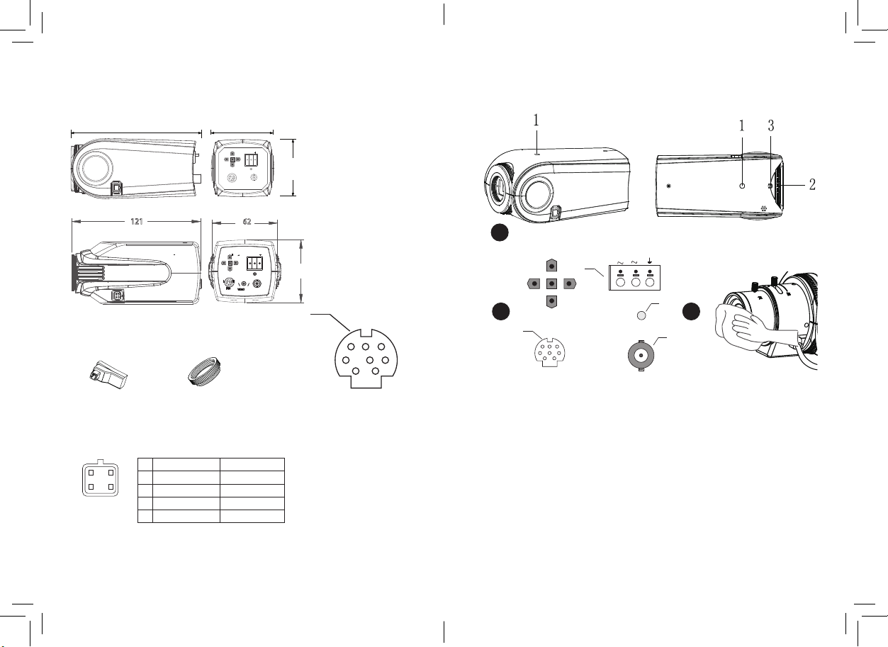
Identication
Mechanical Drawing
Installation
Installation information (General overview)
(a) Auto Iris connector (b) Adapter-ring
+
-
133 mm
5 in
71 mm
I/O
3 in
+ ~
~
64 mm
AC24V/DC12V
2 1/2 in
VIDEO
121
Accessories
DC IRIS
Pin
12
1
3
4
Figure: Auto iris
connector Jack
2
3
4
Video iris lens
Power
Null
Video signal
Ground
L
I/O
DC iris lens
62
+
~
24VAC / 12VDC
H
IRIS
Damp-
Damp+
Drive+
Drive-
1
~
VIDEO
60
I/O Connector
4
1 2 3
4 5 6
7 8
Rear I / O Interface.
1) Black RS-485+ (Efo-P & Efo-S)
2) Brown RS-485- (Efo-P & Efo-S)
3) Orange NC
4) Blue D / N_OUT night status signal
output (color: H; black & white: L)
5) Green ALARM_OUT alarm output
(motion: L; no motion: H)
6) Yellow GND to
7) White EXT_IN external trigger input
(L / NC: Day mode; H: Night mode)
8) Red POWER 3.3V DC
Note: H = 3.3V; L = GND
1 Box Camera require only a few steps for installation:
The position (1) shows the 1/4 20UNC bracket tting location one top or rear
this allows you to install in different tting locations as your bracket dictates.
(2) This is your back focus adjustment on the lens. When you install your lens
you are able to adjust back focus as different lens tend require such steps.
(3) This is the locking screw to keep the back focus position locked into place.
2 (1) Connect your video camera to the BNC connector here.
(3) Connect the 12v DC Power source or AC 24V (optional model) to terminals:
a. positive (+) wire for DC, any supply wire for AC.
3
AC24V/DC12V
LED
2
VIDEO
32
1
b: negative (-) wire for DC, other supply wire for AC.
3 With all good installations clean lens just to make sure when installed you have not
1 2
accidentally put a smear or mark which might effect the picture.
Page 3

NOTE: Make sure you don’t have any missing parts before you make the installation.
Incorrect installation could void the warranty if instructions are not followed correctly.
Please call technical for assistance if you are unsure about any procedures.
Identication
Mechanical Drawing
Installation
Installation information (General overview)
(a) Auto Iris connector (b) Adapter-ring
+
-
145 mm
145 mm
5 3/4"
5 3/4"
74 mm
3"
-
+
~
~
VIDEO OUT
64 mm
2 1/2"
24VAC / 12VDC
I/O
74 mm
3"
1
1
3
Accessories
Rear I / O Interface.
1) Black RS-485+ (Efo-P & Efo-S)
2) Brown RS-485- (Efo-P & Efo-S)
DC IRIS
Video iris lens
Pin
12
1
2
3
4
Power
Null
Video signal
Ground
3
4
Figure: Auto iris
connector Jack
3 4
DC iris lens
Damp-
Damp+
Drive+
Drive-
3) Orange NC
4) Blue D / N_OUT night status signal
output (color: H; black & white: L)
5) Green ALARM_OUT alarm output
(motion: L; no motion: H)
6) Yellow GND to
7) White EXT_IN external trigger input
(L / NC: Day mode; H: Night mode)
8) Red POWER 3.3V DC
Note: H = 3.3V; L = GND
63 mm
2 1/2"
I/O Connector
1 2 3
4 5 6
7 8
AC24V/DC12V
4
LED
2
VIDEO
32
1
1 Box Camera require only a few steps for installation:
The position (1) shows the 1/4 20UNC bracket tting location one top or rear
this allows you to install in different tting locations as your bracket dictates.
2 (1) Connect your video camera to the BNC connector here.
(3) Connect the 12v DC Power source or AC 24V (optional model) to terminals:
a. positive (+) wire for DC, any supply wire for AC.
b: negative (-) wire for DC, other supply wire for AC.
3 With all good installations clean lens just to make sure when installed you have not
accidentally put a smear or mark which might effect the picture.
Page 4

NOTE: Make sure you don’t have any missing parts before you make the installation.
Incorrect installation could void the warranty if instructions are not followed correctly.
Please call technical for assistance if you are unsure about any procedures.
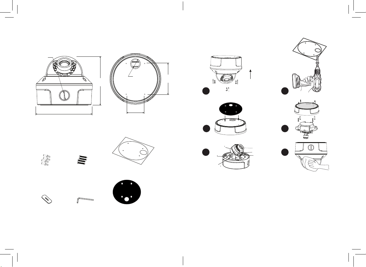
Identication
Mechanical Drawing
Installation
Installation information (General overview)
3/4’’ -14
NPS thread
4.4"
(112 mm)
Ø 98.0 mm
4 in
1
2
5.1"
(130 mm)
Base Fitting Underside
43
46.0 mm
2 in
5 6
83.5 mm
3 1/2 in
4S Mounting Plate
4S Junction Box Fitting
Accessories
(A) Wall Plugs
S8 x 30mm 4pc
5 6
(B) Fitting Screws
PA4 x 35mm 4pc
1 Unscrew the thee tamper screws to release the dome cover.
Now turn dome anti-clockwise will release base, from locking lungs.
2 Using the base as a drilled template. pre-drill all requires holes.
Fit the optional base place (A) if required to use a 4S Junction Box
3 Fitting back internal part is twist lock into place, use conduit for power if required.
4 Move camera module, and use Levels to adjust zoom/focus, twist to lock into place.
5 Reit dome cover and screw back the three tampers, this locks dome water tight.
6 Give cover a wipe clean just to remove smudges from the dome cover.
Check IR LEDs are working by covering the photocell of camera with your thumb
your thumb, the IR LEDs will give a faint red glow. (not all models have IR LEDs)
(Don’t look at IR LEDs for long periods of time, as you could damage your eyes)
Page 5
NOTE: Make sure you don’t have any missing parts before you make the installation.
Incorrect installation could void the warranty if instructions are not followed correctly.
Please call technical for assistance if you are unsure about any procedures.
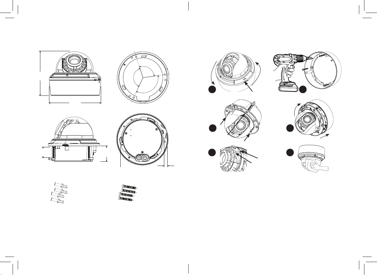
Identication
Mechanical Drawing
Installation
Installation information (General overview)
3/4” - 14
NTS thread
127 mm
5 in
3/4” 14
NTS thread
Close / Open
83.5 mm
3 1/2 in
1
2
150 mm
6 in
46.0 mm
2 in
43
Accessories
Rota te 180
5 6
Tilt 90
(A) Wall Plugs
5.6 x 29mm
(B) Fitting Screws
PA4 x 30mm
(E) Drill Template
130mm White adhesive
Pan3 60
1 Remove the dome and camera cover using the supplied L-Wrench (D)
2 Using the base as a drilled template. pre-drill all requires holes.
3 Fit the Waterproof Pad (F) to the base, with sticky side against camera.
(C) Opening Tool
50 x 1.8mm
(D) L-Wrench
T15 Size
(F) Waterproof Pad
128 x 2.5mm black EVA
4 Now ret back camera, be careful of cable so not to cut or snag.
5 Adjust position and Focus & zoom, replace cover using L-Wrench
6 Carefully clean the dome surface with a soft lint free cloth.
7 Check IR LEDs are working by covering the photocell of camera with
your thumb, the IR LEDs will give a faint red glow.
7 8
(Don’t look at IR LEDs for long periods of time, as you could damage your eyes)
Came ra body
View an gle adj ustme nt leve r
Focus a djust ment le ver
Page 6
NOTE: Make sure you don’t have any missing parts before you make the installation.
Incorrect installation could void the warranty if instructions are not followed correctly.
Please call technical for assistance if you are unsure about any procedures.
Identication
Mechanical Drawing
Installation
Installation information (General overview)
112 mm
4.4 in
5.1"
130 mm
100°
137°
Underside Base hole positionsIndoor Dome Dimensions
123°
1
2
43
27 mm
1.1 in
39 mm
1.5 in
7 mm
.28 in
5 6
Accessories
1 Press plastic clip which when pressed you can unlock and lift off the cover.
Now turn dome anti-clockwise will release base, from locking lungs.
2 (a) Using the base as a drilled template. pre-drill all requires holes.
3 (b) Using recess mount, use screwdriver will lock lungs into place and also adjust.
(A) Wall Plugs
S8 x 30mm 4pc
9 10
(B) Fitting Screws
PA4 x 35mm 4pc
Dimensions of hole must be within specications as show on Mechanical Drawing
4 Ret is matter of put dome into recess and turn clockwise to lock into place.
5 Use Levels to adjust zoom/focus, replace black cover, clip shut the dome cover.
6 Check IR LEDs are working by covering the photocell of camera with your thumb
your thumb, the IR LEDs will give a faint red glow. (not all models have IR LEDs)
(Don’t look at IR LEDs for long periods of time, as you could damage your eyes)
Page 7

NOTE: Make sure you don’t have any missing parts before you make the installation.
Incorrect installation could void the warranty if instructions are not followed correctly.
Please call technical for assistance if you are unsure about any procedures.
Identication
Mechanical Drawing
Installation
Installation information (General overview)
Standard Model IR LED Model
Release Clip
Ø 150 mm
6 in
Ceiling
109 mm
4 1/2 in
Dome base
Cut Away for
Cable side exit
150 mm
6 in
Dome cover (transparent)
(Vari-focal models)
Lens
Body Cover
Dome base
Zoom adjustment
Focus adjustment
1
BOTTOM View
5
Side cable exit
Location
Power & Video
Cable hole
Mounting Holes
Video connector
비디오 커넥터
Power connector
Type B
전원 커넥터
Type A
2
43
Dome Cover
6
1 Remove the base holding dome as shown, turn right towards you.
Rotate 180°
Align up the arrows, the dome will make a click sound and will open.
2 Using the base as a drilled template. If recess tting then can be ignored.
Pan360°
Tilt 90°
Standard Model IR LED Model
3 Fitting the cable out side of the dome you need to re-route the cable.
Remove the side cable exit screws, and back feed the cable.
4 Remove dome cover to adjust position and Focus & zoom, locate the
Clip and lift gently. Cover is on a rubber cable so won’t fall on the oor.
5 Attach power and video. Make sure power + and - are correct.
6 Carefully clean the camera with a soft lint free cloth.
7 With the IR LEDs model cover the photocell of camera with your thumb.
11 12
This checks the IR LEDs give off a faint red glow.
Page 8

NOTE: Make sure you don’t have any missing parts before you make the installation.
Incorrect installation could void the warranty if instructions are not followed correctly.
Please call technical for assistance if you are unsure about any procedures.
Identication
Mechanical Drawing
Installation
Installation information (General overview)
311 mm
12 in
99 mm
4"
Accessories
292 mm
11 1/2"
294 mm
11 1/2"
282 mm
11"
69 mm
2 1/2"
69 mm
2 1/2"
99 mm
1
4"
5 6
2
Pan Left - Right adjustment
43
View Tilt Angle adjustment
1 Remove front of camera this is just to make it easier to adjust zoom & focus later.
(A) Wall Plugs
S8 x 30mm 4pcs
(B) Fitting Screws
PA4 x 35mm 4pcs
(E) Optional Junction Box
2 Use drill template (F) as to guide to drill and attach camera to surface as required.
If you have optional junction box (E), be sure to mark the correct hole positions.
3 With camera attached you can now connect power, adjust focus/zoom.
Junction box option cable will connect inside.
4 Usng the (D) L-Hex tool you position left-right up/down and lock into place.
5 Adjust zoom-focus to suite, re-attach front section as removed in step 1.
(C) Sunshield Screw
M3 x5mm
(D) L-Hex tool
47x17mm
(F ) Drill Hole template
(Junction box holes also)
And clean surface with a soft lint free cloth.
6 Now put the sunvisor on using the (C) nut provided in the accessories.
Check IR LEDs are working by covering the photocell of camera with
your thumb, the IR LEDs will give a faint red glow.
13 14
(Don’t look at IR LEDs for long periods of time, as you could damage your eyes)
Page 9

NOTE: Make sure you don’t have any missing parts before you make the installation.
Incorrect installation could void the warranty if instructions are not followed correctly.
Please call technical for assistance if you are unsure about any procedures.
Identication
Mechanical Drawing
Installation
Installation information (General overview)
185 mm
7 1/2"
Accessories
298 mm
11 1/2"
185 mm
7 1/2"
100 mm
4"
1
Video connector
비디오 커넥터
Power connector
Type B
전원 커넥터
Type A
2
43
Focus adjustment
View Angle adjustment
(A) Wall Plugs
S8 x 30mm 4pcs
(C) Sunshield Screw
M5 Thread
(B) Fitting Screws
PA4 x 35mm 4pcs
(D) Allen Key
47x17mm
5 6
1 Remove the rear part of camera this is just to make it easier to adjust later.
2 Line up camera to surface to drill, using bracket holes with pencil mark to guide you
3 With camera attached you can now power connect. use type as tted.
4 Adjust zoom focus and position of camera to requirements. re-attach rear tightly.
5 Now slide the sunvisor on, carefull not to scratch the camera, pull sides out to help.
6 Carefully clean the dome surface with a soft lint free cloth.
7 Check IR LEDs are working by covering the photocell of camera with
your thumb, the IR LEDs will give a faint red glow.
15 16
(Don’t look at IR LEDs for long periods of time, as you could damage your eyes)
Page 10

NOTE: Make sure you don’t have any missing parts before you make the installation.
Incorrect installation could void the warranty if instructions are not followed correctly.
Please call technical for assistance if you are unsure about any procedures.
Identication
Mechanical Drawing
Installation
Installation information (General overview)
190 mm
7 1/2"
61.5 mm
2 1/2"
75 mm
3"
Accessories
75 mm
3"
Ø 62 mm
2 1/2"
1
Video connector
비디오 커넥터
Power connector
Type B
전원 커넥터
Type A
2
43
This bullet camera requires only a few simple steps for installation:
1 With hand you loosen the base, this will allow freedom to drill base into place.
Note: Base does not need to be removed from camera , illustration shown is for clarity of detail.
2 Position camera to suite make sure it is tight. Check you can’t move camera.
(A) Wall Plugs
S8 x 30mm 4pcs
(B) Fitting Screws
PA4 x 35mm 4pcs
(C) Sunshield Screw
M3 x5mm
Note: Over a long period of time temperature and conditions may effect the grip, this may drift cameras position
3 Attach power and video. Alternative power connector uses middle pin as +
4 If you had not already done so, attach sunvisor with screw, adjust to suite.
Note: Sunshield has a small variation of position, depending on angle the sunsheld may not block out the sun.
5 Check IR LEDs working by just covering the photocel of camera
with your thumb, the IR LEDs will give a faint red glow.
17 18
(Don’t look at IR LEDs for long periods of time, as you could damage your eyes)
Page 11

NOTE: Make sure you don’t have any missing parts before you make the installation.
Incorrect installation could void the warranty if instructions are not followed correctly.
Please call technical for assistance if you are unsure about any procedures.
Identication
Mechanical Drawing
Installation
Installation information (General overview)
Vari-Focal Model
120 mm
4 1/2"
70 mm
3"
70
70
12 0
70 mm
Ø 120 mm
4 1/2"
3"
Focus adjustment
Adjust wrench
1
Video connector
비디오 커넥터
Power connector
Type B
전원 커넥터
Type A
Zoom adjustment
Pan 360°
Three axis rotate
5 6
2
43
OSD Adjust
Accessories
105.5 mm
4"
1 Remove dome dome and use as drill template. Attach using plugs (A) and screws (B)
2 Once base is rmly drilled into place, re-assemble parts.
(A) Wall Plugs
S8 x 30mm 4pc
(B) Fitting Screws
PA4 x 35mm 4pc
(C) Adjustment Tool
3 Attach power and video. Connector types can be either A or B types.
4 Position camera to suite make tight using the ring, only requires hand.
5 Adjust the zoom & focus using the tool (C) provided (Vari-Focal models)
6 Adjust camera settings via the hidden OSD access point. Remove screws to access.
7 Check IR LEDs working by just covering the photocel of camera
with your thumb, the IR LEDs will give a faint red glow.
19 20
(Don’t look at IR LEDs for long periods of time, as you could damage your eyes)
Page 12

CAMERA ADJUSTMENT CAMERA ADJUSTMENT
OSD MENU control
Press down on the function joystick to access the setup menu. Product model may
RCA Service Connector
Use supplied RCA - BNC cable
If you require BNC output.
OSD function joystick. Pressing down
on joystick acts as ENTER function.
use ve directional buttons with a middle acting as the enter function.
• Main setup menu is displayed on the monitor screen.
MENU TREE SUMMARY
EXPOSURE • AUTO
• MODE • BRIGHTNESS • RETURN
• MANUAL
• MODE • SHUT • AGC • MANUAL
PIC ADJUST • MIRROR • DIS • EZOOM
• ZOOM • PAN • TILT • RETURN
• LEVEL • SHARPNESS • HUE • B-GAIN • R-GAIN
WHITE BAL • ATW
• SPEED • DELAY CNT • ATW FRAME • ENVIORNMENT
• PUSH • USER1 • USER2
• B-GAIN • R-GAIN • RETURN
• ANTI CR • PUSH LOCK
WDR • OFF • D-WDR • SUPER- WDR (Efo-P Only)
• MODE • LEVEL • HLC • CLIP LEVEL • SCALE • BLC • RETURN
DNR • OFF • 3D • 2D • 2D+3D
• LEVEL
DAY / NIGHT • AUTO • COLOR • BW • EXT
• BURST • DELAY CNT • DAY - NIGHT • NIGHT - DAY • RETURN
PRIVACY • AREA SEL • MODE • POSITION • COLOR • TRANSP • MOSAIC
MOTION DET • MOTION DET • DETECT SENSE • BLOCK DISP • MOTION AREA • RETURN
OTHERS • LANGUAGE • LENS • SYNC • CAMERA TITLE • WPC • RS-485ID
• VERSION • CAMERA RESET• AUTO IRIS • TYPE • MODE • SPEED
EXIT • SAVE ALL
SETUP MENU
SETUP MENU
EXPOSURE AUTO
PICT ADJUST
WHITE BAL ATW
WDR
DNR
DAY/NIGHT AUTO
PRIVACY
MOTION DET
OTHERS
EXIT SAVE ALL
Select a function by moving the joystick up and down and move left or right to
change setting value and press joystick to conrm selection.
If a menu option features a , a sub menu is available which can be accessed
by pressing down on the joystick.
Select ‘NEXT ’ to view remainder of the OSD setup menu
Once nished updating settings, highlight ‘EXIT’ and press down on the joystick
to exit setup menu.
To retain the changed settings after a power on/off of the camera you need to
select SAVE ALL option on the menu.
-22--21-
Page 13

CAMERA ADJUSTMENT CAMERA ADJUSTMENT
EXPOSURE
SETUP MENU
EXPOSURE AUTO
PICT ADJUST
WHITE BAL AT W
WDR
MANUAL SETUP
MODE SHUT
SHUT 1/60 (S)
AGC 6 (DB)
RETURN
Changes the output exposure settings a choice of AUTO(default) or MANUAL.
• AUTO
AUTO SETUP
HIGH LUMINANCE
MODE AE+AUTO IRIS
BRIGHTNESS
LOW LUMINANCE
MODE AGC>DSS
AGCMAX
DSS MAX X4
RETURN
032
098
• MANUAL
MODE: SHUT / SLOW / WDR + SHUT
Lets you combination of exposure modes.
Shutter, Slow Shutter, WDR and Shutter combined
SHUT: Shut can left you specify shutter speeds in xx / second
1/53 ,1/120, 1/250,1/500,1/1000,1/2000,
1/4000,1/10000
Default setting is 1/53
AGC: Set a xed gain value for the AGC db
6,12,18,24,30,36,42,44.8
MODE: AE+AUTO IRIS / ME+AUTO IRIS
Sets level of operation for using Shutter
or just Lens Iris to adjust high level exposure
BRIGHTNESS: 000-255
Brightness level of operating mode as set above.
Default setting is 128
SHUT: When MODE is set to SLOW
The shut speed can be 2,4,8,16,32,64,128,256
Default setting is 2
PICT ADJUST
Settings available only when using DC Lens.
LOW LUMINANCE
MODE: AGC/ SLOW / AGCDSS / AGC-DSS-AGC / OFF
AGCMAX: 000-255
Brightness level of operating mode as set above.
Default setting is 098
DSS MAX: X1-512
SETUP MENU
EXPOSURE AUTO
PICT ADJUST
WHITE BAL AT W
WDR
-24--23-
Page 14

CAMERA ADJUSTMENT CAMERA ADJUSTMENT
Picture and display control settings
PICT ADJUST
MIRROR OFF
DIS OFF
EZOOM
LEVEL
SHARPNESS
HUE
R-GAIN
B-GAIN
RETURN
032
009
042
104
176
• MIRROR: OFF/V-FLIP/H-FLIP/HV-FLIP
Horizontally and vertical ip the display output.
• DIS: ON / OFF Digital Image Stabilization.
• EZOOM
EZOOM SETUP
ZOOM
PAN
TILT
RETURN
000
512
256
WHITE BAL
SETUP MENU
EXPOSURE AUTO
PICT ADJUST
WHITE BAL AT W
WDR
White Balance can be set to following:
ATW / PUSH / USER1 / USER2 / ANTI CR
/ PUSH LOCK
• ATW
ATW SETUP
SPEED
DELAY CNT
ATW FRAME x0.5
ENVIORMENT INDOOR
RETURN
SPEED: 000-255 Species the AE control for ATW
Default setting is 239
DELAY CNT: 000-255 Sets the time based of ATW
ZOOM: 000-255 Default 0
PAN: 000-1023 Default 512
TILT: 000-512 Default 256
• LEVEL: 000-063 Screen brightness.
• SHARPNESS: 000-015 Screen sharpness.
• HUE: 000-100 Adjust the HUE value
• R-GAIN: 000-255 Adjust the RED gain.
• B-GAIN: 000-255 Adjust the BLUE gain.
change. Default setting is 16
ATW FRAME: x0.50 / x1.00 / x1.50 / x2.00
Sets pull in frame for magnication
Default setting is X0.50
ENVIRONMENT: INDOOR / OUTDOOR
Set the pull in frame of ATW
Default setting is OUTDOOR
• PUSH Use white balance regardless of the subject conditions.
• USER1 User dened gain adjustment on B and R
002
002
-26--25-
Page 15

CAMERA ADJUSTMENT CAMERA ADJUSTMENT
DAY/NIGHT AUTO
USER1 WB
B-GAIN
R-GAIN
RETURN
029
034
• USER2 User dened gain adjustment on B and R
USER2 WB
B-GAIN
R-GAIN
RETURN
045
038
With the dual scan CCD the WDR will give best compensation for high and low
contrast areas of the picture to not over expose.
WDR SETUP
MODE OFF
LEVEL HLC OFF
CLIP LEVEL
SCALE
BLC OFF
RETURN
• MODE: OFF / D-WDR / SUPER-WDR (Efo-P Only)
SUPER-WDR: (Efo-P) using the full double scan sensor
to produce the highest denition WDR function.
D-WDR: Gamma curve, high & low luminance adjusted
Default is Off
HLC: OFF / ON / AUTO
Highlight compensation.
000
010
B-GAIN: 000-255 B Gain adjustment for WB
R-GAIN: 000-255 R Gain adjustment for WB
• ANTI CR Activates color rolling suppression.
• PUSH LOCK Press down on joystick to set current scene as the white
balance level. Use a grey card in front of lens to give a
natural white level.
WDR
SETUP MENU
Wide Dynamic Range.
EXPOSURE AUTO
PICT ADJUST
WHITE BAL AT W
WDR
DNR
CLIP LEVEL: 000-255 Clipping level
Default setting is 0
SCALE: 000-015
BLC: OFF / ON
BLC can be enabled with WDR OFF only
DNR
SETUP MENU
EXPOSURE AUTO
PICT ADJUST
WHITE BAL AT W
WDR
DNR
DAY/NIGHT AUTO
Digital Noise Reduction.
This function reduces the background noise in a low luminance environment.
-28--27-
Page 16

CAMERA ADJUSTMENT CAMERA ADJUSTMENT
PRIVACY
DNR
DNR MODE 3D
LEVEL LOW
RETURN
BURST: ON / OFF
Selects whether to output the burst
signal when night mode has been identied.
DELAY CNT: 000-255
Night/Day identication transfer time.
DAY - NIGHT: 000-255
Threshold for Night status from day status.
NIGHT - DAY: 000-255
Threshold for the Day status from night
status.
• DNR MODE: 3D / 2D+3D / 2D / OFF
Noise reduction Filter mode.
BW SETUP: Allows additional Smart IR settings to be enabled.
LEVEL: OFF/LOW/MIDLOW/MID/MIDHIGH/HIGH
Adjustment of the lter strength.
Default setting is LOW
DAY/NIGHT AUTO / BW / EXT /COLOR
SETUP MENU
EXPOSURE AUTO
PICT ADJUST
WHITE BAL AT W
WDR
DNR
DAY/NIGHT AUTO
Day night mode, can be set to COLOR /AUTO/EXT/BW. Specify the operation of
B/W SETUP
SMART IR ON
RETURN
MODE: AUTO / USER
day&night operatios. Color will keep camera image color. Ext is for an external
trigger to activate the day/night operation.
DAY/NIGHT
BURST OFF
DELAY CNT
DAY - NIGHT
NIGHT - DAY
RETURN
003
002
005
With Mode for Smart IR Set allow user to position the Front Light
Compensation feature of the camera to a user dened rectangular area.
SMART IR AREA
TOP
BOTTOM 009
LEFT
RIGHT 017
RETURN
SMART IR SETUP
MODE AUTO
LEVEL
GAMA OPT ON
RETURN
015
001
001
-30--29-
Page 17

CAMERA ADJUSTMENT CAMERA ADJUSTMENT
SETUP MENU
MOTION DET
SETUP MENU
PRIVACY OFF / ON
EXPOSURE AUTO
PICT ADJUST
WHITE BAL AT W
WDR
DNR
DAY/NIGHT AUTO
PRIVACY
Hide an area so that it is not displayed on the monitor.
PRIVACY
AERA SEL 1 / 15
MODE OFF
POSITION COLOR TRANSP MOSAIC -
RETURN
POSITION: When selected you are presented with a modication
selection as shown such as:
NEXT: PUSH ENTER
Moving left / right / up and down, you move
each of the four corners to create any irregular
rectangle. Press Enter will change to each to each of
the four sides and highlighted by a small square box
COLOR: BLACK, RED, GEEEN, BLUE, YELLOW, CYAN, MAGENTA,
WHITE. Sets the colors of the mask frames.
AREA SEL: Selects the mask frame to be adjusted.
MODE: OFF / ON
When ON the settings below can be changed
Default all AREA are OFF
TRANSP: 1.00 / 0.75 / 0.50 / 0.00 Sets the mask transparency.
MOSAIC: ON/OFF Sets the mask frame to show as mosaic.
This MOSAIC only available if TRANSP is not 1.00
PRIVACY
AREA SEL 1 / 15
MODE ON
POSITION
COLOR WHITE
TRANSP 1.00
MOSAIC -
RETURN
MOTION DET OFF / ON
EXPOSURE AUTO
PICT ADJUST
WHITE BAL AT W
WDR
DNR
DAY/NIGHT AUTO
PRIVACY
MOTION DET
Motion Detection area of the screen, broken into 24 x 16 rectangle blocks. You
can use MONITOR AREA to give an always on detection area.
-32--31-
Page 18

CAMERA ADJUSTMENT CAMERA ADJUSTMENT
MOTION DET
MOTION DET OFF
DETECT SENSE
BLOCK DISP OFF
DETECT AREA
MONITOR AREA
RETURN
MONITOR AREA
111
AERA SEL 1 / 4
MODE OFF
TOP
BOTTOM
LEFT
RIGHT
RETURN
MOTION DET: OFF / ON. Turn on or off the motion detection.
Default is OFF
DETECT SENSE: 0-127 Sets the motion detection sensitivity level.
BLOCK DISP: ON/OFF: shows visual motion detection as block area.
DETECT AREA: Enters into separate screen to select blocked area
AREA SEL: 1/4, 2/4, 3/4, 4/4 Area number selected.
When enabled the box colour is as follow:
1 Pink, 2 Green, 3 Magenta, 4 Yellow
Overlapping areas the lower number takes priority.
MODE: OFF / ON. Master enable for the selected AREA number
DETECT AREA
EXIT: HOLD ENTER
TOP: 000-015 Moves top box area position
BOTTOM: 000-015 Move bottom box area position
LEFT: 000-023 Left side of box area position
RIGHT: 000-023 Right side of box area position.
Note: you can’t move top higher than bottom, and
left can’t be larger than right. Numbers will automatic
move when trying to move to higher position.
Monitor Area will keep the coloured box visually on the screen at all
By default the entire area is enabled for detections, using the movement arrows
you move the 2x2 size block in 12 x 8 positions around the screen, press the enter
times, and ash when motion activity occurs within the draw areas. This
works in combination with the set block areas in MOTION DET AREA.
button will toggle this area to be withing the detection. Hold down the enter
button will exit this detection area settings.
000
000
000
000
MONITOR AREA : Enters screen into setup for Rectangle Monitor Area.
-34--33-
Page 19

CAMERA ADJUSTMENT CAMERA ADJUSTMENT
SETUP MENU
EXPOSURE AUTO
PICT ADJUST
EXIT SAVE ALL
OTHERS
WHITE BAL AT W
WDR
DNR
DAY/NIGHT AUTO
PRIVACY
MOTION DET
OTHERS
• CAM TITLE OFF / ON
Camera title can be shown as name on the screen as chosen.
All functions outside the normal settings required are all withing the special menu
OTHERS
LANGUAGE ENGLISH
LENS AUTO
SYNC INT
CAM TITLE OFF
WPC
VERSION
CAMERA RESET
RETURN
Use Up/Down/Left/Right to move around. CHR1/2 changes the selection fonts to
alternative selection, CLR will clear info. POS allows position change.
• WPC
• LENS MANUAL / AUTO
AUTO IRIS
TYPE DC
MODE AUTO
SPEED
RETURN
064
This allows for white pixel compensation, to correct for CCD defects or dead pixel.
Lens cap should be put to generate a black video signal for function to work.
Permit no light to enter the sensor, respectively, the Up,Down, left, right, middle
button to start the highlight of compensation. Prompts are nished, press the
middle button to exit.
• RS485
Select ID on RS485 bus for camera, not tted on all camera types with Efo-P.
MODE: AUTO,OPEN,CLOSE
Sets the type of control to be use over a mechanical iris.
SPEED: 000-255
Sets the convergence speed of the mechanical iris.
CAMERA TITLE SETUP
CAMERA
ABCDEFGHIJKLMNOPQRSTUV
WXYZ0123456789-!#$%&’
()_`.:;<=> @^*./^*X+/
CHR1 CHR2
CLR POS
RETURN
WPC
PLEASE COVER THE LENSENTER PW
RETURN
-36--35-
Page 20

CAMERA ADJUSTMENT
SETUP MENU
EXPOSURE AUTO
PICT ADJUST
WHITE BAL AT W
• VERSION
Gives version information regarding current software inside the units.
VERSION INFO
MCU VER V1.0.0 NORMAL
ROM VER V1.0.0
RETURN
• CAMERA RESET
This will reset all settings for all menus to manufacturer
defaults. This allow you to return to shipped settings
from the manufacturer.
EXIT / SAVE ALL
WDR
DNR
DAY/NIGHT AUTO
PRIVACY
MOTION DET
OTHERS
EXIT SAVE ALL
• EXIT Exit OSD menu.
Exit will keep any changes only until camera is
powered off.
• SAVE ALL Saves the settings to camera
Settings will be retained even if the camera looses
power.
-37-
 Loading...