

Page 1

Net DVR
eLineTechnology.com
Preface
Thank you for selecting our products. We will offer the best service for you wholeheartedly.
We take 16 channel DVR (960H) as a sample. In this series, different product models’ configuration will have a little difference, and it will work the difference between product
function and operation.
It is for reference only. We will not provide any new information separately for later firmware update. The updating files will be added into the new edition of the user manual and
will also be posted on our website in the download center. This user manual may have some inaccuracy or misprint. We sincerely hope your timely feedback and comments to let us correct
and improve this booklet in the subsequent edition.
1
Page 2

User Manual
eLineTechnology.com
CONTENT
Preface....................................................................................................................................................................................................................................................................... 1
Chapter1 Brief Introduction about the DVR ............................................................................................................................................................................................................. 6
1.1 Summarization ............................................................................................................................................................................................................................................... 6
Chapter2 Technology Guideline and Main Functions .............................................................................................................................................................................................. 6
2.1 Technology Guideline .................................................................................................................................................................................................................................. 6
2.2 Main Functions ............................................................................................................................................................................................................................................. 8
Chapter3 Equipment Installation and Illustration .................................................................................................................................................................................................. 12
3.1 Installation Environment and Cautions ...................................................................................................................................................................................................... 12
3.1.1 Attentions on Installing Hard Disk ................................................................................................................................................................................................... 13
3.2 Package Checking ....................................................................................................................................................................................................................................... 13
3.3 Device Interface ........................................................................................................................................................................................................................................... 14
3.3.1 Video/Audio Connection ................................................................................................................................................................................................................... 14
3.3.2 USB Backup Interface ......................................................................................................................................................................................................................... 14
3.3.3 Network Interface ............................................................................................................................................................................................................................... 14
3.3.4 Alarm Input/Output Connection ........................................................................................................................................................................................................ 14
3.3.5 RS-485 Connection ............................................................................................................................................................................................................................ 18
2
Page 3

Net DVR
eLineTechnology.com
3.3.6 Keyboard Controlling........................................................................................................................................................................................................................ 18
3.3.7 Intercommunication Port .................................................................................................................................................................................................................... 18
3.4 Front Panel Description ............................................................................................................................................................................................................................. 19
3.5 IR Remote Controller Operation ................................................................................................................................................................................................................. 22
3.6 Mouse Operation ........................................................................................................................................................................................................................................ 24
3.7 Menu Operation Description ...................................................................................................................................................................................................................... 26
3.7.1 Menu Structure Chart ......................................................................................................................................................................................................................... 26
3.7.2 Menu Option Schedule ...................................................................................................................................................................................................................... 27
Chapter4 Device Operation .................................................................................................................................................................................................................................... 33
4.1 Power On/0ff and Login /Lock ................................................................................................................................................................................................................... 33
4.1.1 Keystroke Unlock/Lock .................................................................................................................................................................................................................... 33
4.1.2 System Login ..................................................................................................................................................................................................................................... 33
4.1.3 System Lock ....................................................................................................................................................................................................................................... 34
4.1.4 Main Menu ......................................................................................................................................................................................................................................... 34
4.1.5 Status Bar ........................................................................................................................................................................................................................................... 34
4.2 Power on Wizzard ....................................................................................................................................................................................................................................... 35
4.3 Data Inquiry and Playback ......................................................................................................................................................................................................................... 36
4.3.1 Time Inquiry ....................................................................................................................................................................................................................................... 36
4.3.2 Event Inquiry ..................................................................................................................................................................................................................................... 36
4.3.3 Data Management ............................................................................................................................................................................................................................... 39
4.4 Backup Management ................................................................................................................................................................................................................................... 39
3
Page 4

User Manual
eLineTechnology.com
4.4.1 Quick Backup..................................................................................................................................................................................................................................... 40
4.4.2 Manual Backup .................................................................................................................................................................................................................................. 40
4.4.3 Schedule Backup ................................................................................................................................................................................................................................ 40
4.5 Record Setup ............................................................................................................................................................................................................................................... 41
4.5.1 Record Parameter ................................................................................................................................................................................................................................ 41
4.5.2 Screenshots Parameter ........................................................................................................................................................................................................................ 42
4.5.3 Advanced ........................................................................................................................................................................................................................................... 42
4.5.4 Manual Record ................................................................................................................................................................................................................................... 43
4.5.5 Manual Snapshot................................................................................................................................................................................................................................ 43
4.5.6 Schedule Record ................................................................................................................................................................................................................................. 44
4.6 Alarm Setup ................................................................................................................................................................................................................................................. 44
4.6.1 Motion ............................................................................................................................................................................................................................................... 44
4.6.2 Sensor ................................................................................................................................................................................................................................................. 46
4.6.3 Alarm Output ..................................................................................................................................................................................................................................... 46
4.6.4 Other Alarms ...................................................................................................................................................................................................................................... 47
4.6.5 Manual Alarm ..................................................................................................................................................................................................................................... 47
4.7 System Setup ............................................................................................................................................................................................................................................... 48
4.7.1 General Setting .................................................................................................................................................................................................................................. 48
4.7.2 Time Setting ....................................................................................................................................................................................................................................... 49
4.7.3 Output Setting ................................................................................................................................................................................................................................... 50
4.7.4 COM Setting ...................................................................................................................................................................................................................................... 53
4.7.5 PTZ Setting ........................................................................................................................................................................................................................................ 54
4.7.6 Network Setting ................................................................................................................................................................................................................................. 56
4.7.7 Input Settings..................................................................................................................................................................................................................................... 61
4.8 HDD Management ....................................................................................................................................................................................................................................... 61
4
Page 5

Net DVR
eLineTechnology.com
4.8.1 Basic Information................................................................................................................................................................................................................................ 62
4.8.2 HDD Group ....................................................................................................................................................................................................................................... 63
4.8.3 SMART .............................................................................................................................................................................................................................................. 63
4.9 Information Inquiry ..................................................................................................................................................................................................................................... 63
4.9.1 System Information ............................................................................................................................................................................................................................. 64
4.9.2 Record Status ..................................................................................................................................................................................................................................... 64
4.9.3 Alarm Status ....................................................................................................................................................................................................................................... 65
4.9.4 Online Status ..................................................................................................................................................................................................................................... 65
4.9.5 Log Inquiry ........................................................................................................................................................................................................................................ 66
4.9.6 Input State .......................................................................................................................................................................................................................................... 66
4.10 System Maintenance .................................................................................................................................................................................................................................. 67
4.10.1 Quick Settings ................................................................................................................................................................................................................................. 67
4.10.2 User Management ............................................................................................................................................................................................................................. 67
4.10.3 Reset to Default ................................................................................................................................................................................................................................ 68
4.10.4 Upgrade Management ....................................................................................................................................................................................................................... 69
4.10.5 Timing to Restart .............................................................................................................................................................................................................................. 71
4.11 Logout/Shutdown/Reboot ....................................................................................................................................................................................................................... 72
4.12 Password Reset ......................................................................................................................................................................................................................................... 72
4.13 Power Resume ........................................................................................................................................................................................................................................... 72
Appendix 1: IE Operation Instructions .................................................................................................................................................................................................................. 73
1. LAN Configuration for IE Browse ............................................................................................................................................................................................................... 73
2. WAN Operation Instructions ....................................................................................................................................................................................................................... 74
Appendix 2: Net DVR Q&A ................................................................................................................................................................................................................................... 77
5
Page 6

User Manual
eLineTechnology.com
Chapter 1 Brief Introduction about the DVR
1.1 Summarization
The series DVR are designed for video/audio digital surveillance system. They are adopting H.264 compress format, integrate the embedded RTOS and processor to realize all of the
functions like video and audio acquisition and compression, storing, remote control, Multi-PTZ control and alarm in a single board. This series DVR achieve the integrate host to a
single plate structure, which ensure the system’s high-integration and reliability.
This series of equipment use private file systems MFS V2.0, namely flow media file system second edition. This file system is based on Microsoft FAT32 to innovate, suitable for DVR
special file system, support more than 2TB hard disk; Long time operation does not produce disk fragments; Reasonable flow media operation scheduling, the operation has fast response;
Increase check protection in the MFS key information, avoid key areas damaged cause to catastrophic problem.
This device can be the local independent work, also can build a strong safety monitoring system by network. Can be applied to Banks, telecommunications, electric power,
transportation, intelligent community, factory, warehouse, etc.
Chapter 2 Technology Guideline and Main Functions
2.1 Technology Guideline
1. Video parameters
Video input: Composite video input, PAL (25fps), NTSC (30fps), BNC (1Vp-p, 75
Ω)
6
Page 7

Video output:
eLineTechnology.com
1 channel composite video output, PAL (625 line), NTSC (525 line), BNC (1Vp-p, 75
1 channel analog video output (VGA)
2. Audio parameters
Audio input: RCA interface port, input resistance: 10K , input extent: Vp-p=2.0V LINE
Audio output: RCA interface, input resistance: 10K , input extent: Vp-p=2.0V LINE
Voice chat: Input (3.5MM interface, input resistance: 10K , input extent: Vp-p=2.0V LINE in/50mV MIC in)
3. Video compression: Compression arithmetic H.264
Default resolution FD1: PAL (704*576) 25 fps/ch, NTSC(704*480) 30 fps/ch;
Resolution 960H: PAL (928*576) 25 fps/ch, NTSC (928*480) 30 fps/ch.
4. Audio compression: Compression arithmetic G.711A, Audio sampling rate 8K sample/sec., 16 bit/sample
5. Code stream type: VBR/CBR
6. Operation System: Linux
7. HDD interface: support 48bit LBA working mode
8. Alarm interface
Alarm input: Alarm input support normal on/off
Alarm output: Normal on, relay output
9. Serial interface: Support RS485 half-duplex, network transparent and COM control keyboard
10. Operation mode: multi-functional IR remote control, USB mouse, serial keyboard
11. Backup interface: USB2.0 interface
12. Network port: RJ45 10M/100M/1000M Ethernet Interface
13. Power supply: 220 ± 30% V, 50 ± 3% HZ, 110 ± 20% V, 60±3% HZ
Ω
Ω
Ω
Ω)
Net DVR
7
Page 8

User Manual
eLineTechnology.com
2.2 Main Functions
High effective RTOS and embedded processor are adopted in this series DVR, as well as all functions needed for the monitoring system are integrated. Code is solidified in the flash
chip to keep the system in high stability and reliability. System can also work in a long time surveillance environment and even in stringent circumstance.
Note: The following features might differ from the below description since we have series products and different hardware and software versions.
u Compression features
1. Support PAL/NTSC video format signal.
2. Video compression algorithm is H.264.
3. Video and audio signals are compressed into H.264 code stream. Audio and video stream are synchronous when playback, and audio recording can be canceled if only video is
in need.
4. Audio compression algorithm adopts G.711A, and every video/audio signal is compressed separately in real time, then generate composite compressed code stream. The video
and audio stream are synchronous when playback, or setting disable audio with the sampling rate of 8K sample/sec., 16 bit/sample.
5. Supporting dual stream compression: main code stream used for local storing, sub code stream used for image transmission in low-bandwidth network.
6. 6 levels of record quality is available to select. Users can choose according to requirements so that the recording time is long enough.
u Recording function
1. Support 4 record modes: manual, schedule, motion and alarm recording.
2. Support 5 screenshot modes: manual screenshot; manual, schedule, motion and alarm snapshot.
3. Video motion detection function: multi detection areas can be set up to 5 sensitive levels.
4. Support screen shield. Each channel can max setting 4 mask areas, support preview mask, record mask and all mask.
5. Each channel support 4 interested area setting.
6. Support sensor alarm. One sensor can be linked to one or more cameras. Support alarm recall to PTZ preset point.
7. Monitoring center can record the real time compression code stream, and support synchronizing record video and audio into client PC.
8. Video and audio parameters of each camera can be set up separately.
8
Page 9

9. Support channel title and recording time superpose.
eLineTechnology.com
10. Support multiplex operation, can real time recording without impacting other functions.
(such as playback, fast forward, slow playback, rewind, network monitor, VOD and remote)
11. Support pre-record feature, and pre-record time is 5-30 seconds.
12. Support record status inquiry function.
u Playback functions
1. Support inquiry recording files/pictures by time, fix position by time to record/pictures playback.
2. Support inquiry recording files/pictures by event, as per channel number/record type to inquiry/record/pictures playback.
3. Support intuitive video information graphical display and play.
4. Support zoom in on playback.
5. Support full realtime quick playback.
6. Support inquiry other time/channel recording files through list to playback.
u Real time survillance features
1. Support HDMI, VGA, CVBS dual output with different source.
2. Support SPOT sequence output.
3. Support 1/4/8/9/13/16 ch preview, the order of channels can be adjusted and the time position in preview also adjustable.
4. Support 24Hour/12Hour mode switching.
5. Support DST.
6. Support zoom in.
7. Support mask some parts of area or all.
8. Support adjust video parameter (brightness, contrast, and saturation, hue) for each channel.
9. Support cruise.
10. Support intercom.
11. Support a variety of mainstream PTZ decoders control protocol, support preset point, PTZ preset point cruise and trajectory cruise.
Net DVR
9
Page 10

User Manual
eLineTechnology.com
u Storing and backup functions
1. Support maximum 2 SATA HDD.
2. Support data lock/unlock/delete for all recording files/pictures.
3. The maximum saving time of recording files/pictures can be set, the DVR will auto delete the data which exceed the setting time.
4. Support set read-only/read-write to HDD.
5. Support HDD quota management, different channels can be arranged different quota for save data.
6. Support USB backup (USB disk or external USB burner).
7. Support backup by internal burner.
8. Support batch backup as per files.
9. Support clipping for backup while playback.
10. Support log backup.
11. Support backup record files by IE browser.
12. Powerful hard disk management function, support HDD dormancy and format, support the damaged partition shield, bad disk to eliminate and alarm mechanism.
u Alarm inspection functions
1. Local alarm: manual alarm, video lost alarm, motion detection alarm, sensor alarm, HDD faulty alarm, temperature alarm, network disconnect alarm, video shield alarm.
2. Video lost alarm, motion detection alarm, sensor detection alarm response on time.
3. Network alarm linkage (upload alarm signal), sound alarm through the PC own horn.
4. Video motion detection function, each channel can be set several detection area.
5. Support upload alarm information by email, send alarm channel/type/pictures to the assigned email.
6. Support motion detection and sensor detection jump to PTZ preset point.
u Network functions
1. Support TCP/IP protocol (support ARP, RARP, IP, TCP, PPPOE, DHCP, DDNS).
2. Support 3G and ADSL dial-up network connection, and support auto-redial after disconnect.
3. Perfect network-end control order (Client manager and IE browse can be used to control the DVR, such as setting the parameters, remote upgrade, etc).
4. Support composite channel preview through IE browser.
10
Page 11

Net DVR
eLineTechnology.com
5. Support control PTZ/lens/wiper by network.
6. Firmware upgrade through network makes after sale service much easier.
7. Support FTP upgrade.
8. Support NTP timing.
9. Support DDNS.
10. Support alarm upload by email (video lost, motion detection, alarm detection).
11. Support mobile phone survillance.
12. Support email test and DDNS test.
u Security guarantee
1. High quality 32 bits embedded microprocessor and embedded RTOS, which ensure the system’s high-affectivity, reliability and stability.
2. Perfect log search function.
(such as sensor record log, motion detection record log, remote login log, record parameter modification log, update log, playback log, system start-up log, backup log)
3. System lock, keystroke lock, password verification, multi-level user authorization (using the username and password as encryption key of code stream when transmission).
4. Video lost alarm, motion detection alarm and sensor alarm can be informed by email.
5. Network alarm linkage (alarm signal can be uploaded).
6. Watchdog function. When the system is abnormal, watchdog automatically detects and reboots the system.
u Exploitation support
Client manager software and client management SDK.
11
Page 12

User Manual
eLineTechnology.com
Chapter 3 Equipment Installation and Illustration
3.1 Installation Environment and Cautions
Installation environment:
●Normal working temperature is -10℃-55℃. Storage temperature is -10℃-70℃.
●Normal working humidity is 15%-85%.
●The equipment must keep horizontal either in installation or on using.
● Avoid installing in high temperature or humidity conditions.
●Heat release fans are placed for cool down, so you should put the device on ventilated place.
●The back of Net DVR should be placed 6cm away from the other device or wall while installing.
●Moving the Net DVR between two places with high difference in temperature will shorten the using life.
●Please install the lightning conductor when the machine is used in frequent thunder areas.
●The HDMI cable must be with magnetic ring.
Cautions:
●Don’t touch the power switch or the Net DVR by wet hands.
●Make sure the machine and its case are grounded (There is an earth interface on the back panel of the machine).
●Keep the power supplier stable to avoid abnormal power cut off.
●Avoid dropping liquid or metal into machine that may cause short circuit or fire.
●Don’t record or playback until at least one HDD is installed.
●Short circuit would happen when moist dust is on the board, so user has to termly brush the board and other accessories to make the machine work in good condition.
12
Page 13

Net DVR
eLineTechnology.com
●Video/audio/RS485 devices can’t be plug or draw when the power is on, or else the equipment will be easily damaged.
●Use the power on/off button on the front panel instead of direct shut off the power directly when turn off the Net DVR, so that the hard disk won’t be damaged.
●After installation, machine can automatically detect hard disk. If an unformatted hard disk is detected, system will give off information whether to format the disk (the dvr support
format HDD, don’t need operate in PC).
●Warning: Don’t try to plug in HDD to PC if not specialized persons, the following operation of HDD on PC will cause HDD can’t be recognized and need format when plug in
at next time:1,modify or edit the file name. 2,open the file and edit the content. 3,copy back the data which copied out before to HDD again. 4,Some third party browser software will
also change HDD physical storage locationin the background.
● Don’t open the cover before power off.
●In order to ensure the integrity of the video data, if found that HDD was damaged please promptly replaced (log has the record of HDD faulty).
3.1.1 Attentions on Installing Hard Disk
1. Recommend high speed hard disk above 7200 rpm.
2. The capacity of the single hard disk is above 32GB at least, each HDD can max support 3TB.
3. The selection and calculation for capacity:
Total capacity= channels number * record time needed (hours) * capacity per hour (M/hour)
For example: If you choose the recording bit rate type for CBR 2Mb (refer to 4.3 for bit rate types), the HDD Capacity /hour/channel=bit rate(Mbps) * 3600s=2Mbps*3600s=7200Mb,
because 1MB=8Mb, so the data capacity of each channel/hour when choose CBR 2Mb is 7200Mb/8=900MB.
3600s=1800MBb=225MB (1MB=8Mb). Due to the various factors, the calculated result is for reference only. Some slight differences or small errors might exist in the calculation.
Audio recording capacity is about 30MB per camera per hour. In order to save HDD space, we suggest closing the audio except users mandatory require audio recording.
Notes: When HDD is full, the default set will let system overwrite the earliest 1 day recorded files, please consider this situation when calculate the HDD capacity.
4. The attachments, such as data cable, power line, and hard disk are prepared well.
Notes: This series DVR don’t support the hot swap, please install the HDD and connect the data line first then plug the electricity in.
3.2 Package Checking
After open the box, please check the DVR whether was distorted or damaged. If there have, please do not use it and contact your suppliers in time. Meanwhile, please check all
accessories of the DVR; do read the attached information carefully. ( Notes: Accessories as for the packing list)
13
Page 14

User Manual
eLineTechnology.com
3.3 Device Interface
3.3.1 Video/Audio Connection
Video output: 1 VGA output, 1 HDMI output, 1 composite video signal output.
Audio output cautions: connect sound box or MIC output.
3.3.2 USB Backup Interface
The U disk for backup should be FAT32 format. If you want to format the U disk, please enter the “HDD Management” to check it.
(Specific operation please refer to “HDD Management” ) The U disk backup operation please refer to “Backup Operation”.
3.3.3 Network Interface
There is a RJ45 10M/100M/1000M adaptive Ethernet interface which is used to connect the PC and the DVR.
The indicator lights ACT and LINK are used to indicate current network status.
LINK (Network speed indicator) green lights—1000M /100M off —10M
ACT (Send/Receive data indicator) Blink—Sending/Receiving data
3.3.4 Alarm Input/Output Connection
Alarm input: Input resistance: 22K , window contrast voltage (3.0V-4.18V).
(Note: There will be alarm when the voltage between 0V-3V or 4.18V-12V, and no alarm when the voltage between 3.0V-4.18V)
Alarm output: Relay (240VAC/7A, 125VAC/10A, 28VDC/10A), normal (relay open), alarm output (relay close).
Sensor power: The machine provides a +12V DC power output port.
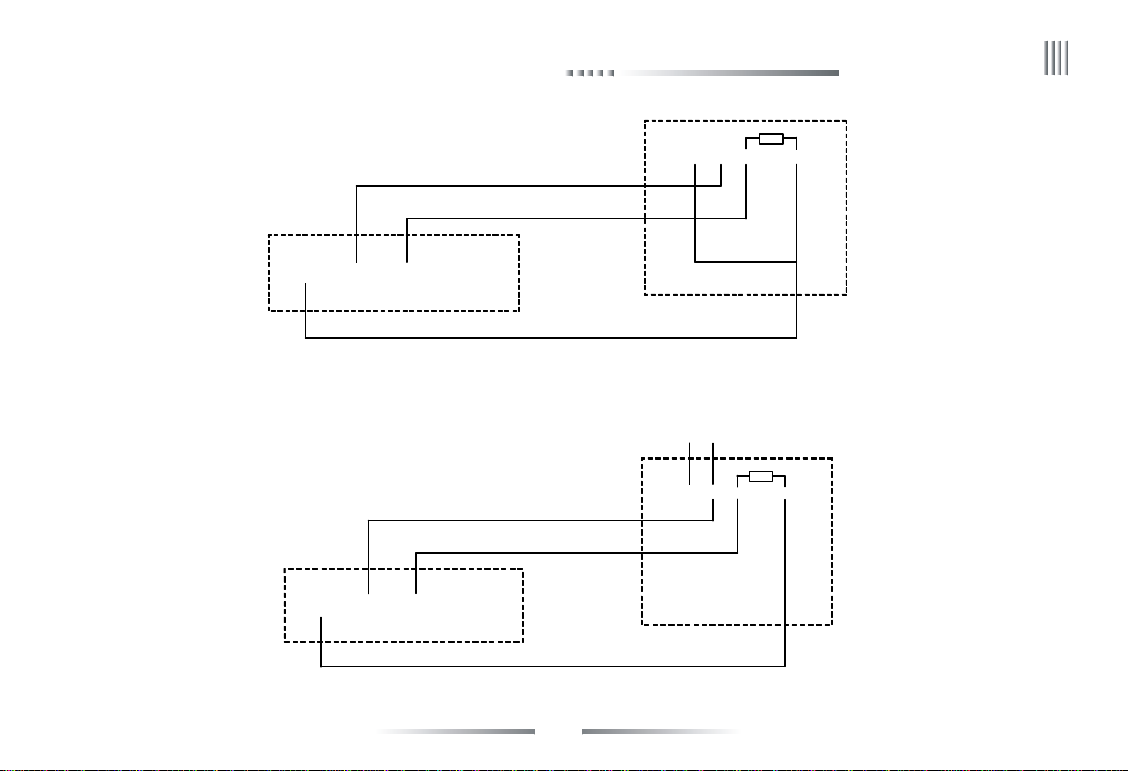
1. Alarm sensor connection:
Alarm input: The physical connections of the normal on/off mode are the same. And user can select normal on/off mode in the DVR.
Note: The alarm input port which haven’t used should be closed in the DVR.
Typical alarm connection: the sensor power supply is provided by DVR. The fig is as follows:
Ω
14
Page 15
Net DVR
DVR
NO/NC
12V power supply
eLineTechnology.com
-
NO/NC+
C
+12V GND Input1 Input2
If the distance between the probe and DVR is too far, the probe requires a separate power supply:
Please connect 2 side to ground if conditional when use separate power, otherwise long distance transmission maybe make false alarm.
DVR
+12V GND Input1 Input2
+
15
Sensor
-
Sensor
C
Page 16
User Manual
eLineTechnology.com
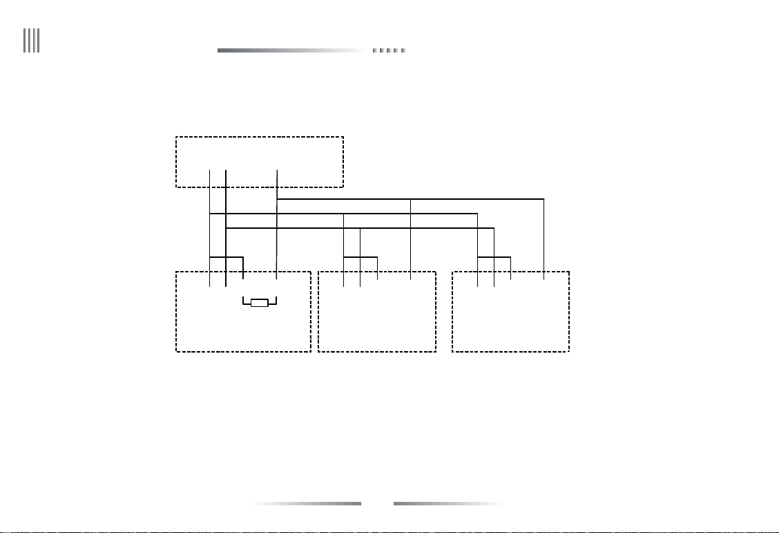
If we parallel connected the sensor, the DVR can not recognize the triggered sensor. User need to have a resistance.
-
DVR
C
-
NO/NC+
C
NO/NC+
+12V GND Input1 Input2
-
C
NO/NC+
Sensor1 Sensor3Sensor2
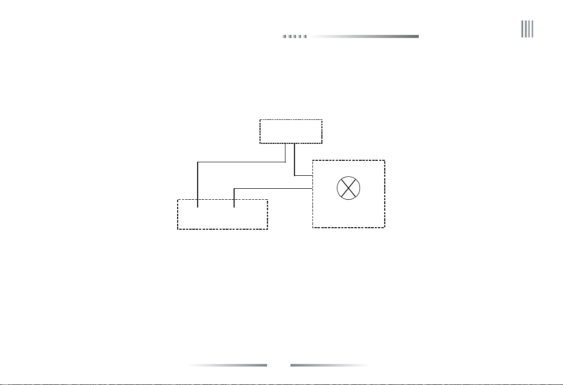
2. Alarm output connection:
The alarm output side is normal-off and do not have voltage output. The other alarm equipments (loudspeaker, light, alertor) need the individual power supply.
16
Page 17
Net DVR
Output1A Outnput1B
DVR
eLineTechnology.com
supply the
power separately
Alarm
Normally, Alarm’s power usually is much bigger, preferably supply power separately, and do not use the DVR’s power to supply.
Each series alarm output critical parameters are as follows: 240V/AC7A, 125V/AC10A, 28V/DC10A. Exceeding these parameters will damage the motherboard.
17
Page 18

User Manual
eLineTechnology.com
3.3.5 RS-485 Connection
Attentions for PTZ decoder connection:
1. Confirm that the PTZ decoder and Net DVR are one point ground connected, or common mode voltage might exist to cause the PTZ invalid.
2. Prevent high voltage inroad, carefully dispose connection cables secure thunder proof.
RS485: For PTZ control, serial keyboard and transparency port connection. (through network to control PTZ etc.)
3.3.6 Keyboard Controlling
If you want to unify control more than one DVR, you have to use the series keyboard (we suggest user using one series keyboard to control more than one DVR in the same model).
The function of the keyboard is the same with the front panel of DVR. (Note: the keyboard must be added with the protocol from our company and go through the test of our company).
Take the RS485 interface series keyboard for example:
1. “Main Menu” -> “System Setup” -> “COM”, to setup the COM number and COM device (series keyboard).
2. Connect between RS485+ of the keyboard and RX+ of the DVR, also RS485- of the keyboard and RX- of the DVR.
3. Connect with the power supplier.
4. Choose the “Switch” key to change mode to DVR mode, the default is “DVR-01”, “01” is address code of keyboard.
5. Address code of keyboard: choose the “shift” key to enable the up key of the keyboard, then click “address/enter” to
input the host address code, then you can control the DVRs.
Note: The detail set of keyboard can refer to the user manual of keyboard.
3.3.7 Intercommunication Port
There is a “MIC” port on the back panel, support the active or passive microphone.
18
Page 19

3.4 Front Panel Description
eLineTechnology.com
S.N Name Mark Note
Net DVR
1 (Power) On/Off
2
(Number/Letter)
3
(Function keys)
Number/Letter
Shift (Zoom+)
Turn on/off DVR.
1. For video channel shift, 1-8 number corresponds to CH1-CH8.
0-9/A-Z
*/Preset It means preset when in the PTZ control status.
#/Call It means call when in the PTZ control status.
PTZ Press the PTZ key, when light on, it’s in PTZ control, press again to cancel the PTZ control.
Login/Lock
(Auto)
2. The number keys are used for switch channels when playback mode.
3. When setting parameters, select number and English letter input.
1. Be used to login or lock system.
2. It means auto when in the PTZ control status.
1. Shift real time display.
2. It means “zoom+” when in PTZ control status.
19
Page 20

User Manual
eLineTechnology.com
3
(Function keys)
4 (Shortcut
key for menu)
Format
(Zoom-)
Image (Iris)
Clear (Iris-)
Page up
(Focus+)
Page down
(Focus-)
Return
(Wiper)
Rec. Enter the manual record rapidly in without menu status.
Playback Enter the playback rapidly in without menu status.
Backup Enter the backup rapidly in without menu status.
Information Enter the system info. rapidly in without menu status.
Menu Enter the main menu rapidly in without menu status.
1. Shift between single and multi channel video when in real time display.
2. It means “zoom-” when in PTZ control status.
1. Set parameters of each channel, without menu state is valid.
2. It means “iris+” when in PTZ control status.
1. Edit cancel. 2. Alarm clear.
3. It means “iris -” when in PTZ control status.
1. The drop-down menu option switch.
2. It means “focus+” when in PTZ control status.
1. The drop-down menu option switch.
2. It means “focus -” when in PTZ control status.
1. Exit and return to the up menu.
2. It means wiper when in PTZ control status.
20
Page 21
Net DVR
eLineTechnology.com
5 (Indication
lamp area)
6 (Direction key)
POWER
HDD Hard disk indication: It’s light when the hard disk is working or it’s off.
IR IR remote controller indication lamp, it’s light when you use the IR remote controller.
ALARM Alarm indication lamp: it’s light when there is alarm or it’s off.
LOCK Lock indication lamp: it’s light while the remote controller is lock.
NETWORK Network indication lamp: it’s light while the network is connected.
PTZ PTZ indication: It’s light while entering PTZ controlling status, or it’s off.
UP/Slow play
Down/Frame on
Left/FB
Right/FF
OK/Play/Pause
Shuttle turn left
and turn right
While supply power to DVR and the system running, this lamp will be lighted.
When power supplier cut off, this lamp will be off.
1. Cursor move; 2. Slow play; 3. It means up while in PTZ control.
1. Cursor move; 2. Frame on; 3. It means down while in PTZ control.
1. Cursor move; 2. FB; 3. It means left while in PTZ control.
1. Cursor move; 2. FF; 3. It means right while in PTZ control.
1. Confirm select; 2. Play/Pause.
1. Cursor move;
2. Turn left means FB, turn right means FF while in playback status.
21
Page 22
User Manual
eLineTechnology.com
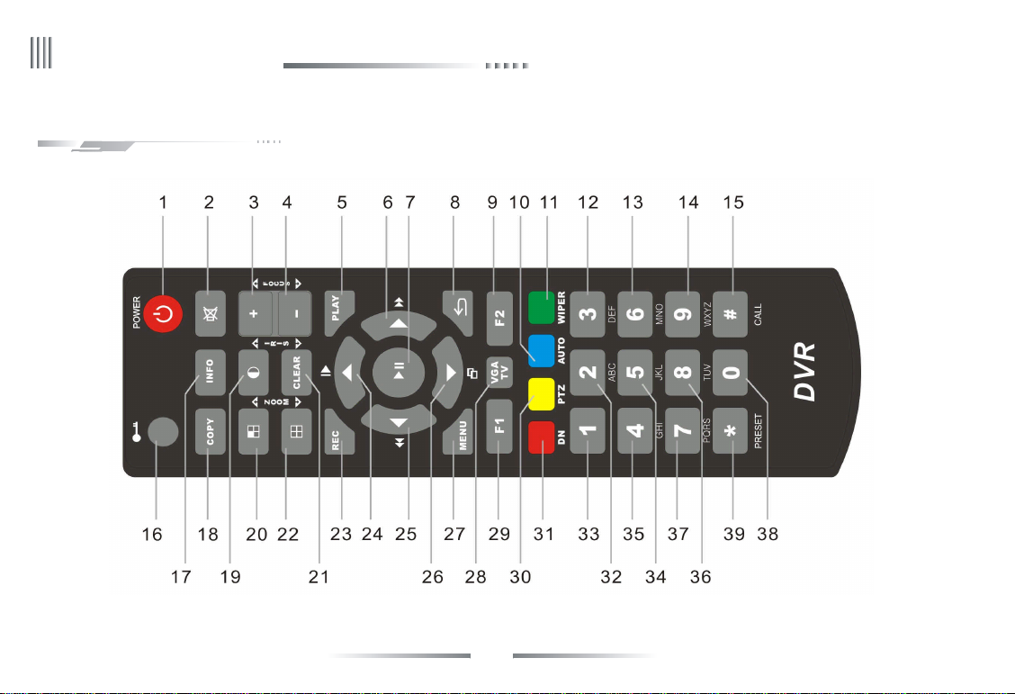
3.5 IR Remote Controller Operation
22
Page 23

1. Power 14. 9WXYZ 27. Menu
eLineTechnology.com
2. Mute 15. CALL 28. VGA/TV
3. +, Focus+ 16. Log in/Log off 29. F1
4. -, Focus- 17. Information 30. PTZ
5. Playback 18. Backup 31. Server Index
6. Right/Fast Forward 19. Image/Iris+ 32. 2ABC
7. OK, Play/Pause 20. Shift/Zoom+ 33. 1
8. Return 21. Clear/Iris- 34. 5JKL
9. F2 22. Format/Zoom- 35. 4GHI
10. Auto 23. Record 36. 8TUV
11. Wiper 24. Up, Slow Motion 37. 7PQRS
12. 3DEF 25. Left, Backward 38. 0
13. 6MNO 26. Down, Frame Forward 39. *, Preset
(Note: F1 and F2 are preserved functional keys.)
Net DVR
Keystroke instruction
23
Page 24

User Manual
eLineTechnology.com
3.6 Mouse Operation
Besides front panel and remote controller, mouse also can be used to control the DVR’System.
Right click the mouse:
1. If the system is in login status, right click the mouse, then shortcut menu will display as right picture:
2. If DVR is locked and in real time monitor status, the login menu will pop out when right click the mouse. The system default
setting user name is “admin”, and password is 888888 (Left click mouse to open soft keyboard. Right click mouse in blank area
to close soft keyboard after finish inputting).
3. Once entering the menu, right click the mouse, it will let you exit the current interface and back to the former menu or exit the
main menu. (right click mouse has same function with close when have menu)
4. If have soft keyboard in login interface, right click mouse on soft keyboard after input, the soft keyboard will be disappeared.
Left click the mouse:
1. Left click the mouse, and you will enter the functional menu.
2. In the main menu, left click the close icon at the right up corner to close the menu and return to the up one level.
3. In the main menu, left click to access or set up the parameters.
4. When selecting the motion detection setup, left click the mouse to change the status of the motion detection square unit.
5. To set up the video images parameters, you can change the brightness, contrast, saturation, hue of the image by left click the mouse on a certain point you prefer.
6. For input box, left click to enable the soft keyboard (the default is english character soft keyboard, click the Caps to shift the case), continuous click the icon of the right of
input box can switch to different soft keyboard (number, symbol, English character ), mean can input number, character, symbol, clear, space, enter etc.
7. In split-screen format preview, long press the mouse left key and drag the channel to other channel position then loosen to change the channel display position.
8. In real time preview, long press the mouse left key and drag the time to the needed position then loosen to change the time display position.
24
Page 25

Double left click the mouse:
eLineTechnology.com
1. Double left click in preview can switch single channel and multi channel.
2. Double click the mouse can clear the mask area and motion area.
3. After callout the PTZ control interface, double click the mouse to move the PTZ control interface to pointing place.
Soft keyboard interface as below:
Net DVR
25
Page 26

User Manual
eLineTechnology.com
3.7 Menu Operation Description
3.7.1 Menu Structure Chart
Backup
Data
inquiry
management
Record
setup
Alarm
setup
Main Menu
System
setup
HDD
management
Information
inquiry
System
maintenance
Shutdown
Event inquiry
Time inquiry
management
Data
Quick backup
Schedule
backup
backup
Record
parameter
parameter
Manual
Advanced
Screenshots
record
Motion
snapshot
Manual
Alarm output
Sensor
Schedule
Manual
Manual alarm
Other alarms
General
Time
setting
Channel
Output
COM
Sequence
OSD
26
Input settings
PTZ setting
Network
Network
Sub-stream
Basic
information
PPPOE
DDNS
SMART
HDD group
Email setting
Server
channel
System
information
Compound
Record status
Online status
Alarm status
Log inquiry
Input state
Quick settings
to default
Account
Logout
Reset
management
Shutdown
to restart
Upgrade
Reboot
Timing
Page 27

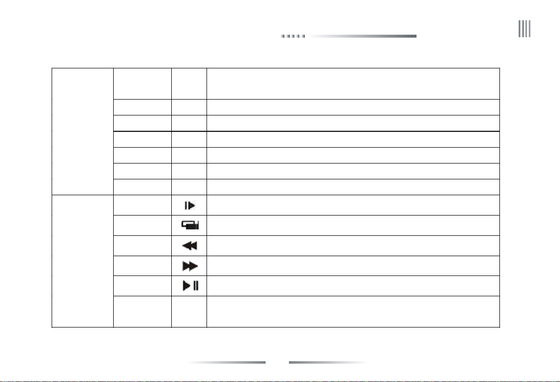
3.7.2 Menu Option Schedule
eLineTechnology.com
Net DVR
Menu
Data Inquiry
Backup Management
Record Setup
Instruction
Time Inquiry Query the record/pictures by time, and with video data graphical display to precise playback.
Event Inquiry Query and playback by event type of record/pictures.
Data Management Lock/unlock/delete the files.
Backup/inquiry/playback for record/pictures (quick, schedule, manual).
1. Record mode: all, manual, schedule, motion detection and alarm record;
2. Bitrate type: VBR, CBR;
3. Definition: FD1, CIF;
Record
Parameter
Screenshots
Parameter
4. Image quality: 6 level (highest, higher, high, middle, low, lowest);
5. Frame rate: 2-25 fps adjustable;
6. Bitrate: 512K, 768K, 1M, 1.5M, 2M, 3M, 4M (FD1); 100K, 256K, 512K, 768K, 1M (FD1);
7. Audio: enable indicate record audio, unable indicate don’t record audio, the digital audio and
analog audio can be chose;
8. Pre-record time (5-30S), delay record time (0-180S).
1. Screenshot type: manual, schedule, motion, Alarm;
2. Definition: FD1, CIF;
3. Image quality: 6 level (highest, higher, high, middle, low, lowest);
27
Page 28

User Manual
eLineTechnology.com
Record Setup
Alarm Setup
Screenshots
Parameter
Advanced
Manual Record Enable manual record.
Manual Screenshot Enable manual screenshot.
Schedule Record Enable schedule record. set the record deployment time period, channel copy function.
Motion
Sensor
Alarm Output 1. Alarm during time, audio, buzzer, full screen; 2. Deployment time of output alarm.
Other Alarms
Manual Alarm Test alarm output by manual, trigger alarm or close alarm but manual when happen urgent things.
4. Screenshot period: 1-5S, screenshot Number: 1 pcs (schedule, motion, alarm);
5. Enable the screenshot (schedule, motion, alarm).
1. Overwrite: auto, manual;
2. Maximum days of record saving: 1 week, 1 month, 1 year, Unlimited;
3. Maximum days of pictures saving: 1 week, 1 month, 1 year, Unlimited.
1. Motion detect sensitivity: 1-5 level (5 is the highest);
2. Set motion detection area, time, channel copy function;
3. Linkage setting: triggered record, screenshot linkage, alarm output, email linkage, PTZ preset point.
1. Sensor type: normal on/off ; 2. Sensor number, deployment time, channel copy function;
3. Linkage setting: triggered record, screenshot linkage, alarm output, email linkage, PTZ preset point.
1. Alarm type: HDD faulty, video lost, network disconnect, over temperature, video shield;
2. Alarm linkage: alarm output, email linkage.
28
Page 29

System Setup
eLineTechnology.com
Net DVR
1. Host name, Open remote control lock, Host id; 2. Video standard: PAL/NTSC;
3. Resolution: 1024*768, 1280*1024, 1440*900, 1920*1080;
General Setting
Time Setting
Output Setting
COM Setting COM number, COM device, Baudrate, Date bit, Stop bit, Parity bit, stream control, ATM protocol.
4. Language: English; 5. Display device: VGA/CVBS;
6. Auto lock: 1-10 minutes can be chose or close;
7. Audio device: microphone, sound pick-up;
8. Choose device when booting up; 9. Display power on wizzard.
1. Time setting: edit the time by manual, Time mode switching (12hour mode/24hour mode) and DST setting;
2. NTP: update the time by manual/auto through network and NTP server.
1. Set the channel name;
2. Set video mask area and special area;
Channel setting
OSD Date format setup, time, channel name, temperature display position.
Sequence Setting Sequence cruise channels, polling interval, sequence cruise type.
SPOT Setting Enable sequence, set sequence cycle and sequence channel etc.
3. Video adjustment: Brightness, Contrast, Saturation, Hue;
4. Set the channel name position of each channel;
5. Channel copy function.
29
Page 30

User Manual
eLineTechnology.com
PTZ Setting PTZ protocol, address code, channel copy function.
System Setup
Network
Setting
Network Setting DHCP, IP address, reserve IP setting, port setting, multicast setting.
1. Record type: all, manual, schedule, motion, alarm;
2. Code stream type: VBR, CBR;
3. Definition: CIF, QCIF;
Sub-Stream
DDNS Choose DDNS server, set user name and password for analysis, DDNS test.
PPPOE Set user name and password for PPPOE or 3G dial up.
Email Setting Set server, sender name, password, sender address, receiver address, port, Email test.
Platform Server
4. Image quality: 6 level (highest, higher, high, middle, low, lowest);
5. Frame rate: 2-25 fps adjustable;
6. Code rate: 100K, 256K, 512K, 768K, 1M (CIF); 45K, 60K, 90K, 128K, 256K (QCIF);
7. Audio: enable indicate audio is available when network transmission, otherwise
don’t have audio when network transmission.
Platform server reserved function.
HDD Management Basic Info.
Input Settings
Compound Channel
Inputting resolution, channel copy function.
Display status and information of each HDD/USB/burner, format the HDD/log , try to use HDD and set attribution.
Enable the compound channel and set the parameter.
30
Page 31

Net DVR
eLineTechnology.com
HDD
Management
Information
Inquiry
System
Maintenance
HDD Group Set the HDD and record channel belong to different group, display the HDD total capacity, free capacity, record time.
SMART Query the HDD model, serial number, firmware version, temperature, health status and SMART attribution.
System Information Query and display the device model, software version, SCM version, IP address, MAC address, language, resolution.
Record Status Display the record status of each channel (record type, image quality, definition, audio, Code rate).
Alarm Status
Online Status Display the device online information (online user, login IP, login time).
Log Inquiry Inquiry the system log, display the log quantity and backup log.
Input State Display the audio/video source type (video/audio status).
Quick Settings Quick set time, network setting, HDD information inquiry and format, local code stream and network stream, manual record.
User Management
Reset To Default
Upgrade Management FTP Upgrade, USB Upgrade.
Schedule Restart Enable system schedule function to set the restart time.
Display the alarm status of each channel (sensor alarm, motion alarm, video loss, video shield), HDD alarm, network
disconnect alarm, temperature alarm and alarm clear.
1. Add new user, delete user/group;
2. Change local/remote user account and authority. Support remote user authorities: remote preview, parameter setup,
remote playback, remote backup, log inquiry, voice talk, remote upgrade, user binding IP and MAC address.
To default setting: general setting, output setting, coding parameter, schedule record, alarm setting , network setting,
COM setting, timing restart, PTZ setting.
31
Page 32

User Manual
eLineTechnology.com
Shutdown
Right key menu
Logout
Shutdown
Reboot
Single channel shift Quick shift to single channel
Multi channel shift Quick shift the format of channel, for example: set the 4/8 split screen mode
Data inquiry
Manual screenshot Screenshot instantly
PTZ control Call PTZ control interface
Area zoom in Quick access the zoom in setting interface in real time preview
Display device switch Quick switch VGA/CVBS output
Video adjustment Video parameter adjustment (brightness, contrast, saturation, Hue)
Shutdown Shutdown (please press the power switch on front panel when use this option to shutdown)
Main menu Quick access the main menu
Logout.
Shutdown (please press the power switch on front panel when use this option to shutdown).
Reboot at local.
Quick access data inquiry (time inquiry, event inquiry) record/pictures graphical display,
playback and data management
32
Page 33

Net DVR
eLineTechnology.com
Chapter 4 Device Operation
4.1 Power On/off and Login /Lock
Power on: After connected up the power cable, the front panel of the DVR will start and enter the standby state. Click the “Power” button on the remote controller for 3 seconds
to enter the running state.
Power off: When the system is under the running state, click “Power” button on the remote controller to popup the shut down interface. And clicked the “Confirm” button, the system
will enter the standby state.
Login/Lock: To avoid unauthorized user using the machine or influencing the system’s normal working, we specially set the key lock and unlock function for the machine.
4.1.1 Keystroke Unlock/Lock
When multi DVRs are put to work together, using the remote controller may influence the machines which users do not intend to control. So we set system key lock function
correspond to remote control. Under the system management of DVR main menu, please enter series configuration and setup device number, then enable key lock and save it. Now to
press the DN button on the remote controller, the DVR is locked, and you will see the “LOCK” light on the front panel is on. To unlock the DVR, please press the DN button and input
the corresponding DVR device number (Device number range is 0-99, default set is 1).
Note: If the remote control does not respond, please check if this function is enabled.
4.1.2 System Login
When the system is in the status of locking “ ”, press the “Login/Lock” on the remote controller or right click the mouse, the figure of login will appear as follows right:
Input user name and password on the login port (distribute in authority in advance), after you input correct user name and password and press “ENTER”, the sign “ ” on the lower
left corner will switch to “ ” automatically, and show the current user name. Then you can carry on the operations in the authority to the system at the moment.
1. Default user: admin; default password: 888888.
2. When you input the incorrect password 3 times continuously, the system will alarm and get into the status of locking automatically. In that case, you need to click the “clear”
on the front panel or remote controller to retype the password.
33
Page 34

User Manual
eLineTechnology.com
3. To input name and password, you can left click mouse. It will pop out software keyboard. Right click mouse to exit.
Note: For the sake of safety, please change the default password immediately.
4.1.3 System Lock
When the system is in login status, user continuous left click the mouse, through “Main Menu” -> “System
Setup” -> “General” to access general setting interface, set the lock function and time in combobox, if there is
no operation in the automatic locking time (system default is 3 minutes), the system will automatically lock.
You can also press “login/lock” on the remote controller or front panel or click the icon “ ” in status bar
to manual lock the system.
4.1.4 Main Menu
After user log in successfully, and click the “MENU” on the remote controller or the front panel, or click
the icon “ ” in status bar, or right click the mouse and choose the “Main Menu” to access the main menu
(interface as below); the main menu from left to right is: data inquiry, backup management, record setup, alarm
setup, system setup, HDD management, Information inquiry, system maintenance, and logout/shutdown/reboot.
4.1.5 Status Bar
When DVR boot, the status bar at bottom of screen display as below picture:
Operation as below:
1. Menu icon: Single click “ ” in login status to access the main menu.
34
Page 35

Net DVR
eLineTechnology.com
2. System login/lock icon: Single click “ ” to access host after booting, single click “ ” to lock the host.
3. Alarm status icon: Single click “ ” to access “alarm status” to query alarm information and clear alarm voice.
4. Audio icon: Single click “ ” to enable or unable voice.
5. Channel preview order adjust icon: Single click “ ” to adjust the order of preview channels.
6. Display/hide status bar: Single click “hide” to hide the status bar, move mouse point to the bottom of interface and single click “display” to display the status bar.
7. Quick playback icon: Single click icon “ ” to quick playback the before 5 minutes record.
4.2 Power on Wizzard
After device boot, you can do simple configuration through power on wizzard to make DVR working normal and the interface as below:
Setting method: access “System Setup” -> “General”, then choose the “Display power on wizzard” and save, next time boot will prompt whether access power on wizzard.
Note: please confirm the HDD has connected with SATA port before use initial start wizard.
The simple configuration in power on wizzard as below:
1. Ensure whether access the power on wizzard, choose “Yes” to access.
2. Authority filter, input the password (the default is 888888).
3. System time setting, click save after set finish and choose “Next”.
4. Network setting, you can set the IP, gateway, DNS, command port, HTTP port;
click “Save” after set finish and choose “Next”.
5. HDD management, choose the HDD number which you want format then click “Format”, after
pop-up “Are you sure to format HDD?”, click “Yes” to format the HDD, after finish choose “Next”.
Note: if you choose “Format log” and choose the 1st HDD in list when format HDD, then the log can be formatted, otherwise the log can’t be formatted.
6. Input settings, set the definition of input. If parameters of other channels are the same, you can click “Copy” to copy the parameter setting to other channels. Then click “Save” button
to continue.
7. Coding parameter, click “Save” after set the local stream and network stream, if other channels have same setting, choose “Copy” to access, then choose which channel need copy,
click “Save” then choose “Next”.
8. Record setting, choose the channel which you want enable manual record, click “Save” then choose “Finish” to exit power start wizzard.
35
Page 36

User Manual
eLineTechnology.com
4.3 Data Inquiry and Playback
Enter the playback interface by press “Play” on the remote controller and right directional button to choose the “Data inquiry” or choose the “Playback” from main menu (as below
picture), confirm and access the inquiry interface.
4.3.1 Time Inquiry
In “Time Inquiry” interface, click calendar date or input the date which you want query then click “Inquiry” button, you can view graphical record/image information and the interface
as bellows:
l Choose data type: record or pictures.
l Choose the channel for inquiry.
l Click the graphical interface (white vertical line position also is video playback start time) or input accurate time and choose “Play” to play video.
l Double click the graphical interface to playback, white vertical line position also is video playback start time.
l
If the date show green color mean that this day have video data or picture data, grey mean not.
l
“green” is manual record, “blue” is schedule record, “yellow” is motion record, “red” is alarm record. (pictures status is same with record)
l
Each page maximum show 8 channels record information, click last page or next page to query other channels.
4.3.2 Event Inquiry
In “Event Inquiry” interface, according to choose channel and record type to query record/pictures, the interface as bellows:
l Choose data type: record or pictures.
l Choose the channel for inquiry.
36
Page 37

Net DVR
eLineTechnology.com
l Choose the record type in combobox.
l Use mouse to choose the data then click “Play” to playback or double click the data by mouse to playback.
l Click last page or next page for page turning.
Playback Interface Functions:
l Playback: the channel quantity for payback decided by DVR specification.
l In playback process, right click the mouse to display or hide the playback control box.
l Support zoom in by mouse in playback, the method is: enter playback interface and select partial zoom, left drag in the channel interface and select zoom area then release the mouse
to realize the partial zoom; Right click to cancel the zoom area, right click again to exit zoom interface.
l In playback process, support clip the interested data and use U-disk or other device for backup, support AVI and DAT backup, the operation method is:
1. Play the record data.
2. Choose the needed record.
A, Click the clip icon to choose the start time, as right picture:
B, Click the clip icon again to choose the end time.
37
Page 38

User Manual
eLineTechnology.com
3. Auto pop-up clip and backup window, as the left picture:
4. Set the parameter (save device, file saved type, backup player), then click backup icon, wait for backup finish.
Note: AVI data don’t support inquiry and playback in DVR, use the media player to play in PC.
DAT data support inquiry and playback in “Backup Management”, but please use the Hanbang special player to play in PC.
l In playback process, click the list icon in player to play the other time data or other channel data. The interface as the right picture.
Picture playback interface function, as below picture:
l Support single channel or multi channel picture playback.
l Support Split-screen format playback: When playback single channel picture, click the split-screen format icon in player can shift to 1/4/8 and do multi pictures playback.
l Auto playback: Click the time icon in player can play the pictures as interval 5S/10S/15S.
l Manual playback: Click the manual playback icon in player to play the last or next picture. one by one to continuous play.
38
Page 39

4.3.3 Data Management
eLineTechnology.com
You can lock, unlock or delete the files in “Data Management”, the interface as the right picture:
l Choose the data type: record or picture.
l Choose the channel for inquiry.
l Use mouse to select data for lock, unlock and delete.
Note: Only when data in unlock status can do lock or delete operation. the recording file which is in
recording process can’t be deleted, when data is in lock status only can be unlocked, can’t be deleted.
4.4 Backup Management
There are 3 ways for the system to backup:
1. Backup to remote PC via network (refer to client instruction).
2. USB disk backup, supporting hot plug, the format of backup disk must be FAT32.
3. Support external USB burner backup record.
“Main Menu” -> “Backup Management” to enter the interface as the right picture:
l Backup channel: Choose the channel for backup.
l Inquiry time: Input the time period for backup, support maximum 1 month for inquiry.
l Device type: Choose the different device type to query the local HDD saving data or
backup data of every devices.
l File status: Lock or unlock.
l Data type: Record or picture.
l Type: Choose the record type for backup.
l Backup device: Choose the backup saving device.
l File saved type: Support record saved as DAT, AVI, pictures saved as DAT, JPEG.
Note: 1, Before backup or query the data of backup device, you must choose file saved type.
2, The backup data playback in DVR don’t support other type of files except DAT.
Net DVR
39
Page 40

User Manual
eLineTechnology.com
4.4.1 Quick Backup
1. In backup management interface, click “Quick backup” after choose the backup channel, file status, select record/picture and type.
2. Then a message of “Are you sure to backup” will pop out. Select “Yes” for backup, till all of the file backup is complete.
Note: Quick backup is backup all data what queried.
4.4.2 Manual Backup
l Operations method as below:
1. Choose the backup channel, file status, select record/picture, type, then click “Inquiry”.
2. Select backup files, choose “Manual backup” to access backup interface.
3. Then a prompt “Are you sure to backup?” pop-up, choose “Yes” for backup, till all files backup finish.
4. If record is available then can backup, don’t need wait.
5. If you want make sure about the backup file, you can choose the file and click “Play” to play it.
Note: Left bottom “Backup capacity” is the total capacity of record files you chose.
l Backup file playback
1. In backup management interface, choose the backup device, then click “Inquiry”.
2. If you want make sure about the backup file, you can choose the file and click “Play” to play it.
Note: Backup file only support single channel playback, the progress bar can’t drag when play the backup files.
When backup DAT format record files also backup player at same time, AVI format backup files can play on PC directly through double click.
4.4.3 Schedule Backup
Click “Schedule” in Backup Management interface to enter schedule backup interface as the right picture:
Settings include: enable schedule backup function, selecting schedule backup channel, record mode, schedule backup time, backup device, overwrite model, file saved type, When the
settings are save, the machine will automatically backup by the moment.
Caution: Backup time is not able to exceed 1 month. If the time of schedule backup is the same with the time of schedule restart, the latter owns higher priority
40
Page 41

Net DVR
eLineTechnology.com
4.5 Record Setup
Record setting menu as right picture:
4.5.1 Record Parameter
Before using the record function, it is important to set the record parameters. It is related to video playback and hard disk capacity, etc. After login, select “Record Setup” -> “Record
Parameter” to enter the interface as the right picture:
l Channel No.: Customer can select the channel by pressing “+”, “-” on remote controller or by the mouse.
l Record type: The record parameters will be active in the selected record mode.
l Encoding stream type: VBR and CBR.
VBR: It means when compress the video signal, system can adjust the compression bite rate dynamically
according to the changing of the image source. Thus, when recording, system maximally saves HDD
capacity, and for net transmission, the bandwidth is also maximally utilized.
CBR: The compression bit rate keeps constant even when image source changes. The characteristic
for CBR is in limited bitrate to have good compression images, as well as easy to estimate the HDD
occupation and network bandwidth.
l Definition: FD1/CIF (960H/Q960H).
l Video quality: There are 6 levels of video quality. (highest, higher, high, middle, low, and lowest)
l Frame rate: 2-25 fps.
l Bitrate: When compressing fast-moving images, we need do a limit of compression bit rate upper limit. They are: FD1 (960H) is 512K, 768K, 1M, 1.5M, 2M, 3M, 4M. CIF (Q960H)
is 100K, 256K, 512K, 768K, 1M.
l Audio: Tick off indicates open, otherwise means off, also can set digital or analog audio.
l Pre-record time: The 4 record modes support Pre-record function, default pre-record time is 10s, range is 5-30s. Due to the variable bit rate, the actual pre-record time may have some
difference with what your set.
l Delay record time: The record duration time when the motion/sensor alarm appears, default duration time is 30s, range is 0-180s.
l If other channel setting are the same, click “Copy” button to enter copy interface, then select the channel which want copy. Click “Save” button.
41
Page 42

User Manual
eLineTechnology.com
4.5.2 Screenshots Parameter
Before using DVR snapshot function, please set the snapshots parameters. It will be related to picture playback effect, snapshot interval and the picture size.
Enter “Main Menu” -> “Record Setup” -> “Screenshot Para.” interface as the right picture:
l Channel No.: Select the channel which you want to set.
l Snapshot type: The snapshot parameters will be active in the selected snapshot type.
l Resolution: Support FD1/CIF (960H/Q960H).
l Image quality: Image quality have 6 levels: Highest, Higher, High, Middle, Low, Lowest.
l Snapshot cycle: Can set 1-5 seconds. l Snapshot pics: 1.
Snapshot type explaining:
l Manual screenshot in channel preview image: Right click mouse in channel preview image,
select “Manual Screenshot” item, then you will snapshot a picture manually.
l Manual snapshot by system: If you open manual snapshot parameter at one certain time,
the system will snapshot until you close the manual snapshot at some certain time.
l Schedule Snapshot: The system will snapshot in a regular time period. Max can set 6 time periods.
l Motion snapshot: Enable “Motion snapshot”. The system will snapshot only when it detect there have motion event.
l Alarm snapshot: Enable “Alarm snapshot”. The system will snapshot only when it detect there have alarm event.
4.5.3 Advanced
Enter “Main Menu” -> “Record Setup” -> “Advanced” interface as the right picture:
l Record overwrite: Suggest that you can select “Auto”. When HDD is full, it will auto overwrite
the oldest record file. When record overwrite happens, the HDD free capacity is 0%. “Manual” type
is when the HDD is full, the system will show message that if you want to overwrite the oldest record
and the same time the system will stop recording until you agree with the message.
l Maximum days of record/pictures saving: Default is “Unlimited”. If you set max saving days, the data
which is beyond the saving days will be deleted. For example: If you set max saving days is 1 week, when
system time is 8th day, then the record before 1st day will be deleted.
Note: The record file which was set as “Locked” or “Read-Only” cannot be deleted or overwrote.
42
Page 43

4.5.4 Manual Record
eLineTechnology.com
Manul Record interface is as follows:
l When enable manual record, the color of channel button is blue. Disable is gray color.
l If you open manual record, it will manual record all the time until you manual close it.
If the power supply was cut off, after it have power supply again, it will continue to manual record.
There has two way to open Manual Record.
Method 1: Press “Record” button in remote controller to enter setting interface, then choose the manual record channel.
Method 2: Enter “Main Menu” -> “Record Setup” -> “Manul Record” interface to set the setting.
4.5.5 Manual Snapshot
Enter “Manu Menu” -> “Record Setup” -> “Manul Snapshot” interface as the right figure above:
l Enable manual snapshot, the channel button color is blue. Disable is gray color.
l If you open manual snapshot, it will manual snapshot all the time until you manual close it.
If the power supply was cut off, after it have power supply again, it will continue to manual snapshot.
Note: Please set the snapshot parameters before using manual record function.
Net DVR
43
Page 44

User Manual
eLineTechnology.com
4.5.6 Schedule Record
Follow below steps to enter Schedule Record interface:
1. Select the corresponding channel No..
2. Deployment time: choose the record date for setting, can be everyday or a certain day (multiple
choices). Time range setting: choose the time range of record, can be set multiple range in one day,
the setting of time according to the time order. Select the date through the mouse left key then set
the time to take effect, drag the mouse left key to set the time range, also can be set by remote
controller or double click mouse (put the poniter of remote controller at the time bar and press the
enter key or double click the time bar), you can set 6 time range (note: the default time display is
multiples of 15).
3. Click “Save” to activate the settings, you can also duplicate the settings to other channels.
4.6 Alarm Setup
“Alarm Setup” interface is as right:
4.6.1 Motion
Enter “Motion detection” interface by “Main Menu” -> “Alarm Setup” -> “Motion” as below:
You can judge if the scene have any changes by checking the realtime record. If you want to record when there have someone or something moving in channel scene, you can set “Motion
Detection” to record. User can set motion alarm record time, deploy time, sensitivity, motion detection area and alarm output channel.
Motion detection operation steps:
Step1: Enter “Main Menu” -> “Record Setup” -> “Record para.” interface to set corresponding channel pre-record time and delay-record time.
Step2: Select the channel number which you want to motion record.
44
Page 45

Net DVR
eLineTechnology.com
Step3: Define the motion detection sensitivity level: There have 5 levels: 1(lowest level )~5(Highest level). When the system detect that have motion in the scene, it will alarm and
motion record. If you choose low sensitivity, such as 1, it will alarm only when there has big change in the channel scene. If choose 5, if there have little change in the channel scene,
it will motion alarm.
Step4: Detection area setting: Yellow color will detect motion. Grey color will not detect. System default the whole area will detect.
Set motion area by remote controller or by DVR front panel: Press direction key to move the cursor to make sure the start point. Press “OK” button to select, only can select a grid one
by one. Press “Return” button return to motion detection interface to save the setting.
Set motion area by mouse: Left click mouse to select one start point, drag mouse to other place, then loose the mouse, it will display a area box. This area is the motion detection area.
Right click mouse to return pre-interface. Double left click mouse to cancel the motion area setting.
Step5: Set the deployment time (the specific setting please refer to schedule record).
Step6: Linkage setting: Set Trigger Record, Screenshot linkage, Alarm output, Email linkage, PTZ preset point.
l Trigger Record: Select the channel number which you want to set linkage.
l Screenshot linkage: choose the channel which for screenshot linkage and set the motion screenshot at screenshot parameter menu.
l Alarm output: If alarm output setting is blue color means it will alarm when have alarm events. If is grey color mean will not alarm output.
l Email linkage: Select “Email linkage” means DVR system can send the alarm information to your email box which have set when motion alarm happens.
l PTZ preset point: System support the function of dome will turn to preset point when motion happens. (the specific setting please refer to sensor -> PTZ preset point).
45
Page 46

User Manual
eLineTechnology.com
4.6.2 Sensor
Sensor alarm recording setting steps:
Step1: Enter “Main Menu” -> “Record Setup” -> “Record Para.” interface to set the channel pre-record time and delay-record time.
Step2: Enter “Main Menu” -> “Alarm Setup” -> “Sensor” , then the interface is the right figure above:
Step3: Select Sensor type: Normal on or Normal off.
Step4: Select sensor number.
Step5: Set sensor deploying time (the specific setting please refer to schedule record).
Step6: Linkage setting: Set Trigger Record, Screenshot linkage, Alarm output, Email linkage, PTZ preset point.
l Trigger Record: Select the channel number which you want to set linkage.
l Screenshot linkage: Choose the channel which for screenshot linkage and set the alarm screenshot at screenshot parameter menu.
l Alarm output: If alarm output setting is blue color means it will alarm when have alarm events. If is grey color mean will not alarm output.
l Email linkage: Select “Email linkage” means DVR system can send the alarm information to your email box which have set when sensor alarm happens.
l PTZ preset point: System support the function of dome will turn to preset point when alarm happens. Setting steps as below:
1. Select “PTZ preset point” enter setting interface. Enable “PTZ preset point available”, then set the PTZ preset point. (Note: PTZ preset point value range 1-255, 255 means close.
) After finish setting, save the setting and return to sensor setting interface.
2. Set the COM number, COM device and baud rate in COM Setting interface.
3. Set the PTZ protocol and address code in PTZ Setting interface.
4. Switch the image to which you want to set preset point channel, press “PTZ” button in remote controller
or front panel to enter PTZ control mode. Click “Preset” button, input the preset point which you have set
in step 1. Or you can right click mouse to enter PTZ control mode, then input the preset point, click “Preset”
button to save the setting, at last exit the PTZ control mode.
4.6.3 Alarm Output
Enter “Main Menu” -> “Alarm Setup” -> “Alarm Output” interface as the right picture:
You can set alarm during time, audio, buzzer, full screen and alarm output deploying time.
l Alarm during time: Alarm detection time 2~300 seconds. System default as 30 seconds.
l Audio: If you select it, the alarm sound will be send out from the audio output.
l Buzzer: The buzzer in mainboard will beep after have alarm.
46
Page 47

Net DVR
eLineTechnology.com
l Full screen: When preview image have multi-channels, if system detect alarm, the alarm channel will full screen display.
l Alarm output deployment time: System default set alarm output deployment time is everday 00:00-23:59.
4.6.4 Other Alarms
Enter “Main Menu” -> “Alarm Setup” -> “Other Alarms” interface as below:
l Alarm type: HDD error, Video lost, Network disconnection, High temperature, Video mask. HDD error, Video lost and High temperature default enable alarm function. Network
disconnection and Video maks default disable alarm function.
l Alarm linkage: If the “Alarm output” button is blue color, means enable alarm output when there has alarm event. If is gray color mean disable alarm output. HDD error, Video lost,
High temperature and Video mask support email upload function.
4.6.5 Manual Alarm
Enter “Main Menu” -> “Alarm Setup” -> “Manual Alarm”, the interface is the right figure above:
If there has some emergency abnormal events, you can manual trigger the alarm to inform the related people.
Realization way: Left click mouse to select the alarm number which you want to alarm or you can select the “Select all” button. Then click “Triggered” button to open DVR alarm.
Can click “Clear” button to close the DVR alarm sound.
47
Page 48

User Manual
eLineTechnology.com
4.7 System Setup
System Setup have sub-menu: General Setting, Time Setting, Output Setting, COM Setting,
PTZ Setting and Network Setting, the interface is as follows:
4.7.1 General Setting
Enter “Main Menu” -> “System Setup” -> “General”, the interface is the right figure above:
l Host Name: Can set your DVR host name.
l Open Remote Control Lock: Select and open the remote controller lock function, then you can lock the DVR by remote controller.
l Host id: If COM keyboard connect mult-DVRs at the same time by parallel connection, it will be as identify code to control and distinguish different hosts.
And also is the host number locked and unlocked by remote controller.
l Video standard: User can choose the systerm video format as PAL or NTSC.
l Resolution: Support 1024*768, 1280*1024, 1440*900, 1920*1080.
l Language: English.
l Display device: switch VGA/CVBS output.
l Auto Lock: System will enter locked status when lock time (1-10 minutes) out. System default set 3 minutes.
For example: Set the lock time as 3 minutes, if you do nothing operation on DVR in 3 minutes, the system will auto enter locked status.
l Choose device when booting up: choose and save, the next booting will prompt to choose VGA/CVBS output.
l Display power on wizard: If have selected and saved the button, the system will display “Do you enter the initial start wizard?” message after DVR restart.
You can quick set “Time setting”, “Network setting”, “Record parameter”, “Manual record” settings.
48
Page 49

Net DVR
eLineTechnology.com
4.7.2 Time Setting
Enter “Main Menu” -> “System Setup” -> “Time” interface as below:
l Time Setting:
This function is used to set or modify current system time, the system adopted the perpetual calendar. You can directly input the date number or double click to pop-out
calender table change the date, the day will change as the date’s change.
Note: Please check the system time when firstly use. Because system time is in close relation with video record, try not to adjust system time on general occasion.
l DST Setting:
Click the “DST” button to access the setting interface (as the right figure above), then set the starting time and end time through the week or date.
For example: The DST of EU countries is from the last Sunday on march to the last Sunday on October. EU countries change the time at 2:00 of the last Sunday on March in GMT.
According to the time zone in different area, Western Europe time zone (UTC) countries (like: Britain, Ireland and Portugal), central Europe time zone (UTC+1) countries (like: France,
Germany and Italy) and eastern Europe time zone (UTC+2) countries (like: Finland and Greece), The local time distribution form 02:00/03:00 adjust to 03:00/04:00. Inverse adjust
at 03:00 of the last Sunday on October in GMT.
49
Page 50

User Manual
eLineTechnology.com
l NTP Setting:
NTP: NTP (Network Time Protocol) means to get current time from remote server via network to as DVR system time. Please make sure your DVR can access internet before use NTP.
The default sever is hk.pool.ntp.org, port: 123, time zone is GMT+08:00.
Time Server: The default time serve can automatically sync time succeed if your network is OK. If the default time server cannot work, you can set the time server which can be connected.
Port: Time server port. Current NTP only support TCP transmission.
Time Zone: System support 26 time zones. User can set according to current zone. Including:
London: GMT+0, Berlin: GMT+1, Cairo: GMT+2, Moscow: GMT+3, New Delhi: GMT + 5, Bangkok: GMT + 7, Hong Kong Beijing: GMT + 8, Tokyo: GMT + 9,
Sydney: GMT + 10, Hawaii: GMT - 10, Alaska: GMT - 9, Pacific time: GMT - 8, American mountain time: GMT - 7, the United States central time: GMT - 6,
the United States eastern standard time: GMT - 5, Atlantic time: GMT - 4, Brazil: GMT - 3, Atlantic - central: GMT - 2.
Update cycle: The unit is hour, day or week. The effective range is 1-60. Select “Auto update” button, the system will update when cycle time out. Also you can select “Manually update”
button to upgrade immediately.
4.7.3 Output Setting
Enter into “Main Menu” -> “System Setup” -> “Output” interface as below:
50
Page 51

Net DVR
eLineTechnology.com
1. Channel Setting
Enter into “Output” -> “Channel Setting”, the interface is the right figure above. You can set channel name, video mask area, special area, vide adjustment parameter and channel
name position.
(1) Channel name
l Channel name can input max 31 characters.
l Left click mouse in the text field, then it will pop out soft-keyboard. The keyboard default as inputting english letters. Can click “Caps” button in soft-keyboard to change case.
Can click the button right on the text field to switch inputting numbers, English letters, characters.
l Input by remoter controller: Continuous press numeric key to switch input ways.
l When copy channel settings, it will not copy channel name.
(2) Video mask setting
In some surveillance occasion, user need to mask the sensitivity or private area in the surveillance area of the location, such as ATM’s password area.
There has 4 mask methods: Disable, Preview Mask, Record Mask, All Mask. Record Mask and All Mask max support 4 mask areas.
l Disable: Not open Video Mask function.
l Preview Mask: The channel of whole preview realtime-preview image will can not be saw. But it will be recorded.
l Record Mask: It will not show mask area in realtime-preview image, but the set area will not be saw in record image.
l All Mask: The image mask area which you have set will cannot be saw in realtime-preview, record and web access image.
Mask area setting steps:
l Select “Record Mask” or “All Mask” in Video mask drop-down list. Click “Mask Area” button in right side to enter into mask area setting interface.
l Set by mouse: Left click a pane as the start position of the mask area, then click another pane as the end position, and the area will shown.
l Set by remote controller and front panel: press direction key to move the cursor, press “OK” to confirm the start position, then move the cursor to select the area you want to mask,
press “OK” again to confirm the end position. Press “Clear” to cancel the area.
l Back to the channel setting interface, click “Save” to activate the setting.
(3) Special region
The Special region which you have set will more obvious and clear. You can max set 4 special areas. The setting methos is similar to mask area setting’.
Note: You can only see the special area setting effect in dark case. It will have no difference under normal circumstance.
51
Page 52

User Manual
eLineTechnology.com
(4) Video adjustment
l Click “Video adjustment” button in channel setting interface to enter into channel parameter setting interface. Or you can press
“Image” button in remote controller or front panel to enter “Video Adjustment” interface after login DVR as right picture:
l System default channel parameters: Brightness 128, Contrast 128, Saturation 128, Hue 128.
l Channel No.: Used to switch channels, user can also setup all channels directly.
Adjustment Method:
l Select the parameters you want to change, then press “+” , “-” button on the remote controller.
l Click the left mouse on the “+”, “-” to change the value, the “+”, “-” on the interface can indicate the increase or decrease of the value.
(5) Channel name position
Channel name default at top left corner. Click “CH name pos.” button to enter into channel name setting interface, drag the channel
name to any position you want in the screen.
2. OSD
Enter into “Output” -> “OSD”, the interface is the right picture. You can set date format, displaying time, displaying channel name, displaying temperature.
3.Sequence
Enter into “Output” -> “Sequence”, the interface as follows. The function is to realize different
channels switching, can set the sequence channels, sequence image format and sequence cycle.
l Sequence Cycle: Sequence interval is 3-60 seconds.
l Division Mode: Have 1 image, 4 images two options.
l Sequence channel no.: It will the same or bigger than the number of division mode.
Note: Function only available when DVR in lock status!
4. SPOT Setting
Enter “Main Menu” -> “Output Setting” -> “SPOT” as below interface, SPOT setting steps:
(1) Enable “Sequence” button. Input the Sequence cycle time (unit is second) and select sequence channel.
Note: The channel participate in sequence can’t be repeat.
(2) There has a special output for SPOT in DVR back-panel. It’s CVBS output.
(3) SPOT will only work when DVR in lock status.
52
Page 53

Net DVR
eLineTechnology.com
4.7.4 COM Setting
Enter into “Main Menu” -> “System Setup” -> “COM”, the interface is as follows. You can make your DVR communicate with COM device via this setting. DVR serial port only
have RS485 port. The RS485 is half-duplex for transceiver function. It can connect control keyboard and PTZ simultaneous.
l The parameters of RS455 are: Baud rate, Data bit, Stop bit etc..
l COM type: Define COM device type, have PTZ, COM keyboard and Tranparent channel 3 types.
l Baud Rate: Set the same baud rate with the COM device, if you want to connect PTZ or control keyboard, you have to set the same baud rate with PTZ or control keyboard.
l Data bit, stop bit, check bit: Set the data bit, stop bit and check bit according to the PTZ protocol code. Commonly, the PTZ protocol’s default date bit is 8, check bit is None,
stop bit is 1.
l Host address: When one keyboard connect with several DVRs in the parallel way, the keyboard is used to control and differentiate different DVR’s identify code.
l ATM protocol: Select default.
53
Page 54

User Manual
eLineTechnology.com
4.7.5 PTZ Setting
Enter into PTZ Setting interface by “Main Menu” -> “System Setup” -> “PTZ Setting”, the interface is as follows:
PTZ Control Setting steps:
l Set the COM type, COM device and baud rate in COM Setting interface.
l Set the PTZ Protocol and address code. (Default PTZ address code correspond to channel number. It means the address code of first channel is 1.)
Note: The PTZ protocol, baud-rate and address code should be the same with Dome Camera Protocol.
l Swith the channel which you want to control PTZ to whole screen. Press the “PTZ” key on the remote controller to get in the PTZ control mode, then you can use the remote controller
to control the PTZ, press “PTZ” again you can quit the PTZ control mode; You can long press “PLAY/PTZ” button in DVR front panel (3 seconds) or right click the mouse to enter
the PTZ control interface.
Note: Drag the interface to move it.
l Setting and calling preset point by the remote controller:
Enter the PTZ status, press the direction button make the PTZ turn the direction which you want to set as preset point, press “*preset” button on remote controller and input the No.
of the preset point in the text field, such as 001, then turn the PTZ to another direction, if you press the “#call” button and input the No. 001 which you preset to the text field, the PTZ
will turn to the 001 preset point automatically.
Note: value range 1-255, 255 means close.
54
Page 55

Net DVR
eLineTechnology.com
l Setting and calling preset point by mouse:
Enter the PTZ status, double left click mouse at the preset input text field to enable the software-keyboard and input the preset No. (such as 001). Right click mouse to quit
software-keyboard, then click “Preset” to activate the setting. Then turn the PTZ to another direction, if you click the “Call” and input the No. (001) which you preset to the box,
the PTZ will turn to the 001 preset point automatically. Right click mouse in blank area to exit the PTZ interface.
l Multi-preset position crusie setting: Click “Cruise setting” in PTZ control interface to enter into setting interface, set related multi-preset point crusie parameter:
(Note: Function only available when DVR in lock status!)
(1) Cruise interval time: 0-99s.
(2) Preset No.: each channel can max set 16 preset position.
(3) Range of preset No.: 001-255, 255 means closed.
l Cruise cruise track record: Click “Switch” button in PTZ control interface to switch to “Track record” interface (as below picture): Cruise track is pre-record user operation of
dome camera (UP-Down, Speed, Focus, Zoom, Iris), then repeat the same operations all the time.
Operation steps:
Open on track cruise function, first click “Track record” button, operate dome camera some time (such as up, down, speed, focus and so on), then click “End” button to finish
recording track. Click “Running” button, then dome will repeat the track you have set until you operate dome manually.
Note: Currently only PELCOD, PELCOP, SONY, CS850B protocol support track cruise. The protocol which don’t support the function will not display “Track record”, “End”,
and “Running” 3 buttons.
55
Page 56

User Manual
eLineTechnology.com
4.7.6 Network Setting
Enter into “Main Menu” -> “System Setup” -> “Network”, the interface is as follows:
1. Network Setting
Enter into “Network” -> “Network”, the interface is the right figure above:
l DHCP: If there have DHCP server, you can select the “DHCP” option, DVR will obtain a dynamic IP address from the server and displayed within the IP address column.
l IP: This IP must be unique. It can’t conflict with the IP of other servers or working stations in the same LAN. Default: 192.168.0.6.
l DNS server: Please input the DNS server address which get from local network operator.
l Backup IP: The backup IP will work when the DHCP fails.
l Port Setting: Command Port, HTTP Port, Upgrade Port.
Command Port: The communication port with client. Default is 8101, value range is 8000~9000.
HTTP Port: Web browser access port. Default is 81.The access format is: http://IP:http port.
l Multicast Setting:
Enable multicast: This function only used on UDP stream.
Multiple IP address: Multiple IP address set range is from 224.0.0.0 to 239.255.255.255; The system default is 239.0.0.1.
56
Page 57

Net DVR
eLineTechnology.com
Multiple port: The default port is start with 8000.
Note: If there are 2 DVRs or above in one section of the net, please ensure that the multiple port is unique, or you cannot open the multiple video.
2. Sub-Stream
Enter into “Network” -> “Sub-stream” interface as below picture. Sub-stream is related to Network transmission and network record storage. When you preview DVR host playback
the record by remote network, it will use the Sub-stream (Network-Stream) to transmit the data. Please refer to 4.5.1 record parameter setting.
3. DDNS
When the device use PPPOE to connect WAN, access the device by DDNS can effectively solve the dynamic IP problem, support oray, dyndns, no-ip, meibu and freedns, according
to the demand to register one can be used. Enter the “Network” interface, select “DDNS” to access the DDNS setting page, as the picture above right:
l Login www.oray.cn (www.no-ip.com, www.meibu.com, www.freedns.org) to apply the oray (no-ip, meibu, freedns) DDNS service, please write down the username and the password.
Choose the oray server on the DVR, input the username, password you have applied, save it, then you can see the DDNS information after a few minutes.
l Login www.dyndns.com to apply the dyndns DDNS service, please write down the username and the password. Choose the dyndns server on the DVR, input the username, password
you have applied, save it, then you can see the DDNS information after a few minutes.
l DDNS test: test the account whether is available .
57
Page 58

User Manual
eLineTechnology.com
4. PPPOE
Select “Network” -> “PPPOE”, and the interface is as follows:
PPPOE is one of the mode to connect to the WAN: Connect to the WAN by system via dialing the ADSL directly. Please get the PPPOE account from network operator.
l Username: ADSL account user name.
l Password: ADSL account password.
l Auto Connect: If you select this option, system will automatically connect the WAN after disconnection.
l Connect: After you input the correct ADSL account and password, focus the cursor on the icon and press “Connecting” to connect the WAN.
l Save: If you select this option, system will automatically save the ADSL password, so you don’t need to input them again when reconnect to the WAN.
l 3G dial
Insert the 3G network card into USB interface. Select 3G in “Main Menu” -> “Network” -> “PPPOE” interface. Select “3G dial-up” button, then input the 3G user name, password,
and select the correct 3G network formats. Click “Connecting” button to begin 3G connection. Please check below reason if you dial 3G failed:
A. Currently we only support Huawei EC1260/EC1261/EC122/E261/E353/E153 3G network card. Please check if your 3G card is anyone of them.
B. Please check if your 3G wireless card is matching with your telephone card network.
C. Please confirm you have selected “3G Dial up” button. You can input “card” in username and password input text box or input nothing.
D. Please confirm if you have select correct network standard (CDMA/WCDMA/TD-SCDMA).
Note: You must connect the net manually after first set the “Auto-redial”.
58
Page 59

Net DVR
eLineTechnology.com
5. Email Setting
After login, enter into email setting interface follow “Network” -> “Email setting”, the functions support email upload are “motion detection”, “sensor detection”, “HDD error”,
“video lost”, “over temperature”, “video shield”, the interface is the right figure:
Email linkage setting steps:
(1) First enable the “Email Linkage” setting in Motion or Sensor or Video lost interface.
(2) Set the email server address. Default is smtp.126.com.
(3) Input the email username and password which account you applied in email service provider.
(4) Input the mail address which applied from SMTP server in the “Sender email”.
(5) Input the receiver mail box which can be multiple and separated by “;” The maximum length of the letter
you input is 256 bit.
(6) Default port is 25, nomally do not need to change.
(7) Set the e-mail upload interval time, that is the time interval for upload alarm informationto the target
email, no matter how many times alarm triggered, it just upload once during every interval time.
(8) Select “Upload snapshot”, it will send the picture which snapshoted by the DVR system when alarm
happens to the email address you have set (Video lost will not upload snapshot picture, it will only send
text message).
(9) After saved the setting, the receiver mailbox will get the alarm information mail whenalarm is triggered.
(10) Enable “SSL Secure Logon”: This is option function, some email service need safe connection. Please
according to actual email setting to select SSL.
For example: gmai, 163, yahoo email (port is 465) and Hotmail email (port is 25) should enable “SSL Secure
Logon”.
(11) If mail unable to send, please check whether DVR can access internet, or the mail server can work well.
6. Platform Server
This function reserve for add platform server in future, the interface is as right picture:
59
Page 60

User Manual
eLineTechnology.com
7. Compound Channel
After entered into “Compound Channel” interface, you will have below interface:
Compound channel function is that it can display multiple any channels in the Compound channel in web browser netview interface.
a. Set compound channel, select “Enable” button, click “Parameter Setting” button to enter into the interface as below picture:
b. Compound channel parameter setting please refer to “4.5.1 Record Parameter Setting”.
Operation method as follows:
l Except above setting method in DVR host, you can also set in web side. After login DVR by network access in browser, you can set the compound in “Config” -> “Channel Parameter”
->Compound Channel”. Please refer above host side setting.
l Right click mouse to select Network Stream as TCP Main stream. double click “Compound channel” in channel list in web interface, then you will see the multiple images.
You can set max 4 images. Compound channel image has not channel number display.
Note: Compound channel record parameters and 4.5.1 record parameters will not influence each other; Compound channel will only work as main stream, will be invalid as sub stream.
60
Page 61

Net DVR
eLineTechnology.com
4.7.7 Input Settings
Please do confirm and set the video image resolution is FD1 or 960H before you connect video input. It’s is very important. It will be related to record parameter setting, snapshot
parameter setting, Sub-stream parameter setting, record file resolution, snapshot picture resolution and sub stream resolution.
Please set the input setting in “Main Menu” -> “System Setup” -> “Input Settings” interface as below:
4.8 HDD Management
After login, you can check the HDD General Information, HDD Group Setting and SMART Information by “Main Menu” -> “HDD Management” menu.
61
Page 62

User Manual
eLineTechnology.com
4.8.1 Basic Information
You can check the general information of HDD in HDD management, the interface is as follows:
1) Check the HDD general information: The first row display the disk number corresponding to disk interface; The second row display the HDD device; The 3, 4, 5, 6 rows display
the partition type, status, total capacity, and available capacity. The system only support FAT32 format, please use the HDD which above 32G; If there have multi-partition in one HDD,
the system only read the first partition.
2) Try to use: when disk is abnormal, choose the corresponding disk and click “Try to use”, then the host will forced to use the disk and the host will use the normal partition in it
after rebooting.
3) HDD property: There are Read-Write and Read-only two kinds of attribute, default as Read-Write. If you want to prevent that the important record to be deleted or overwrote and
protect the record, you can set the HDD as Read-Only. Setting steps: Click the “Attribution” button in “Basic information” interface, then open “Disk property setting” interface, set
the “Attribute” value as “Read-Only”, then click “Save” button.
4) HDD Format: Select the right disk number which you want to format, then click the “Format” button.
Notes: When you formating log file, you need select the right HDD which stored the log before click “Format log” button.
62
Page 63

Net DVR
eLineTechnology.com
4.8.2 HDD Group
Note: You can choose the right channel record to specified HDD group. It can take you follow convenience:
1) Can make sure specified channel record to specified HDD.
2) According to channel data quantity size specifi the right HDD. Reasonably set each channel storage space.
You can select “HDD Group” sub-menu in “HDD Management”, the interface is the right figure above. System support maximum 4 HDD group.
l HDD Number: Set the right HDD belong to the right group;
l Record Channel: Set the right channel belong to the right group;
l Total Capacity: Display the total capacity of all HDD in the HDD group;
l Free Capacity: Display free capacity of all HDD in the HDD group;
l Record Time: Display the max time of record which current HDD group can storage.
4.8.3 SMART
Choose “SMART” option interface as the right:
You can check the HDD SN, firmware version, temperature, state of heath and other SMART values.
4.9 Information Inquiry
Check the DVR firmware version and log information by the menu “Main Menu” -> “Info. Inquiry”. The sub-menu have Sys Info. , Record State, Alarm State, Online State, Log Inquiry
and Input State as below:
63
Page 64

User Manual
eLineTechnology.com
4.9.1 System Information
System information will display the interface as follows:
4.9.2 Record Status
Can quickly query system current record state. The system can display the “Record mode”, “Image quality”, “Definition”, “Audio(Enable/None)”, “Bitrate” of each channel in the
state list. If the system is recording, it will display one record mode of Manual/Schedule/Motion/Alarm. It will display current definition and bitrate of current video input. And also
display current audio input state. The interface is right figure above:
64
Page 65

Net DVR
eLineTechnology.com
4.9.3 Alarm Status
Alarm status interface as follows:
Display 4 kinds of alarm information of each channel: Sensor Alarm (Red mark), Motion Alarm (Yellow mark), Video lost (blue mark), Video Shield (Green mark). You can click the
“Clear” button to close alarm sound in DVR front panel or in IR remote controller. Also you can click the “Alarm Clear” icon in DVR interface status bar to close alarm sound.
4.9.4 Online status
Display the information which PC has login the DVR. It will display the username, IP of PC and login time, the interface is the right figure above:
Note: Our CMS software may affect the online information displaying. If CMS has add one DVR with the IP, even if you don’t open the PC Terminal , the PS Service server will connect
DVR. Then it will shows the PS Service server IP address in the online state interface.
65
Page 66

User Manual
eLineTechnology.com
4.9.5 Log Inquiry
Log inquiry interface as follows:
l Note: The log total number of the day which you inquired (Log information max support 1023 days, 524032 item logs); You can check the DVR host log information by web.
l System log include: System boot up/Shut down log, firmware upgrade log, alarm log, PTZ control log, System user login log, System parameter change log, Record playback log,
backup log, Formating HDD log, client login log.
l System support backup log. (Backup device: USB disk, mobile HDD), you need inquiry log first before backup log.
Note: Log file which saved in DVR HDD cannot read directly by PC when you insert the HDD in your PC mainboard interface, you need check the log file by special DVR HDD analysis
tool to inquiry.
4.9.6 Input State
The input state interface will display the video/audio input source of each channel, the interface is the right figure above:
66
Page 67

Net DVR
eLineTechnology.com
4.10 System Maintenance
Open “Main Menu” -> “System Maintenance” to quick set and manage users etc., the interface is as follows:
4.10.1 Quick Settings
You can quick set “Time setting”, “Network setting”, “HDD management”, “Input settings”, “Record parameter” and so on operations, please refer to “4.2 power on wizard”.
Note: Please click “Save” button to save your parameter setting.
4.10.2 User Management
When the DVR leaves the factory, there is just one user named “admin”, the default has the most powerful right of all the users, and can create15 users at most, all the rights of
administrator should modify the password on the “Account” interface, the interface is the right figure above:
67
Page 68

User Manual
eLineTechnology.com
1. User Management
l Add/delete user: Focus the cursor on the “Add” icon and click to add new user, move the cursor to select the user in the user list, then focus the cursor on the “Delete” icon and
click to delete the user.
l Modify password: Using the direction key of the remote controller to move the cursor to the user list, press “OK”, then you can get in the interface, or click the mouse to get in.
l Support local and remote rights setting.
2. User Group
Support user group function: each user can just take part in one group, the admin user can distribute rights to users in this group. The interface is as follows.
4.10.3 Reset to Default
The way to restore default setting: After login, through “System Maintenance” -> “Reset to Default” continuous operations to enter the interface, the interface is as follows:
Note: Network IP and port, System time, user account and hard disk management wouldn’t be restore default when do this operation.
System default parameters:
General: Enable auto-lock (enable), Auto lock (3 minutes); Open remote control lock (disable); Host id (1), Display power on wizzard (enable).
Output: Video area mask (disable); Special region (disable); Channel name position; Display time (enable); Date format (YYYY-MM-DD); Display channel name (Enable);
Display temperature (Enabled); Channel Sequence (Disable).
68
Page 69

Net DVR
eLineTechnology.com
Encode Para.: Record mode (All); Encoding stream type (VBR); Definition (FD1); Bitrate (2M); Image quality (High); Frame rate (25fps); Audio (Enabled);
Audio type (digital audio); pre-record time (10s); Alarm Delay-record time (30s); Enable schedule snapshot (Disable); Enable motion snapshot (Disable);
Enable alarm snapshot (Disable); Snapshot period (1S); Snapshot number (1 pcs).
Schedule record: Schedule record (Disable).
Alarm Setting: Motion record (Disable); Alarm record (Disable); Sensor type (Normal On); Alarm output channel (1-4); PTZ preset point (Disable); Email linkage (Disable).
Network: Auto redial (Disable); Network bitrate (512K); Image quality (High); Network audio (Enable).
Schedule Restart: Schedule restart (Disable).
COM: COM device (PTZ); Baudrate (9600); Data bit (8); Parity bit (None); Stop bit (1).
PTZ: PTZ Protocol (Unknown); Address code (the same with channel number).
4.10.4 Upgrade Management
There has 3 kinds of upgrade method: 1.Web netview upgrade 2. USB upgrade 3.FTP upgrade
Please read the upgrade instructions carefully before upgrade.
1. Web netview upgrade
Ø Please double check the version of the upgrade software, so you can restore to the former version when your upgrade is failed. If your system are running well or just don’t need the
new function, we recommend you keep the default version. Please backup the important record files before upgrade.
Ø Do ensure supplying the power and the stability of network when upgrading. Network outages and interrupted power supply will cause upgrading failure. If the host-side did not
appear “the update was successful, which is resuming the equipment, please be later...” in 5 minutes after the browser side shows uploading upgrade file completed, you can shut down
and then reboot, then check whether the host computer update was successful.
Ø Please double check the version of the upgrade software, including machine model and boot interface, and make sure whether it corresponds to your system. If you have any doubts,
don’t upgrade, or in case you fail to upgrade the firmware, you can neither redo the system upgrade nor restart the machine (These upgrade failure machine must send back to the factory).
Ø After upgrade, for the new features, please refer to the user manual of the new version. You can get the new version from our website or the suppliers.
Ø Please don’t modify the software (including the name of the firmware), otherwise, we will take no responsibility and will not provide free update.
69
Page 70

User Manual
eLineTechnology.com
Ø The procedure is as follows:
1. Connect the Net DVR to PC by coherent network cable or LAN (pay attention to IP conflict).
2. Before upgrading, please confirm the IP address of host computer, input http://host IP:http port in browser address, download the webcontrol.exe and install then login.
3. After login then choose “Config” -> “Remote upgrade” to open upgrade interface.
4. Click “Browse” button to choose the file to be updated, and refer to the following figure.
5. The following figure is displayed on DVR.
6. Waits for 3 seconds, the DVR will display “Network upgrading...”. It probably takes 1-3 minutes to update the software.
7. The “System is rebooting, please wait...” message will show in DVR when firmware upgrade succeed. Then the machine will automatically restart.
8. The DVR administrator password will not change after upgrading.
2. USB Upgrade
Operation steps:
1. Copy the upgrade.bin to the U disk.
2. Plug into the USB disk on the back of the DVR, right click the mouse, then pops out the tip, and confirm it.
3. The host says “Local upgrading...”.
4. When the upgrade have been finished, the host will pops out “Local upgrade was successful!”, that indicates the upgrade is successful, then the host will restart automatically.
5. The DVR administrator password will not change after upgrading.
70
Page 71

3. FTP upgrade
eLineTechnology.com
Operation steps:
1. Open the FTP server software, configure it follow the setup wizard. Create user name and
password in server. Set the root directory (the folder which will place upgrade file), set the
permission (must set the download permission ).
2. Enter server after configuration. Set the FTP server IP and port.
3. Start FTP service.
4. Click “System Maintenance” -> “Upgrade Management” -> “FTP upgrade”, set the DVR
information as below:
Userame = the username which create in step1.
Password = the password which create in step1.
Port = the server port which set in step2.
Server address = the server IP which set in step2.
File path = the location where you place the upgrade file. If you set the D:\ as the root directory,
then the upgrade.bin directory is D:\90XX\upgrade.bin, so the file path is\90XX\upgrade.bin,
then save, click “FTP upgrade” to upgrade host.
4.10.5 Timing to Restart
Choose “Main menu” -> “System Maintenance” -> “Timing to Restart” to enter the interface,
the interface is as the right lower picture:
Enable the system auto-restart function, set restart time then save. When the DVR host time
reach the set time, it will shows “Schedule time out, whether restart at once?”. Choose“Yes” to
confirm restart and choose “Cancel” to cancel restart. If you do no choice, the system will auto-restart
after 20 seconds.
Net DVR
71
Page 72

User Manual
eLineTechnology.com
4.11 Logout/Shutdown/Reboot
To do Logout User, Shutdown, Restart operations by “Main Menu” -> “Shutdown” menu as below GUI:
l Logout: Device will auto-lock after logout.
l Shutdown: After you shutdown here, please click the power button in front panel to start up DVR.
4.12 Password Reset
When user forget the DVR host administrator password, please recover password by following steps:
1. Shutdown DVR host. Cut off the power supply.
2. Remove the cover screws to open the case cover.
3. Find the 3 feet pin near the SCM in back of front panel.
4. Use the jumper cap to make the 1, 2 feet in a short circuit state. (The jumper cap default in 2, 3 foot when leave factory).
5. Turn on the power to start the host, the front panel buzzer will beep, indicating that the password has been cleared to the factory defaults.
6. Shutdown the host and cut off power supply again.
7. Unplug the jumper cap and return the jumper cap to default 2, 3 feet.
8. Fixed on the chassis cover, password reset is complete.
4.13 Power Resume
When system is in standby or running state, if system was cut off power supply abnormally, after the power supply recovered, the system will auto-start up and recover to the working
state before power supply cut off. It can make the system work continuous when system may loss power supply.
72
Page 73

Net DVR
eLineTechnology.com
Appendix 1 IE Operation Instructions
Notice: Please set firewall rank for low or medium, and surf software or net assistant software, etc. should be blocked or unloaded, otherwise the software may not run properly.
Please guarantee to install DirectX 9.0 of Microsoft and confirm the Internet Explorer edition is 6.0 version or above. All hardware driver version should upgrade to the latest.
1. LAN Configuration for IE Browse
Step1: “Ping” the host IP first to confirm if the DVR is connected, the interface is as “Figure 1”.
Step2: Type the host IP into windows IE and connect to the DVR. Input the address of the host to access the equipment in the IE browser (http://device host IP:81), and then enter to
connect, after a successful connection click “Download” button to download, and running control. Refresh the browser, enter your user name and password to login in the login box.
If login is successful, the interface will pop up as “Figure 2”.
Step3: Please refer to “Client user guide” for further operation.
Figure 1 Figure 2
73
Page 74

User Manual
eLineTechnology.com
2. WAN Operation Instructions
Step1: If there are fixed WAN IP address which could be given to the host DVR, you could connect DVR to WAN directly, set IP, subnet mask and gateway, then access normally.
: Connecting to WAN through PPPOE dialing.Step2
Step3: Access through the router forwarding.
(When forwarding, the gateway should be set as current forwarding server. Note: forwarding instruction is for TCP protocol)
IE access format: http://WAN IP:http port; http://Domain name:http port.
Introduction of forwarding through router:
Note: In the “Figure 4”, the default values of command port and HTTP port is 8101 and 81. User could set these 2 default values in customized and save.
Figure3 Figure4
74
Page 75

[3]Port Description: The command port is the TCP port of all DVRs communications, and HTTP port is IE browser port.
eLineTechnology.com
Net DVR
If you connect by static IP, you need set port mapping in your router.
Take TP-LINK TL-480T model router for example:
[1] After signing up routers, by choosing “Running Status” icon on left side menu of Figure 5, view the LAN IP and WAN IP address of the routers, such as, the LAN IP address
192.168.2.1, WAN IP address 116.30.143.163.
[2] Select “Transfer Rules” on Figure 5 left menu, click “Add new” button to add new port
mapping items on Figure 6 menu. You should both mapping http port (81) and command port
(8101) at the same time. And each port mapping should both include TCP/UDP (ALL)
protocol. Click “Save” button to save the settings.
Figure5 Figure6
75
Page 76

User Manual
eLineTechnology.com
[3] Port Description: The command port is the TCP port of all DVRs communications, and HTTP port is IE browser port.
Input the address like: http://116.30.141.49:http port. After a successful connection click “Download” button to download, and running control. Refresh the browser, then enter
your user name and password to login in the login box (Figure 7). If login is successful, the interface will pop up as “Figure 8”.
Figure 7 Figure 8
76
Page 77

Net DVR
eLineTechnology.com
Appendix 2: Net DVR Q&A
Thank you for choosing our DVR series products. We will always be at your services. In case you have any difficulty while using the products, please refer to the below frequently
asked questions & answers. If you cannot find solution here, or the solution offered here still fails, please feel free to contact us by our hotline and/or technical support E-mail box. We
will make most timely reply to your questions.
Testing Methods:
[1] Replace Method (Replace the power supply and HDD of the DVR).
[2] Minimum Load Method (Get rid of the HDD, video, audio and alarm resource).
[3] Upgrade (Solve some incompatible problems).
Note: Some problems may be caused by incorrect operation. If you can not make sure the problems, please run “Reset to default” option.
(A) The problem about rebooting, self testing, system halted.
01: Why the DVR doesn’t start up though power cable is well connected to power source?
01: 1. Check if you have turned on the switcher on the back panel. 2.Check if you have inputted the right power password and pressed Enter button.
02: I see the Super DVR logo, but why it stops at self-check process?
02: To detect if the problem is caused by hard disks, please remove all the hard disks and start system again. The DVR can start up without a hard disk. After start up, system will
prompt “system does not detect the disk information, whether to continue”. Click “OK” button, and the host can engage in normal operation.
03: My system can finally start up but seems to be quite slow. Why?
03: Hard disk error will take system much time on rechecking.
77
Page 78

User Manual
eLineTechnology.com
04: Why does my system restart after self-check?
04: 1.Check the hard disks if they are in FAT32 file format, if not, change to FAT32. 2.Check Color System setting in Record Parameter menu. In case this setting is PAL, while
present video input is in NTSC format, which will cause system restart. 3.Please unplug the network cable, to see whether DVRs run normally, since there are serious problems
of the network which may also cause the host to restart repeatedly.
05: Why my remoter doesn’t work?
05: 1.Please check if the IR indicator light on the front panel flashes when you make operations with the buttons. If not, please check whether the remote control has run out of
battery, or the remote control has been damaged. 2.Check if the front panel is in lock up status. If so, press Login/Lock button and input power password to unlock. 3.Please
check if the host software locks the operation. If yes, please input user name, password to login, so to make IR remoter control work.
06: Why system halts at some certain time?
06: In case system halts at some certain time, for example, around 7:30am, please check your electricity system. This problem is mostly happened in factories, when at around
7:30, all machines start and cause power supply in a short temporarily. Try to make the DVR not connect to the same circuit as the industrial machines.
(B) Display Problems
01: Why there is nothing displayed on the monitor or the display keeps shaking?
01: 1.Check if the power is on or not. If the power is on, the power light at the front panel should be on. 2.Check the display mode. It can display VGA/CVBS/HDMI at the same
time. Please check if you have connected video input. If not, VGA/CVBS/HDMI will all displaying nothing.
02: Why my DVR display images that seems to be interfered, and like water wave shape?
02: 1.Please check if the video cable has well connected. 2.Check if there are strong electricity current around the video cable. Please don’t put video cable together with
electricity cables to avoid interfering. 3.Please check if the DVR case is well grounded. Only connect the case to ground by the screw on the back panel, while no other points
connect to ground. 4.Please check camera, monitor and video cables if they are aging.
78
Page 79

Net DVR
eLineTechnology.com
03: Why both the live display image and playback image are not showing the true color?
03: Please check if you have set the parameters well. (Please refer to chapter 4.7.3 for details)
04: Why my DVR displays distorted images on VGA monitor or cannot make full screen display?
04: 1.Please check if your VGA monitor is well set up. 2.Change your VGA monitor settings till make it full screen.
05: Why my DVR system shows disordered color?
05: 1.Please check you VGA data line, as well as connection condition between DVR to VGA monitor.
2.Check if the DVR system has overheat.
06: I started my system seeming to be successfull, but there was a certain channel displaying nothing, neither caption. Why?
06: Please make restore to factory default settings.
07: Why it displays mosaics when playback?
07: 1.Check the recording parameter setting. If the recording parameter is set too low, it can influence the image quality and cause mosaics.
2.If bad sectors exist in the HDD, it might cause mosaics when playback. Users need to check HDD.
79
Page 80

User Manual
eLineTechnology.com
NOTES:
SDE72X3-B1218
80
 Loading...