

Page 1

iVMS-4000(V2.03)
User Manual
Page 2

User Manual of iVMS-4000(V2.03)
Table of Contents
iVMS-4000(V2.03) .................................................................................................................................................................
User Manual............................................................................................................................................................................2
Table of Contents ..................................................................................................................................................................1
Chapter 1 ................................................................................................................4 Welcome to iVMS-4000 (V2.03)
1.1 Overview ..................................................................................................................................................................
1.2 Computer Disposition Request........................................................................................................................ 4
1.3 Convention..............................................................................................................................................................4
Chapter 2 ............................................................................................................................................5 Install & Uninstall
2.1 Install the Software...............................................................................................................................................
2.2 Uninstall Software.................................................................................................................................................6
Chapter 3 .............................................................................................................................................7 Basic Operations
3.1. User Registration..................................................................................................................................................
3.2 User Login................................................................................................................................................................9
3.3 GUI Introduction ................................................................................................................................................ 10
Chapter 4 .................................................................................................................................. 13 Device Management
4.1 Sub-area Configuration ...................................................................................................................................
4.2 Add Device........................................................................................................................................................... 14
4.3 Channel Configuration .................................................................................................................................... 16
4.4 Channel Configuration of DS-9000 Series DVR ...................................................................................... 16
4.5 Stream Media Server Configuration ........................................................................................................... 19
4.6 Group Configuration ........................................................................................................................................ 19
4.6.1 Sort by group.......................................................................................................................................... 19
4.6.2 Channel..................................................................................................................................................... 20
4.7 Sort by Camera Configuration...................................................................................................................... 21
Chapter 5 ............................................................................................................................................................ 22 Preview
5.1 Non-cycle Preview.............................................................................................................................................
5.1.1 Play by Node........................................................................................................................................... 23
5.1.2 Sort by Camera Preview...................................................................................................................... 24
5.1.3 Stop Playing............................................................................................................................................. 24
5.2 Cycle Play.............................................................................................................................................................. 25
5.2.1 Cycle Configuration.............................................................................................................................. 25
5.2.2 Cycle Play of Device/Group............................................................................................................... 26
5.2.3 Mixed Cycle ............................................................................................................................................. 27
5.3 Preview Control .................................................................................................................................................. 28
5.4 Two Screen Preview........................................................................................................................................... 30
5.5 Recording & Capture........................................................................................................................................ 31
5.5.1 Recording................................................................................................................................................. 31
5.5.2 Capture ..................................................................................................................................................... 32
5.6 Hardware Decode.............................................................................................................................................. 33
5.6.1 Hardware Decode Configuration .................................................................................................... 33
13
23
2
4
5
7
1
Page 3

User Manual of iVMS-4000(V2.03)
5.6.2 Hardware Decode Mode Configuration ....................................................................................... 34
5.6.3 Hardware Decode Output Window Configuration................................................................... 35
5.6.4 Hardware Decode Preview................................................................................................................. 36
5.6.5 Secondary Output of Hardware Decode ...................................................................................... 37
5.7 Others .................................................................................................................................................................... 38
5.7.1 Voice Talk & Broadcast......................................................................................................................... 38
5.7.2 Audio Broadcast..................................................................................................................................... 38
5.7.3 Alarm Output Control.......................................................................................................................... 39
5.7.4 Device Status........................................................................................................................................... 39
5.7.5 Remote Control Panel.......................................................................................................................... 40
Chapter 6 .................................................................................................................................................... 41 PTZ Control
6.1 RS-485 Parameters Configuration ............................................................................................................... 41
6.2 PTZ Control.......................................................................................................................................................... 41
6.3 Partial Zoom ........................................................................................................................................................ 42
6.4 Preset...................................................................................................................................................................... 42
6.5 Patrol...................................................................................................................................................................... 43
6.6 Video Parameters Configuration ................................................................................................................. 44
6.7 Keyboard and Joystick Control..................................................................................................................... 45
6.8 PTZ Control by Joystick ................................................................................................................................... 46
Chapter 7 ....................................................................................................................................................... 47 Recording
7.1 Local Recording..................................................................................................................................................
7.1.1 Store Setup .............................................................................................................................................. 47
7.2 NVR Storage Server Recording Configuration ........................................................................................ 47
7.2.1 Add NVR Server ..................................................................................................................................... 48
7.2.2 NVR Recording Mode Configuration............................................................................................. 48
7.2.3 NVR Recording Schedule Configuration....................................................................................... 48
Chapter 8 Playback ........................................................................................................................................................ 50
8.1 Remote VOD........................................................................................................................................................ 50
8.1.1 Remote VOD Query.............................................................................................................................. 51
8.1.2 Playback Control.................................................................................................................................... 52
8.2 Local Playback..................................................................................................................................................... 56
8.2.1 Local Playback Query........................................................................................................................... 56
8.2.2 Playback Control.................................................................................................................................... 57
8.3 Event Playback .................................................................................................................................................... 58
8.3.1 Record Search......................................................................................................................................... 59
8.3.2 Playback Control.................................................................................................................................... 60
8.4 Dynamic Analysis ............................................................................................................................................... 60
8.4.1 Record Search......................................................................................................................................... 61
8.4.2 Playback Control.................................................................................................................................... 62
Chapter 9 ............................................................................................................................... 64 Remote Configuration
9.1 Remote Device Configuration....................................................................................................................... 64
9.1.1 Remote Recording Configuration ................................................................................................... 65
9.1.2 Alarm ......................................................................................................................................................... 71
47
2
Page 4

User Manual of iVMS-4000(V2.03)
9.1.3 Network Configuration ....................................................................................................................... 79
9.1.4 Channel Configuration ........................................................................................................................ 82
9.1.5 Account Management......................................................................................................................... 83
9.1.6 Others........................................................................................................................................................ 85
9.2 iVMS-2000 Remote Configuration .............................................................................................................. 87
9.2.1 General Settings ..................................................................................................................................... 88
9.2.2 Network Settings................................................................................................................................... 88
9.2.3 Camera Settings..................................................................................................................................... 89
9.2.4 Schedule Settings .................................................................................................................................. 89
9.2.5 Alarm Settings ........................................................................................................................................ 90
9.2.6 User Settings ........................................................................................................................................... 90
9.2.7 E-mail Settings........................................................................................................................................ 91
9.3 Remote Config CCD Parameters......................................................................................................... 91
Chapter 10 Alarm Linkage .............................................................................................................................................. 94
10.1 Linkage Configuration ................................................................................................................................... 94
10.2 Alarm Arming & Disarming.......................................................................................................................... 95
Chapter 11 E-Map.............................................................................................................................................................. 98
11.1 Add Map............................................................................................................................................................. 98
11.2 Map Configuration ......................................................................................................................................... 99
11.2.1 Hot Spot................................................................................................................................................. 99
11.2.2 Hot Region .......................................................................................................................................... 101
Chapter 12 Utilities.......................................................................................................................................................... 103
12.1 Software Configuration............................................................................................................................... 103
12.2 Log Management..........................................................................................................................................105
12.2.1 Log Query............................................................................................................................................105
12.2.2 Playback Linked Recordings.......................................................................................................... 107
12.2.3 Export Log ...........................................................................................................................................108
12.3 User Management ........................................................................................................................................ 109
12.3.1 Add & Delete User............................................................................................................................ 110
12.3.2 User Rights Distribution.................................................................................................................. 111
12.4 Export/Import Config Data........................................................................................................................ 111
3
Page 5

User Manual of iVMS-4000(V2.03)
Chapter 1 Welcome to iVMS-4000
(V2.03)
1.1 Overview
The iVMS-4000(V2.03) is the client application specially developed for the embedded DVR. It is applicable
to DVR, hybrid DVR, NVR, DVS, IP Camera, IP Dome, decode card and accessing iVMS-2000 as well.
Note: There may be technical inaccuracies, or typographical errors in the manual. The contents including
description of products and program will be updated without prior notice.
1.2 Computer Disposition Request
Operating System: Microsoft Windows 2000, XP, 2003, Vista, Windows7
CPU: Intel Pentium IV 3.0 GHz or models above
RAM: 1G or above
Display: 1024×768 resolution or above
1.3 Convention
Conventions as follows in this manual:
DVR, hybrid DVR, NVR, DVS, IP Camera and IP Dome are all referred to as
Click
refers to left click mouse
Double click
refers to double left click the mouse
device
4
Page 6
User Manual of iVMS-4000(V2.03)
Chapter 2 Install & Uninstall
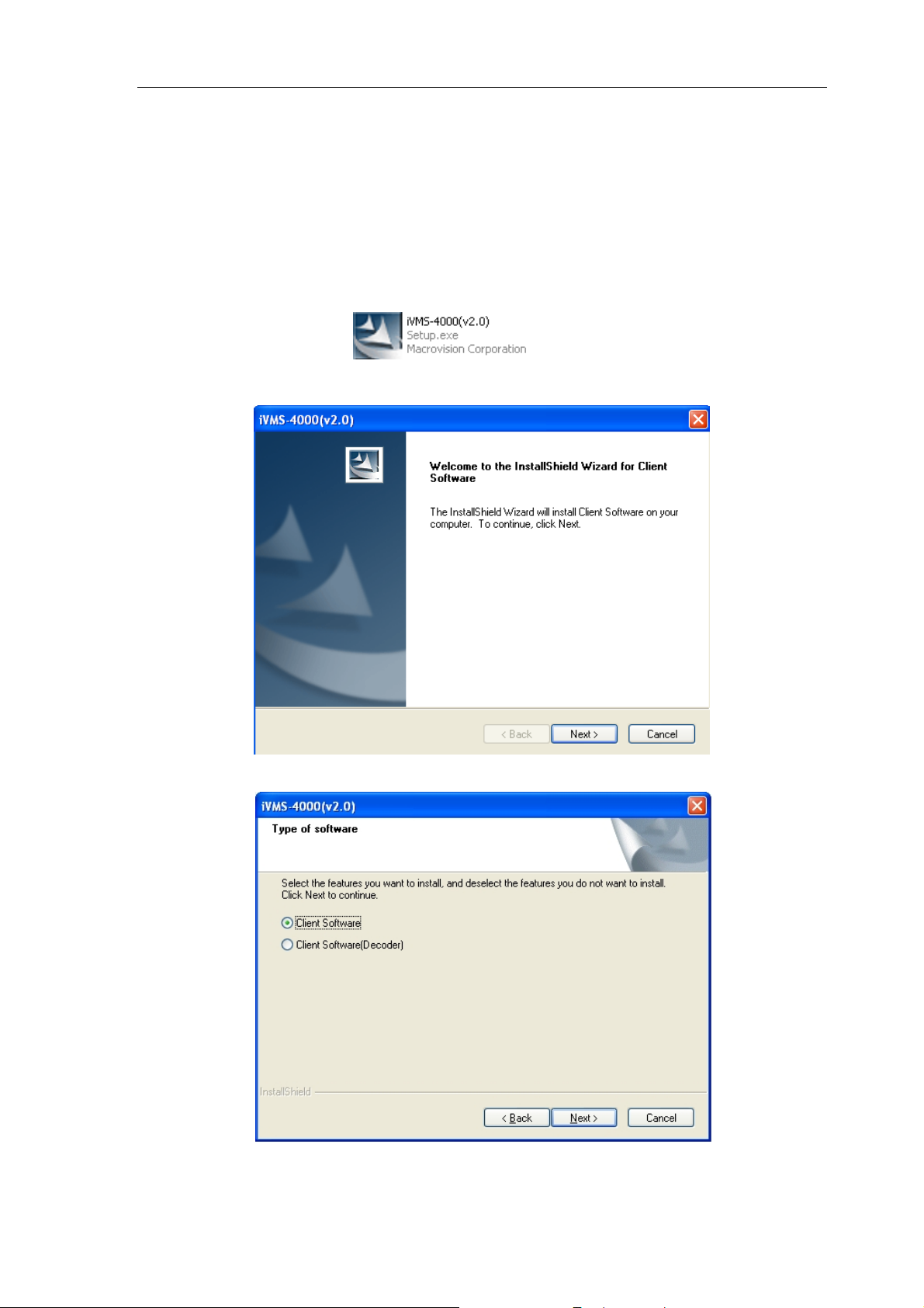
2.1 Install the Software
Double click the program file to enter the following InstallShield Wizard as
shown below:
Click “Next” to enter the next step. Select “Client Software” option and then click “Next” again.
5
Page 7
User Manual of iVMS-4000(V2.03)
Input the user information and so
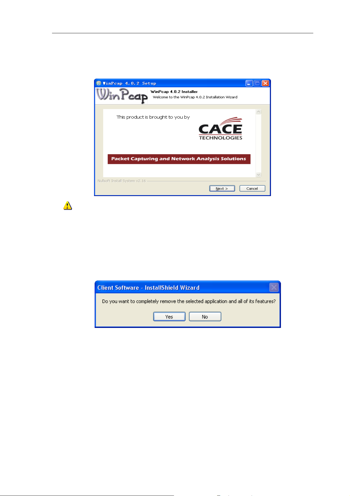
After that, a SADP installation wizard will pop up; click “Next” to start to install WinPcap. If it has already
been installed, this step can be cancelled.
Note: SADP is used as the on-line device finder; this function is unavailable if the WinPcap is not
installed.
ftware installation location according to the hints.
2.2 Uninstall Software
Enter start menu, select “All programs””iVMS-4000(v2.0)””Uninstall iVMS”, and the InstallShield Wizard
shown as below will pop up:
Click “Yes” and start to uninstall the software, the un-installation will finish after the computer has restarted.
6
Page 8
User Manual of iVMS-4000(V2.03)
Chapter 3 Basic Operations
Click “Start””All Programs””iVMS-4000(v2.0)”” iVMS-4000(v2.0)” to start the software.
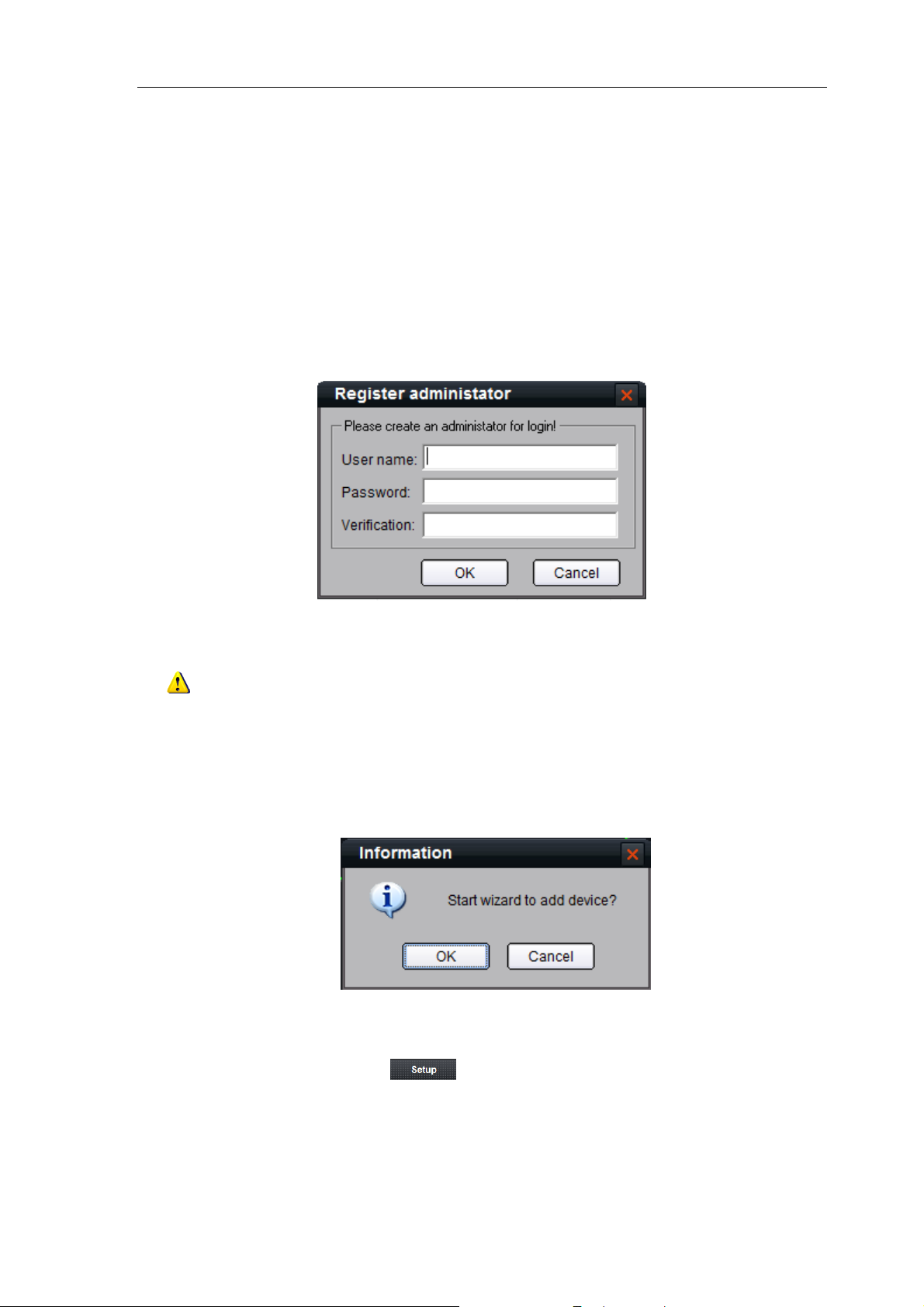
3.1. User Registration
User needs to register an administrator if the iVMS software is used for the first time.
Input the user name and password in the dialog box and click “OK”. Then, user can log in as the
administrator.
Note: Enter, Space, and TAB buttons are invalid for the user name and password. The password cannot
be null, and should not contain the following characters, including “%” and “’”. Password should not be less than
six characters and does not support the copy and paste operation.
Add Device Wizard
After registration and login, the following information will pop up:
Click “OK” to start the wizard and add the device, or click “Cancel” to exit the wizard.
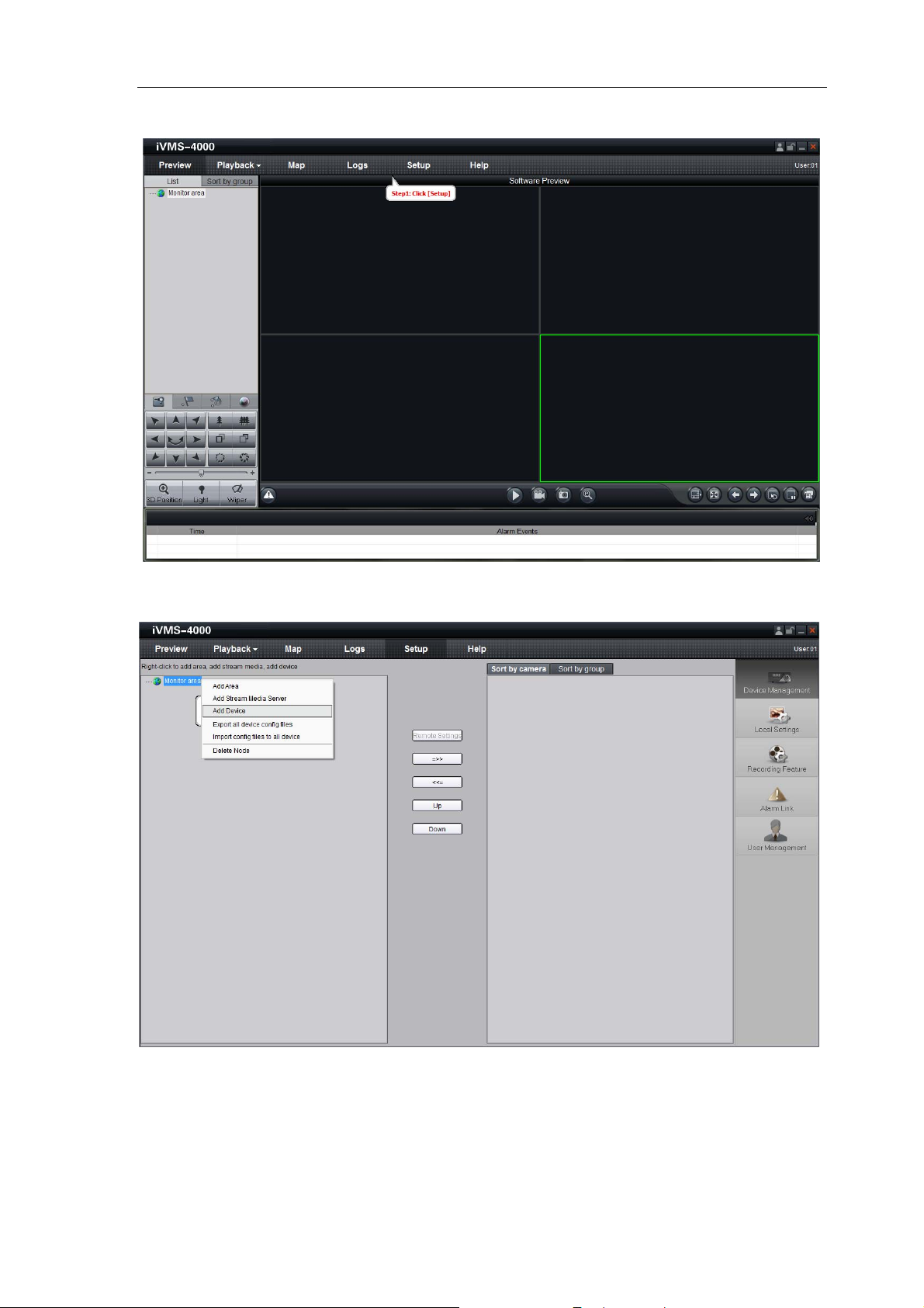
st
1
step: According to the hint, click to enter the device adding interface.
7
Page 9
User Manual of iVMS-4000(V2.03)
nd
step: According to the hint, right click on the default area node and then select Add Device option from
2
the right-click menu to add a device.
8
Page 10
User Manual of iVMS-4000(V2.03)
Ent
er the device information in the text box of
Add Device interface.
Please refer to
details.
Section 4.2 Add Device
for more
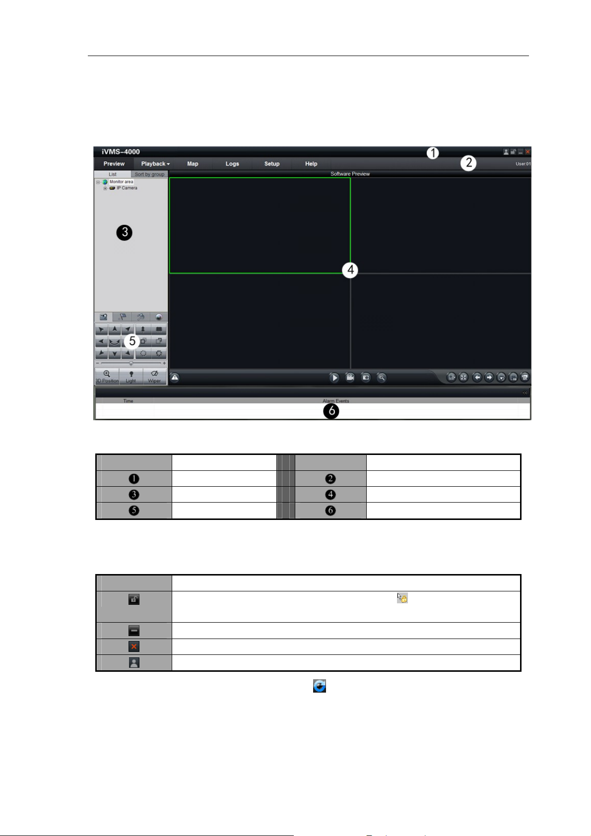
3.2 User Login
When user opens the iVMS software after registration, the login dialog box will pop up, shown as below:
Input user name and password, and then click “Login” to start using the iVMS software.
Click
input them again for future login.
If user wants to change password, please select a user name and click “Modify”.
If the user name or password is incorrect, the following warning information will pop up:
If user wants to cancel login, please click “Quit”.
Note: Please stop all the operations (e.g. preview, recording, playback and etc.) before switching the
users.
to automatically save the user name and password, then user does not need to
9
Page 11
User Manual of iVMS-4000(V2.03)
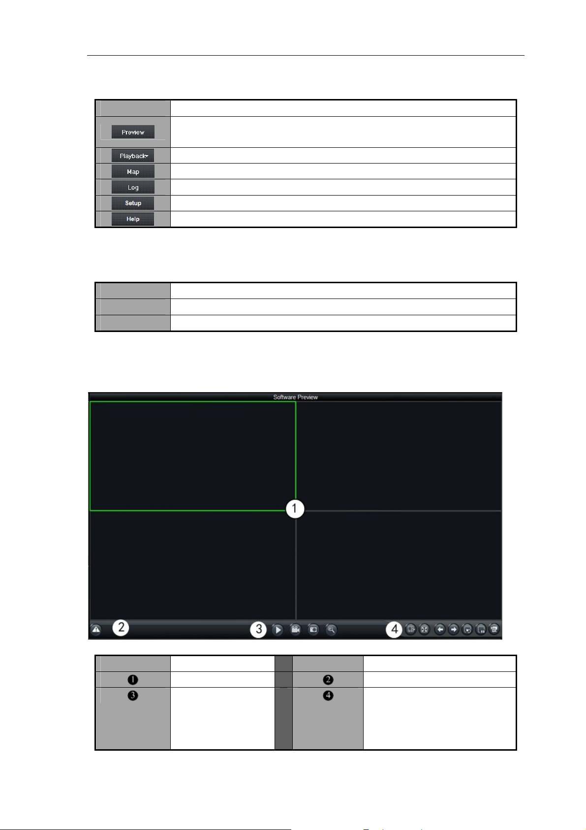
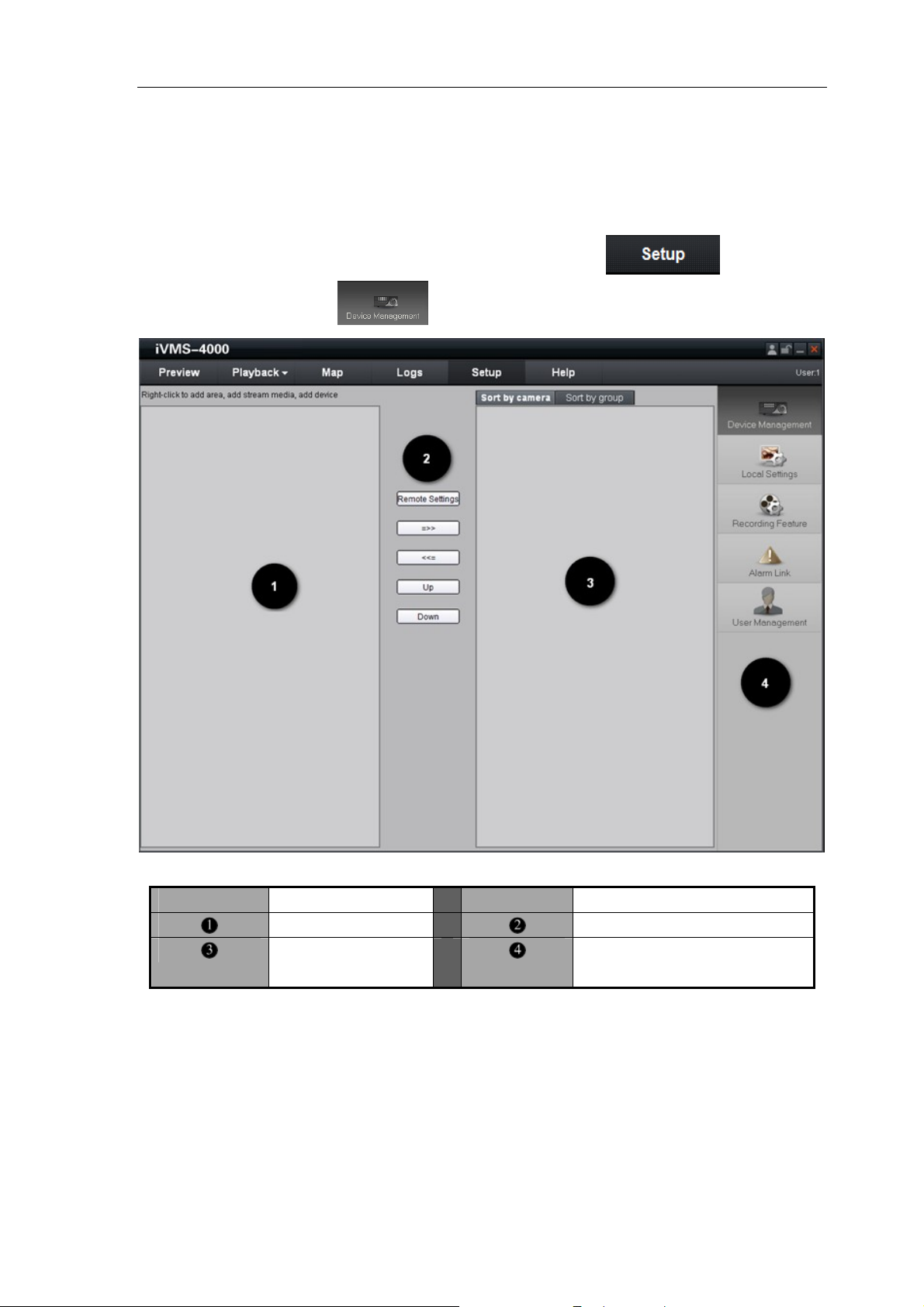
3.3 GUI Introduction
The main interface of the client software is described as below:
System Panel:
Area Description Area Description
Toolbar
Device Area
PTZ Control Area
Menu Bar
Preview Area
Alarm Info Area
Toolbar:
Button Description
Minimize the iVMS software and right click the icon “ ” on the taskbar, then you’ll see the popup menu
luding software/hardware preview, setup, remote VOD, local playback, map, log and exit options.
inc
Lock button. When user clicks it, the icon will change to
window and input the correct password to unlock the interface.
Minimize button
Exit button
Software user switch button
; re-click it to activate login
10
Page 12
User Manual of iVMS-4000(V2.03)
Menu Bar:
Area Description
Enter preview interface (If the deco is installed in PC, then enter the ding card
Enter playback interface, including remote VOD and local playback
software or hardware decoding interface)
Enter e-map interface
Enter log query interface
Enter setup interface
Enter Help (user manual) tware info) menu and About (sof
evice Area: D
Mode Description
List Display by list
Sort by group Display by group
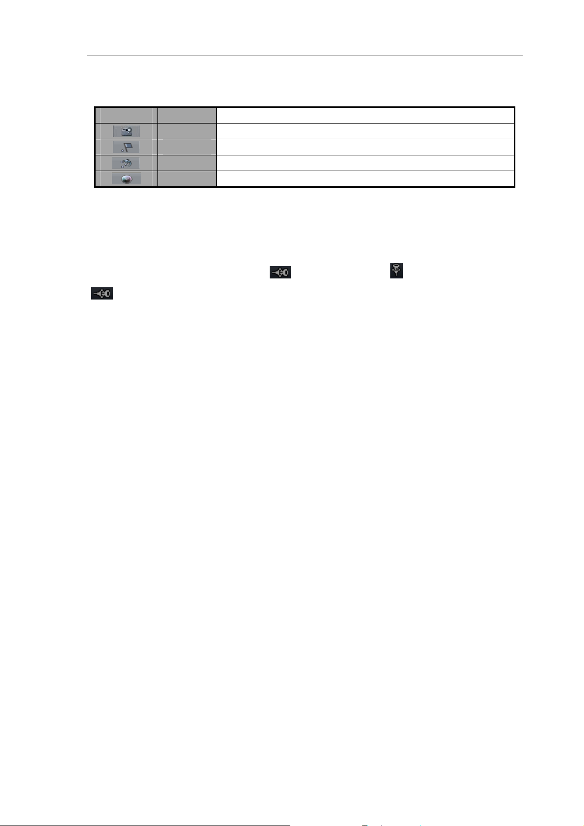
review Area: P
Area Description Area Description
Dis
Basic functional
capture and digital
zoom
s play window
dbut , tons: play, recor
window
up,
11
Alarm indi cator
Advanced functional buttons:
division, full screen, page
page down, resume cycle, pause
cycle and show channel state.
Page 13
User Manual of iVMS-4000(V2.03)
PTZ Control Area:
Icon Options Description
PTZ Control PTZ
Presets Configure and call the preset
S Configure sequence
equence and call the
V Brightness, contrast, saturation, djustment ideo hue and volume a
Alarm Info Area:
Display alarm time, information and alarm sign. The area size can be enlarged by dragging the upside of the
ea. You can fix the ar ; and when it returns to
“ ”, the area size will resume to original size.
ea size by clicking icon , which will then turn to“
“
”ar
”
12
Page 14
User Manual of iVMS-4000(V2.03)
Chapter 4 Device Management
Before any operations, user needs to add device and configure it. Click to enter the
configure mode, and then click
to manage the device.
Area Description Area Description
List area
Group/Shortcut key
area
Configuration buttons
Navigation bar
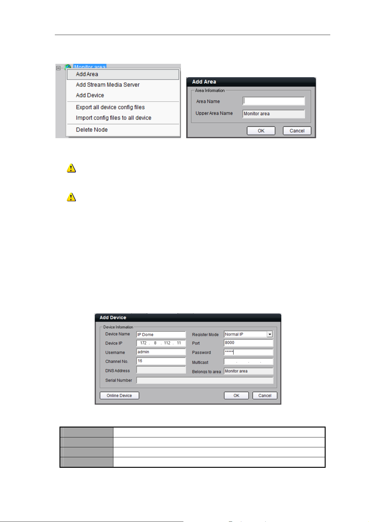
4.1 Sub-area Configuration
By default, the system has the root area named as “Monitor Area”. User can right click it to add the sub-area.
Select “Add Area” from the menu to enter the Add Area dialog box, as shown in the following figure:
13
Page 15
User Manual of iVMS-4000(V2.03)
Enter the area name and then click “OK” to save the settings. The new sub-area will be displayed under the site
tree.
Note: Enter, Space, TAB is invalid in the area name. It cannot be null and should not contain the
following characters, including “%” and “’”.
Note: When you select “Delete Node”, the sub areas, stream media servers, and devices under the root
of this area will be deleted as well. Before doing that, you need to stop current preview or recording, otherwise
there will be warning information popping up.
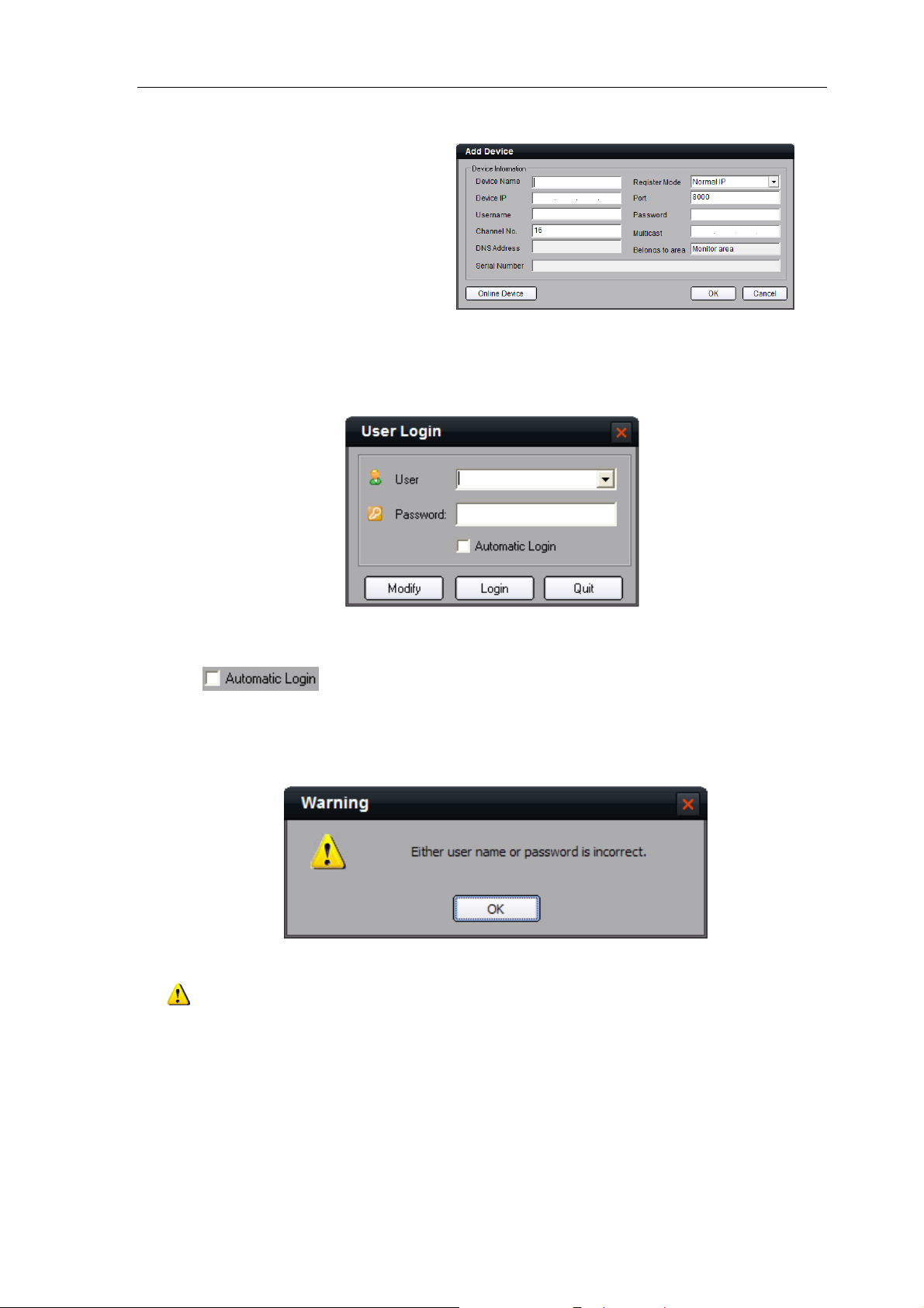
4.2 Add Device
Right click the area and select “Add Device” to enter the Add Device dialog box. Enter the information of
device to be added.
Normal IP mode
The default register mode is the “Normal IP”. After input the device name, IP address, username, password,
port and channel No. Click the “OK” button to finish adding device.
The Illustration about the adding interface:
Options Description
Device Name User-defined
Register Mode Normal IP, Private Domain, Normal Domain
Device IP IP address of the device
14
Page 16
User Manual of iVMS-4000(V2.03)
Port Device port (default: 8000)
User Name User name of the device (default: admin)
Password Password of the device (default: 12345)
Channel No. The channel number of the device
Multicast Used when visiting the device by the way of multicast, or else leave it blank
DNS Address
Belong to area Display the area to which the current device belongs
Device serial Used when adopting private domain, or else leave it blank
Used as IP address of IP server when adopting private domain, or else it can’t be
filled.
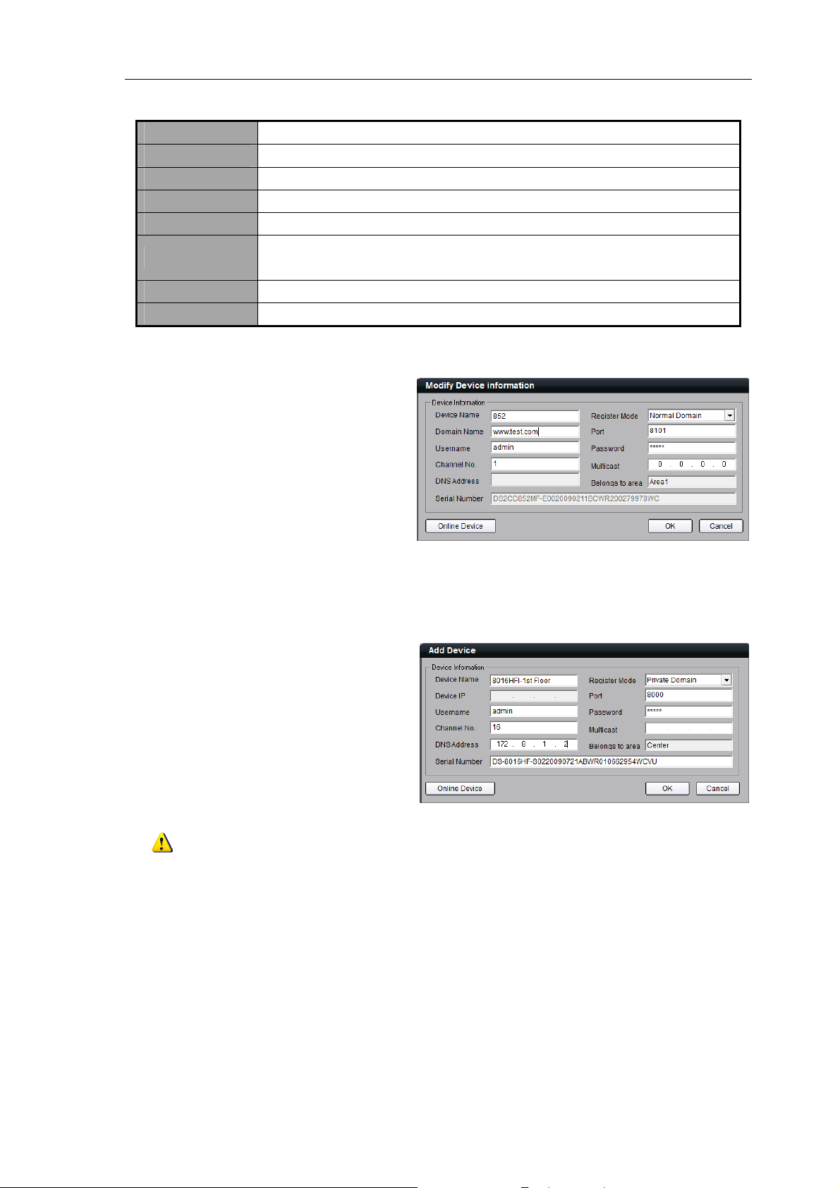
Normal domain mode
If you select normal domain,
please enter the domain name with
the registered domain name in the
text box.
Private domain: If you configure the device with the address of IP Server that runs normally, then the
connected device can be resolved by IP Server; and iVMS software can get the dynamic IP address from IP Server
by server name or by serial number.
Private domain mode
If you select private domain, please
input the correct device serial number
and IP address of IP server in the text
box of DNS Address.
Note: In private domain mode, if you input device serial number, the iVMS software will go to obtain
the IP address from IP server; If no device serial number is entered, the IP address can be obtained by using
device name to resolve IP server, yet the device name you enter here must be the same with the name in the
device.
Click “OK” to finish adding device.
Right-click menu is available,
double click the node can modify the
device parameters. If the device is not
online or not connectable, some options
are not invalid.
15
Page 17
User Manual of iVMS-4000(V2.03)
Note: Up to 50 devices can be added.
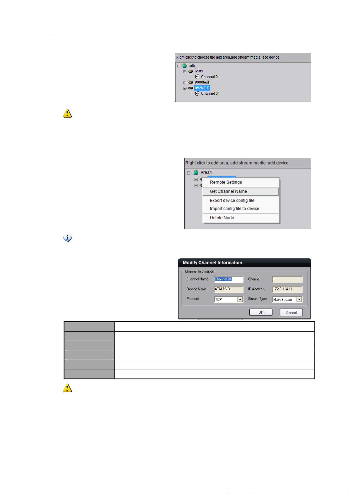
4.3 Channel Configuration
Click “Get Channel Name” to get
the names of all channels.
Tips: The main stream is usually used for device encoding, which sub stream is for network
transmission.
Double click the channel name and
then the “Modify Channel Information”
dialog box will pop up.
Channel Name Current channel name, editable
Channel Channel number of the device, unchangeable
Device Name Device name, unchangeable
IP Address Device IP address that unchangeable
Protocol Select connection protocol: TCP, UTP, MCAST and RTP.
Stream Type Choose main or sub stream for the channel
Note: If the option “Get channel name” is selected, the channel name will be replaced with the name
saved in the device.
4.4 Channel Configuration of DS-9000 Series DVR
DS-9000 Series DVR supports the preview and recording of IP camera, IP dome and DVS. When the DS-9000
16
Page 18
User Manual of iVMS-4000(V2.03)
eries DVR is added to iVMS software, then it is accessible to add and manage the IP channels as well as to
S
enable or disable the analog channels.
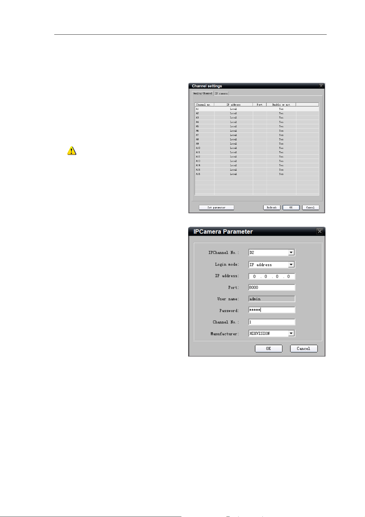
Right click the device name and
select “Remote Configuration”, then the
“Channel Configure” menu will pop up.
The “Analog Camera” will show by default.
Double click the selected analog
channel to enable or disable it.
Note: DS-9000 series DVR can not
preview and record this channel when it is
disabled, unless it is enabled again.
Click “IP camera” to enter the
interface of IP channel management.
Click “Add” to add IP channel.
Input the IP address, user name,
password and port, and then click “OK”.
17
Page 19
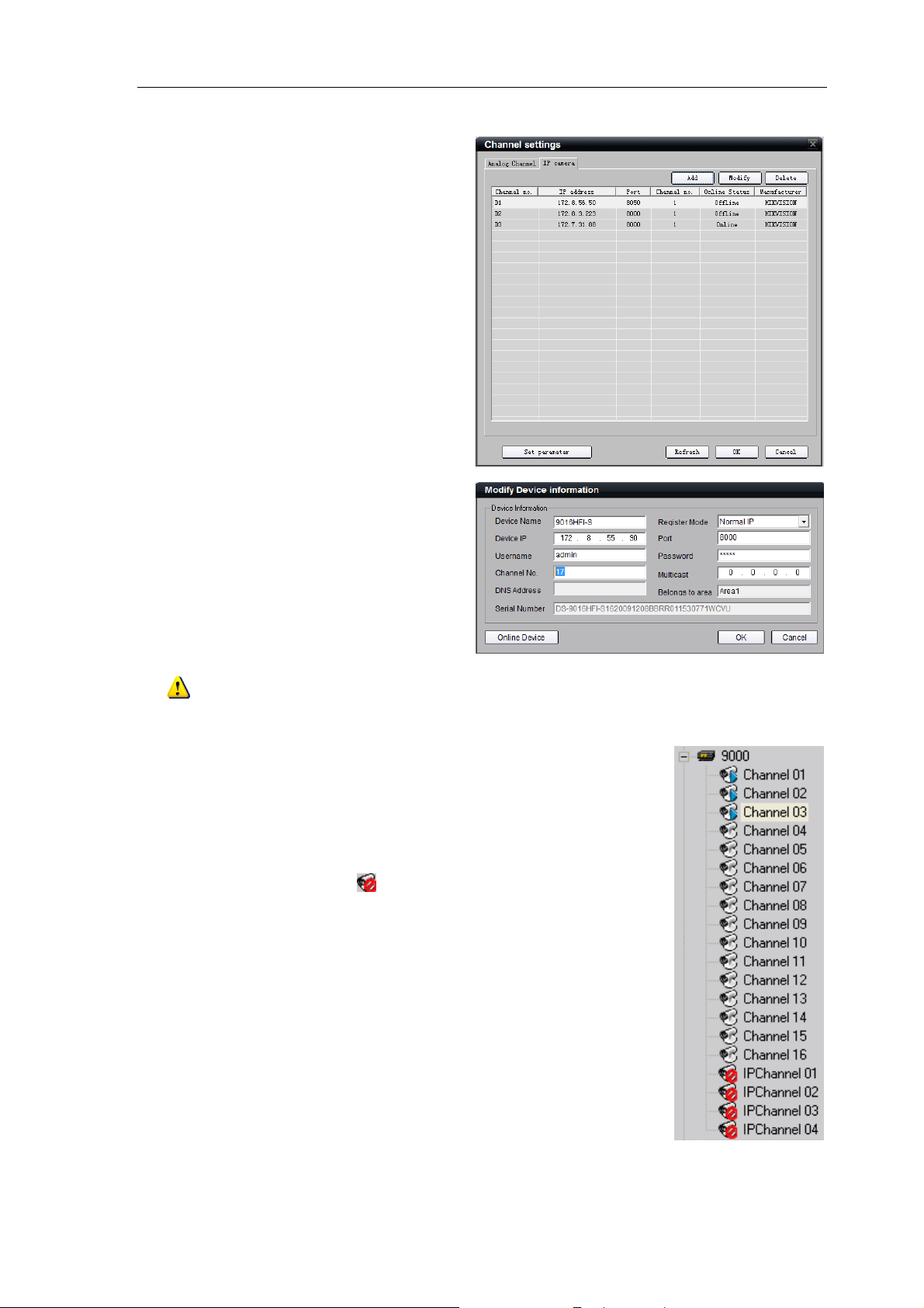
Double click the selected channel
to modify the parameters.
Click
“Delete” to delete the selected
channel.
After that, you can change the
channel number according to the added
channels. Double click the device name
to modify the device information.
User Manual of iVMS-4000(V2.03)
Note: DS- 9016HFI-S DVR supports up to 16 analog channels and 8-ch IP cameras to be added. Please
refer to the user manual of DS-9016HFI-S for more details.
After that, the added IP channel will be seen in the channel
list of the device.
If IP channel cannot be connected, the icon under the
preview interface will be shown as
18
Page 20
User Manual of iVMS-4000(V2.03)
4.5 Stream Media Server Configuration
When the connections is up to the limit of the device or the bandwidth is not enough, user can add the
stream media server to forward real-time video stream, then it can reduce the pressure of the device network.
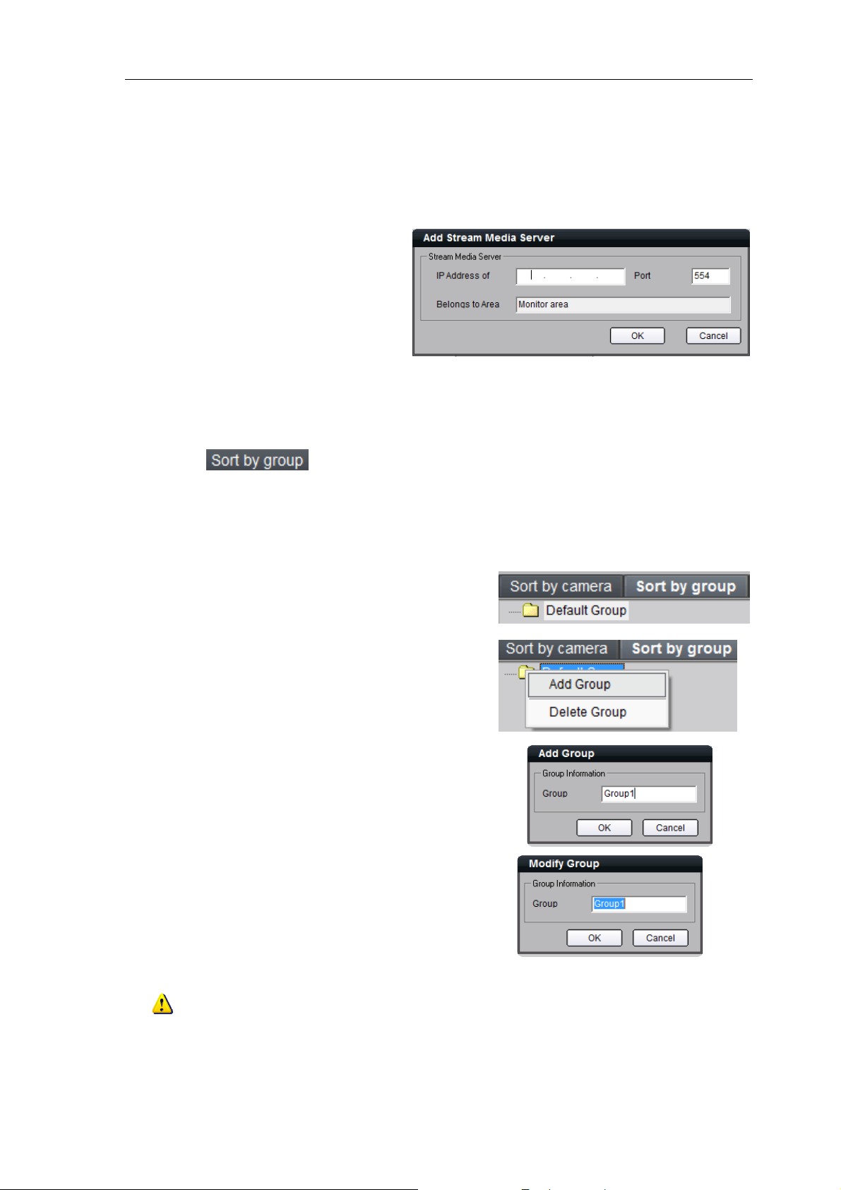
Right click the Area node, select
the “Add Stream Media Server” option,
input the IP address and the Port (554
as default, need to be the same as
stream media server setting), then click
OK to finish.
4.6 Group Configuration
Click the button to enter group area management window.
4.6.1 Sort by group
There is the default group. You can
add new channels or delete the existed
channels.
Right click in the empty area and
you will see sub menu as shown on the
right.
S
elect “Add Group”.
Input the group name and click
“
”
Double click the group name to change the group
name.
Right click the group name and select “Delete
Group” to delete the selected group.
Note: Enter, Space, TAB is invalid in the group name, which cannot be null, and should not contain the
following characters, including “%” and “’”.
19
Page 21
User Manual of iVMS-4000(V2.03)
4.6.2 Channel
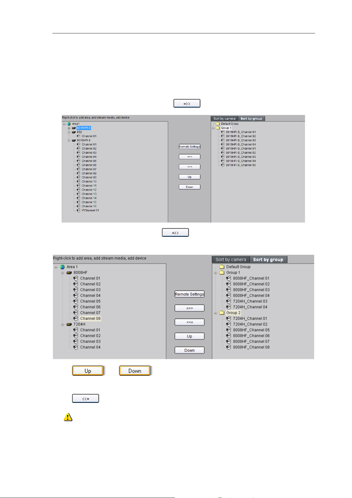
After adding the group, the channels in the site tree can be moved to the selected group.
Add Channel
Select the channel from the site tree, and click key to move it to the selected group.
Select the device in the list area and click
to the selected group.
Use
and keys to adjust the channel sequence in the group list.
Delete Channel
key and all the channels of the device can be moved
Use key to delete the channel or group in the group area.
Note: One channel can be added to different groups, yet one group cannot add the same channel
repeatedly. Max. 50 different channels can be added to one group.
20
Page 22
User Manual of iVMS-4000(V2.03)
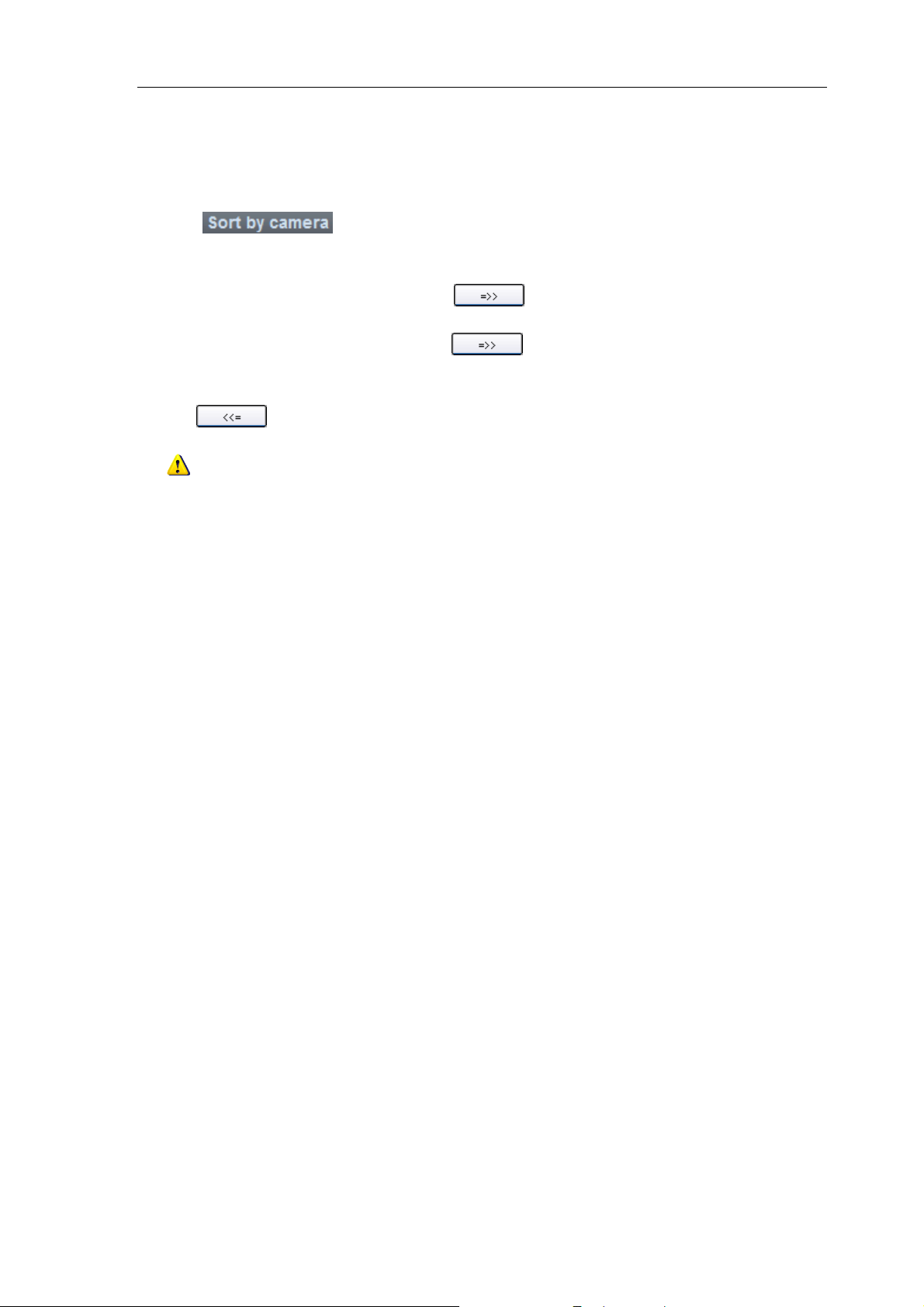
4.7 Sort by Camera Configuration
Click button to enter shortcut key management window. Only the channels can be
added to the “Sort by camera” area.
Select the channel from the list area, and click
Select the device from the list area, and click
sort by camera area.
Use key to delete the channel in the sort by camera area.
Note: Up to 256 channels can be added to “Sort by camera” area.
key and move it to the “Sort by camera” area.
key to add all the channels of the device to the
21
Page 23
User Manual of iVMS-4000(V2.03)
Chapter 5 Preview
After configuring the device, click the key to return to the preview interface. Click the “List”
and “Group” keys to switch between two modes.
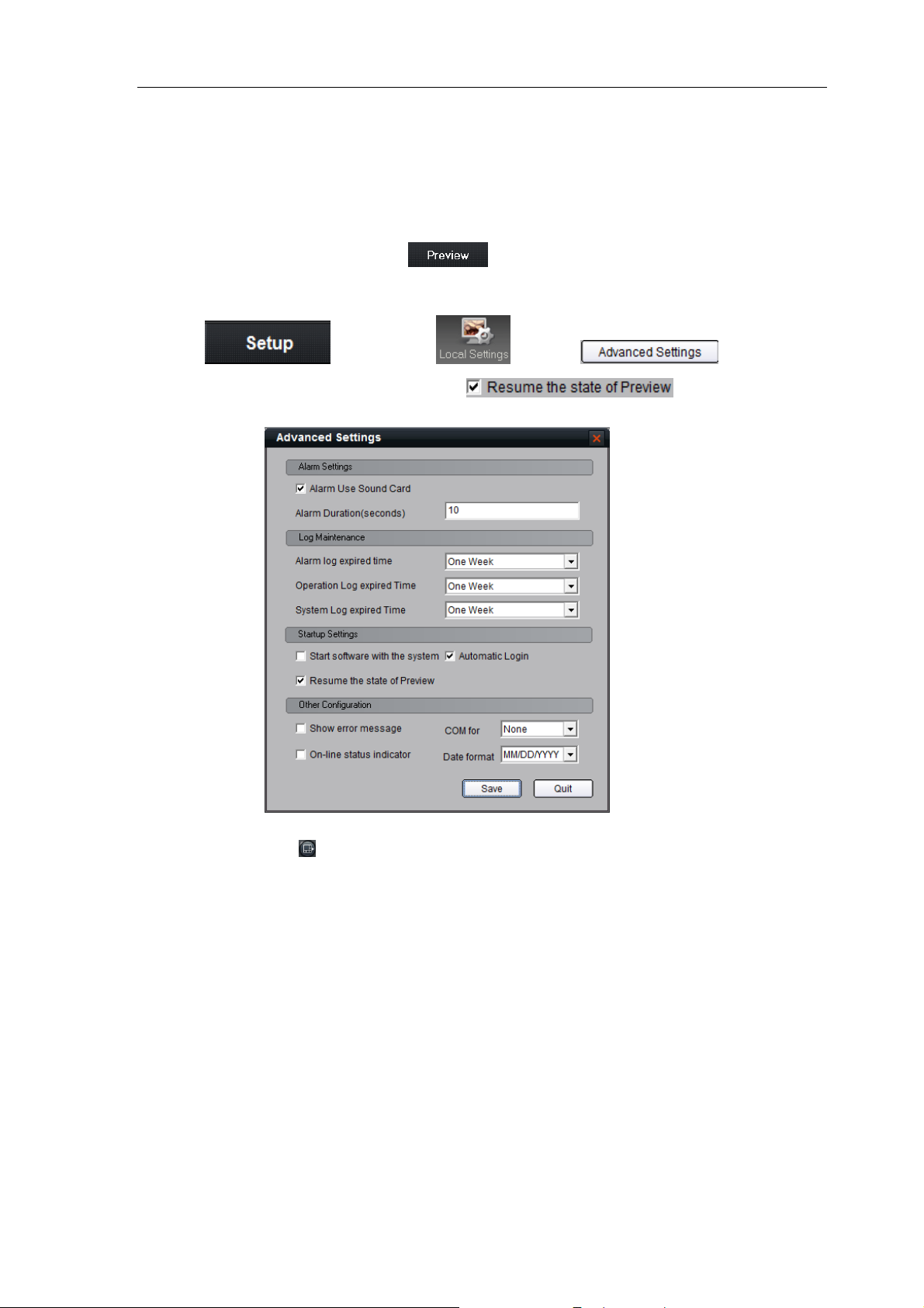
Click
“Advanced Settings” in which user can enable the
preview state including window division and preview channel for next login.
The play windows are divided into 2×2 mode as default, and up to 64 window divisions can be conf igured.
User can click the button
key and then key and button to enter
option to save current
to change window division mode.
22
Page 24
User Manual of iVMS-4000(V2.03)
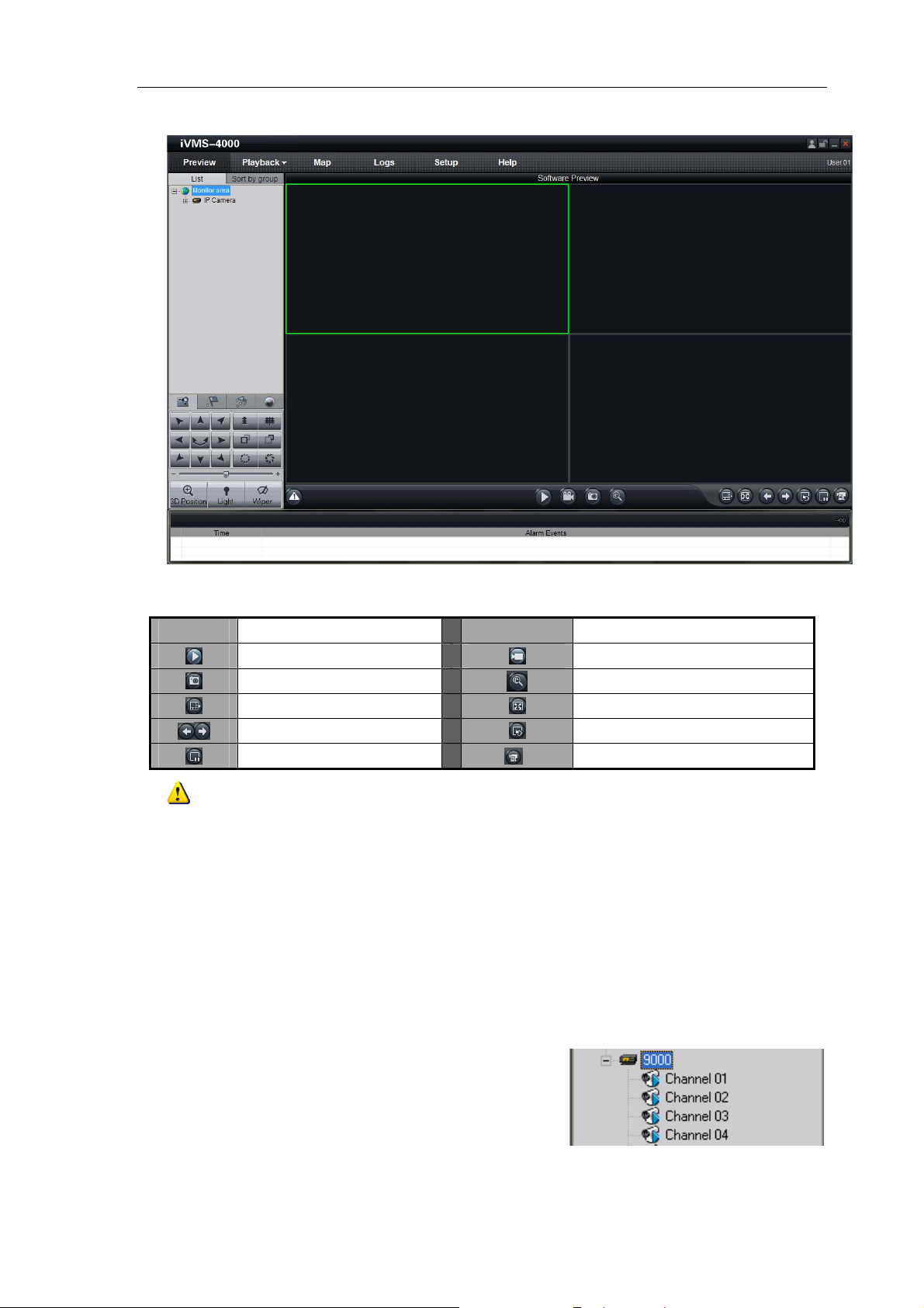
Preview Panel Buttons:
Area Description Area Description
Note: The window division mode and channel sequence can be remembered by the Client Software as,
and will play automatically when log in next time.
Page up, page down
Stop cycling all the device
Play
Capture
Window division
Resume cycling all the device
Record
Digital zoom
Full screen
Show channel state
5.1 Non-cycle Preview
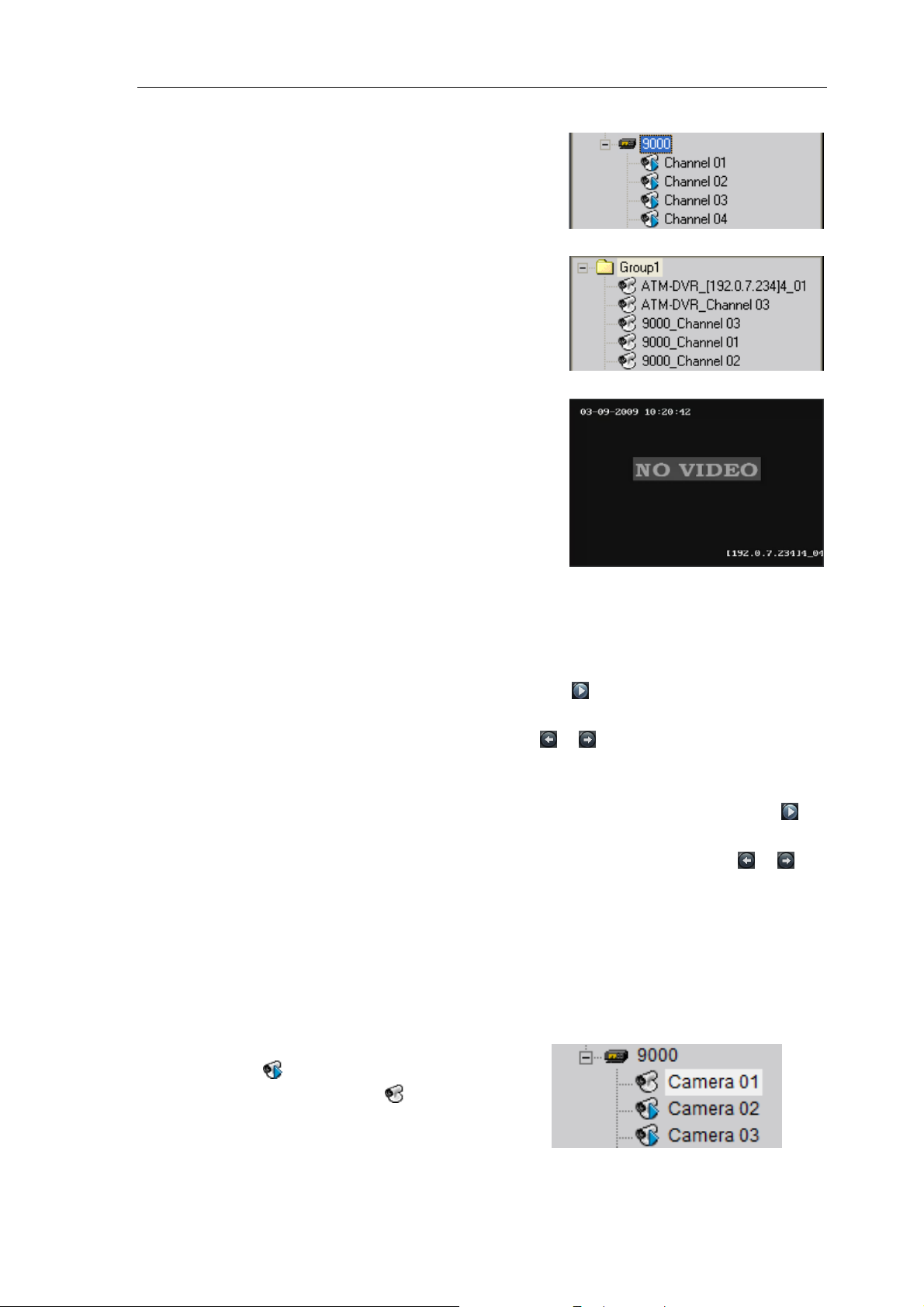
5.1.1 Play by Node
Double click the device name or drag it to the play window to preview (cycle preview disabled).
Double click the channel name to preview the
corresponding cameras.
23
Page 25
User Manual of iVMS-4000(V2.03)
Double click the device name to preview the
corresponding cameras of the device in the current
window divisions.
Double click the group name to preview the
corresponding cameras of the group in the current
window divisions.
You can also preview them by dragging them to the
play windows.
5.1.2 Sort by Camera Preview
Sort by camera mode
If it has configured “Sort by camera” in the device list, then press “ ” button of the preview interface to
view all the corresponding channels in the “Sort by camera” area in the current window divisions. If the channel
number is more than the window division number, user can click
Please refer to the
Section 4.7 Sort by camera Configuration
for more details.
and to change the page to preview.
Sort by group mode
Click the “Sort by group” to enter this mode. If the “Sort by group” has been configured, then press “ ”
button of the preview interface to view all the corresponding channels in the Sort by group area in the current
window divisions. If the channel number is more than the window division number, user can click
change the page to preview. Please refer to the
Section 4.6.1 Sort by Group Configuration
for more details.
and to
5.1.3 Stop Playing
There are 3 ways to stop live preview.
Double click the channel to stop playing.
The play icon is , double click it to stop previewing
this channel and the icon will change to
.
24
Page 26
User Manual of iVMS-4000(V2.03)
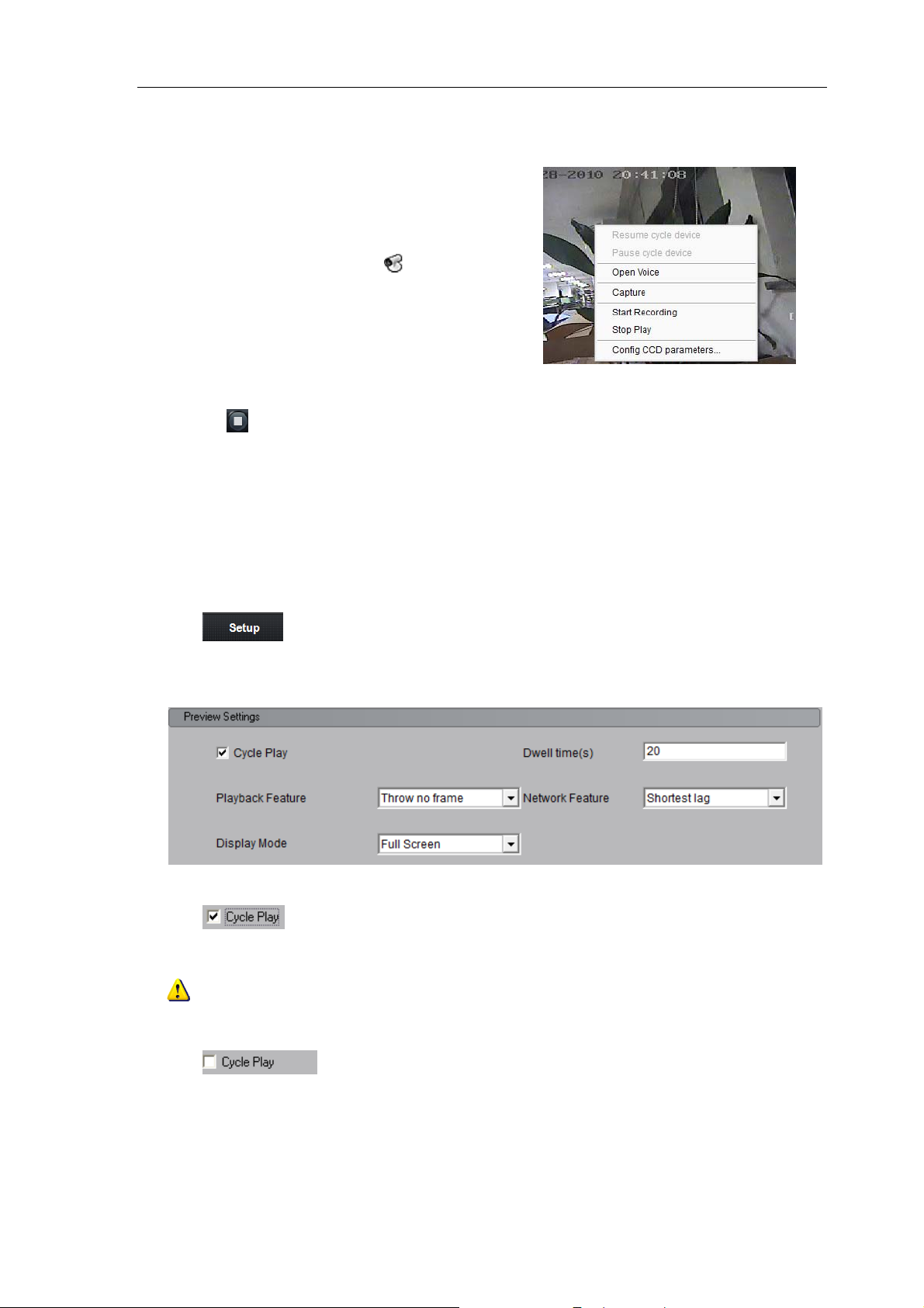
Right click video to stop playing
Right click in the play window and the menu will
pop up. Click “Stop Play” and the live view will stop.
Meanwhile, the play icon will change to
.
Stop all playing
Click the key in the preview panel to stop all the live view channels.
5.2 Cycle Play
5.2.1 Cycle Configuration
Click key to enter the configuration interface. Then enter the local settings interface by click
“Local Settings” button.
Enable Cycle:
Click to enable Cycle Play, and input the cycle time. Click “Save” and return to the preview
interface.
Note: The cycle time should be set between 20 and 300s.
Disable Cycle:
Click
to disable Cycle Play and save the settings.
25
Page 27
User Manual of iVMS-4000(V2.03)
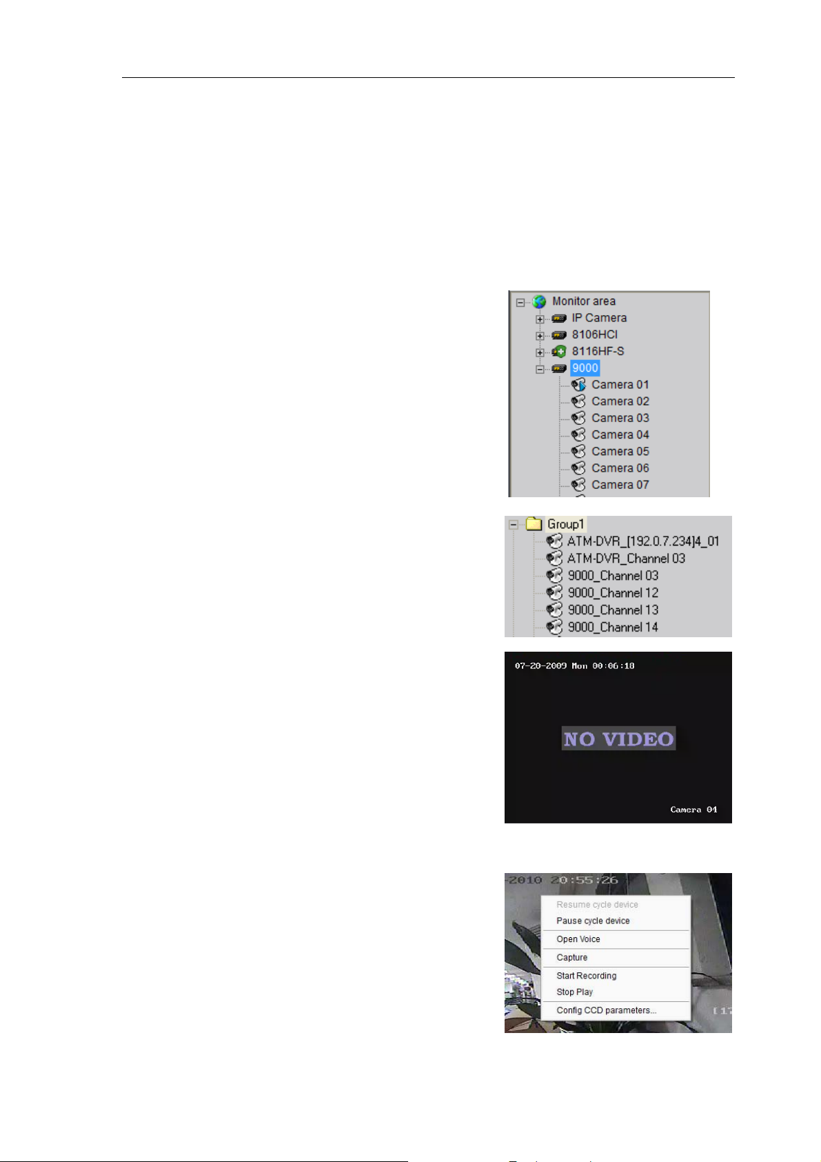
5.2.2 Cycle Play of Device/Group
Start cycle
Double click the device name and all the channels of
the device begin to cycle in the selected window division
from the 1st channel.
Double click the group name and all the channels of
the group begin to cycle in the selected window division
from the 1
then all the channels of this device begin to cycle.
all the channels of this group begin to cycle.
st
channel.
Drag the node of the device to the window, and
Drag the node of the group to the window, and then
Pause/Resume Cycle
If the current window is in the device/group cycle
mode, right click the cycling window, click “Pause cycle
device” or “Stop cycle group” to pause cycling and
remain the current image.
26
Page 28
User Manual of iVMS-4000(V2.03)
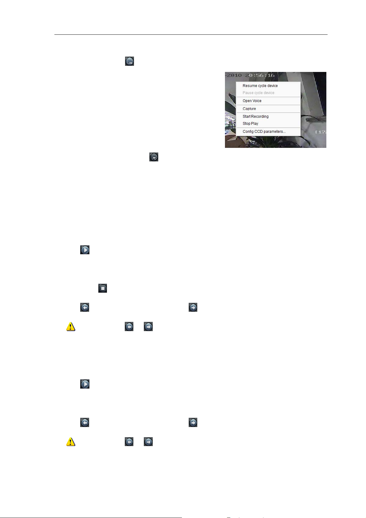
ause cycle” key
Click “P
If the current window is in the device/group cycle
mode, right click the paused window, click “Resume cycle
device” to restart cycling.
to pause all the cycling window divisions.
Click “Resume cycle devices” key
to restart all the paused channels.
5.2.3 Mixed Cycle
Mixed cycle mode enables iVMS software cycle previews channels of the group or sort by camera, the
default window division is 2×2.
Cycle Play of Sort by camera Channels
Click “List” key to display channel list.
Click
short key area, then start cycle playing, the first 4 channels will be displayed in the window, after one cycle
period, the last 4 channels will be displayed in the window.
Click button
Click
key to start mixed cycle play. Take 2×2 window division for example, if there are 8 channels in the
in the preview panel to stop the channel mixed cycle of short key.
key to display the first 4 channels, click key to display the last 4 channels.
Note: Click button or to pause the channel sequence cycle of sort by camera. This function
needs sort by camera configuration first.
Cycle Play of Group Channels
Click “Sort by group” key to display group channel list. (Please stop playing before switching to group
channels.)
Click
by group area, each of them has 4 channels, then start cycle playing, 4 channels of the first group will be
displayed in the window, after one cycle period, 4 channels of the second group will be displayed in the window.
Click
needs sort by group configuration f irst.
key to start mixed cycle play. Take 2×2 window division for example, if there are 2 groups in sort
key to display the first 4 channels, click key to display the last 4 channels.
Note: Click button or to pause the channel sequence cycle of sort by group. This function
27
Page 29
User Manual of iVMS-4000(V2.03)
5.3 Preview Control
Full Screen:
In preview mode, user can click key to preview in full screen.
Enlarge:
When in the multi-screen preview mode, double click the selected image to enlarge it, and double click
again to resume.
If user is previewing the zero-channel, double click it first time, it will enlarge the zero-channel, double click
on window division in the zero-channel video, it will enlarge that channel to fill the zero-channel video. Double
click it the third time, it will only change the zero-channel form single to multi display.
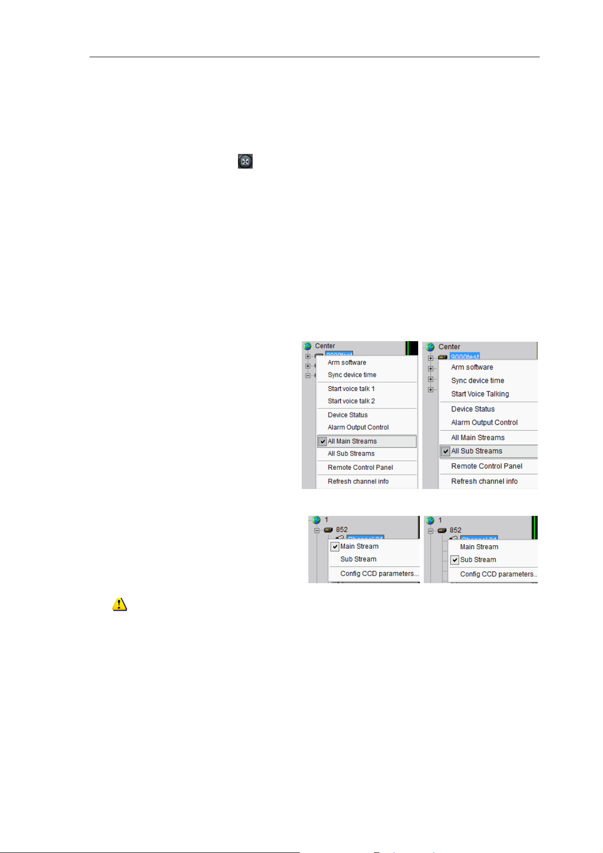
Main/Sub Stream:
Main stream is for recording, sub stream is for network transmission when bandwidth is low. The stream will
take effect after re-preview the device or channels.
Software use the main stream by default, if needed, user can switch to sub stream to preview.
Right click device name and select “All Main
Streams” or “All Sub Streams” to change the device
Right click channel name and select “Main
Streams” or “Sub Streams” to change the channel
stream type.
Note: the sub stream preview needs the device to support, or else the sub stream preview will be
failed.
28
Page 30
User Manual of iVMS-4000(V2.03)
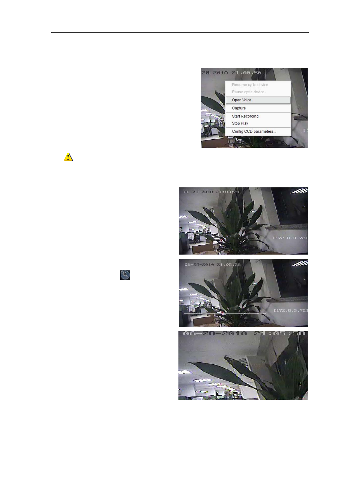
Voice Control
Right click the selected window, select “Open Voice”
to enable audio preview, right click again and select
“Close Voice” to disable audio preview.
Note: The software only can open voice of one window at the same time. If the voice of the next
window is opened then the voice of the previous will be closed automatically.
Digital Zoom
Software support digital zoom function
Select a window, click , hold on the left
button of the mouse, drag the mouse to the
right and down direction.
Release the mouse, it will display the zoom
area.
Hold on the
it will return to the full of the video sense.
left button and drag to the left,
29
Page 31

User Manual of iVMS-4000(V2.03)
Channel State
In preview mode, click the button to
enable the display of the current channel state.
And then the icon will change to , which can
be selected to hide the channel state.
The icons shown on the title bar are
described as below:
No local recording/local recording
Normal signal/signal loss
Normal hardware/abnormal
hardware
Current bitrate level (1~5)
5.4 Two Screen Preview
If the computer has connected two
monitor and opened, there will be
button on the top of it.
Click this button, pop up the pull-down
menu, including ”AUX screen
preview”, ”Electronic map” and ”Remote
VOD”
Click “AUX screen preview”, the second monitor will display the preview window.
The aux screen operation is the same as the main screen, refer to the former chapters.
Note: when the main screen is the 64 divisions, the aux screen can’t be opened. After opened the aux
30
Page 32

User Manual of iVMS-4000(V2.03)
een, they both max support 32 window divisions.
scr
5.5 Recording & Capture
Recording and capture is only available in the live view mode.
Note: If the channel is in the recording mode, click “Stop” button to stop recording, and the preview,
cycle play are stopped as well.
5.5.1 Recording
Record Disk Configuration
Click to enter the Local
Recording Settings interface:
Select the saving hard disk of recorded files in “Store setup”.
Instant Recording
When previewing, click the button to start recording, and the icon changes to , and the channel icon
changes to . Click the button to stop recording.
After recording, the hint window with index of
recorded files will pop up; click the hint to open the target
31
Page 33

User Manual of iVMS-4000(V2.03)
5.5.2 Capture
Click to enter the Local Settings interface.
Image format configuration
Format Selection Instruction
Resolution and image quality can be changed.
JPEG
BMP
If capture the IP camera with higher
resolution, please uncheck it.
Resolution and image quality can’t be
changed, capture depending on current
channel parameter
Path configuration
The default saving path is
change the saving path.
C:\Program Data\Client\Picture
Capture
In preview mode, click the button to start capture.
After picture captured, the hint window with capture index
will pop up; click the hint to open the target folder.
. User may click the button to
32
Page 34

User Manual of iVMS-4000(V2.03)
5.6 Hardware Decode
If there is video/audio decoding card installed in the computer, then this function can be available.
5.6.1 Hardware Decode Configuration
Before hardware decode on TV Wall, user needs to configure the card output and window division mode, or
else it will use the default decode mode.
Click
The decoding card installed in the PC can be recognized and initialized automatically as iVMS software
starts up, and the information will be displayed in the decoding card info area. The icon
output of the decoding card will be used to duplicating by the icon.
key and then on the right to enter the configuration interface
means which video
The area descriptions are as follows:
Area Instruction
Configuration Area: 2 options including Video Output Standard & Decode Mode.
Decoding Card Info Area: Show the information of the decoding cards and channels.
Output Window Area: Configure the output mode of decoding channels.
Window Division Mode Select Area: Select window division mode.
33
Page 35

User Manual of iVMS-4000(V2.03)
5.6.2 Hardware Decode Mode Configuration
4000MDI decode card has two output standard: PAL & NTSC.
The decode mode: ”Factory default”, ”Preview On, TV Wall On”
and ”Preview Off, TV Wall On”.
Consumption Mode: Enable the consumption mode to decode
the video stream of 73/8100 and 90/9100 series device, if the
resolution is D1, the decoding channel halve.
Other ins
Decode Mode Descriptions
Factory Default
TV wall on & Preview on
TV wall on & Preview off
truction as below:
Each 4002MDI card decodes 2 channels; each 4004MDI card decodes 4
channels and so on. Support decoding and cycling play.
The images from the play window of iVMS software and TV wall are
decoded by MDI card, which needs to configure in the hardware decode
configuration.
The images from the TV wall are decoded by MDI card; the images from the
play window of iVMS software are decoded by CPU.
If the resolution of all the images is CIF, then the max decoding channel number is: 4 channels for each
4002MDI card, and 8 channels for 4004MDI card.
If the resolution of all the images is D1, then the max decoding channel number is: 2 channels for each
4002MDI card, and 4 channels for 4004MDI card.
Tips: Do not output more than 4 channels at CIF or 2 channels at D1 resolution from the 4002MDI card;
and do not output more than 8 channels at CIF or 4 channels at D1 resolution from the 4004MDI card.
Enable special decode mode, and enter”Setup” ”Alarm link” to set the alarm link type to “Pop up image
when alarm occurs”, which will allow the iVMS software will output the video through 4000MDI card on TV wall
when there is alarm.
Note: The video output mode of images from device and TV wall must be the same standard, or else
the video image will become abnormal.
34
Page 36

User Manual of iVMS-4000(V2.03)
5.6.3 Hardware Decode Output Window Configuration
The “output window panel” has a
multi-windo
card BNC number. One window is related to one
BNC.
Take one 4004MDI card for example, there are
4 BNCs and the “output window panel” will show
you 4 windows division. The play window is named
as 01-01, 02-01, 03-01 and 04-01.
and click the window division button to select a
window division on this BNC.
and then divide it into 4 windows, then the 4
windows will be named as 01-01, 01-02, 01-03, and
01-04.
the specified channel will be decoded and
displayed on the current window at D1
w division according to the total MDI
Select one window on “output window p
For example, if we select the first window 01-01
Tick the check box of
to , then
anel”
Note: If the default mode is selected, then each
decoding channel outputs one single image and the division
mode is invalid.
35
Page 37

User Manual of iVMS-4000(V2.03)
5.6.4 Hardware Decode Preview
After configuration, click “Preview”
key and select “Hardware Preview” to
enter the hardware decode interface.
Click to start decoding, and
meanwhile, the preview windows
layout will switch to the layout which is
set in “output window panel”.
The windo
maximum decoding channels will not
be displayed.
T
he basic operations of hardware preview are the same with the software decode. Please refer to sections
5.1-5.5 for more details.
Right click the decoding video window
division, and user can select the audio output
channel of the hard decoding card.
For example, for 4004MDI card which can
decode 8 channels at CIF resolution, the first 4
channels’ audio output can select “Open Card
1 Audio 1” and “Open Card 1 Audio 2”, and
the last 4 channels’ audio output can select
Open Card 1 Audio 3” and “Open Card 1
Audio 4”.
ws beyond the limited
36
Page 38

User Manual of iVMS-4000(V2.03)
5.6.5 Secondary Output of Hardware Decode
The MD card can output the decoded images twice. Take 4002MD card for example, one 4002MD card can
decode 4 channels CIF images, assume they are channel01, channel02, channel03, and channel04; if one
decoding channel is set as 4 divisions and separately display channel01, channel02, channel03, and channel04,
then the other decoding channel can only support one division and select one decoding channel to output the
image. The descriptions above are defined as secondary output.
Enter hardware decode config
tick the channel that set as secondary output and the
channel status will become
Click
to display secondary output list.
previous configuration information of
the secondary output channel.
in the window division
Note: The system will clear the
uration interface, and
37
Page 39

User Manual of iVMS-4000(V2.03)
5.7 Others
5.7.1 Voice Talk & Broadcast
In preview interface, right click the device name and
the sub menu will pop up.
Click
“Start Voice Talking” to talk with the selected
device.
If the device is DS-9000 DVR, then there will be two voice talk
channels for choice.
Note: Only 1 channel of voice talk is supported by the client software at the same time.
5.7.2 Audio Broadcast
38
Page 40

User Manual of iVMS-4000(V2.03)
p
Right click area name and select “Audio Broadcast”
to talk to the area.
5.7.3 Alarm Output Control
Right click the device name and the sub menu will pop
up.
Select “Alarm Output Control” to turn on or off the
alarm out
ut, and define alarm output name.
Click and it will become key, which
then allows user to enable the alarm output and activate
the name modified function. Re-click
turn off the alarm output.
key to
5.7.4 Device Status
Right click the device name and the sub menu will pop up. Click “Device Status” to get device working
information, including channel and hard disk status.
39
Page 41

User Manual of iVMS-4000(V2.03)
Note: Some options will turn gray and become unavailable if the device doesn’t support the functions.
5.7.5 Remote Control Panel
Right click the device name and the sub menu will
pop up.
Select “Remote Control Panel” and the control
panel will pop up shown as figure below.
ou can click the buttons on the panel and control
Y
device like using front panel.
40
Page 42

User Manual of iVMS-4000(V2.03)
Chapter 6 PTZ Control
6.1 RS-485 Parameters Configuration
Before PTZ operations, please make sure that RS-485 parameters has been correctly configured by iVMS
software.
Click “Setup” and enter the
esponding interface.
corr
Right click the device name and select
“Remote Configuration” from the sub
menu.
Click
to unfold the options, shown as figure on
the right.
Set right p
channel.
arameters of the each
Note: RS-485 configuration must
be the same with PTZ configuration.
6.2 PTZ Control
Return to preview interface and user can control PTZ.
There are 8 keys to control PTZ directions, and the
slide bar is used to change PTZ speed, which is
adjustable from level 1 to 7, with the default speed of 4.
Click
Click the function keys on the right to adjust focus,
iris and zoom.
key to start auto scan.
Other PTZ
Control Mode – Screen PTZ Control: user can control PTZ by dragging and click in the play
41
Page 43

User Manual of iVMS-4000(V2.03)
window
.
Drag Control: There are 3×3 nine areas, when the mouse
moves to area 1-8, the mouse icon will become as: ;
; ; ; ; ; ; , and
continued to move the mouse along the direction shown by
arrows, PTZ will move to the same directions.
Note: This function is only available for software
6.3 Partial Zoom
Click “Partial Zoom” to zoom in or out, the mouse icon will become as , press the left key of the mouse
and drag an area you want to zoom.
Drag from up left to down right to zoom in; drag from down right to up left to zoom out.
Note: This function is only available as HIKVISION protocol is selected for PTZ.
6.4 Preset
Select one channel and click the key on
the PTZ control panel and enter preset edit window.
Select one play window, and right click the preset list
or click to add, modify and delete preset.
42
Page 44

User Manual of iVMS-4000(V2.03)
Move the PTZ to the position you want, and click
“Add” to input preset name, then click OK to finish.
Then double click preset in list or click
it.
ick preset to modify or delete this preset,
Right cl
to call
6.5 Patrol
After adding two or more presets for one channel, you can set a patrol with presets for PTZ.
st
1
step: select one channel and click key
to show patrol list.
2nd step: Click or right click patrol name then
select the preset you would like to enter patrol configure
menu.
3rd step: Click add the preset to
the patrol, you can also click preset area to select presets
from the list.
43
Page 45

User Manual of iVMS-4000(V2.03)
4th step: Set the time and speed for the preset.
Note: The dwell time can be set between 1 and
128s; and the dwell speed is between 1 and 40.
5th step: Repeat the 2nd and 3rd step to add the
presets to the patrol. Then click key to
save the settings.
After configuration, you can choose the patrol from the list , and call/stop them
by clicking
and keys.
6.6 Video Parameters Configuration
Click the key to show the video parameters configuration menu.
Move to adjust the video parameters. (Range:
1-10, default value: 6).
Icon Description Icon Description
Brightness
Saturation
Volume
44
Contrast
Hue
Restore
Page 46

User Manual of iVMS-4000(V2.03)
6.7 Keyboard and Joystick Control
The iVMS client supports keyboard (DS-1002KI, DS-1003KI) and joystick control PTZ and preview window
layout.
Connect Ta, Tb of DS-1002KI, DS-1003KI keyboard to Rx+, Rx- of RS-485 RS-232 converter, then connect
converter to COM interface of computer.
Keyboard connect configuration
Click , and select keyboard serial
ports (None by default) in “Other Configuration”. Click
Keyboard control
Press “EXIT” button on the keyboard to switch control
state. A message “Controlling window layout” will pop up
afterwards, and then you can move the green active box
by using keyboard joystick.
Press “EXIT” button on the keyboard to switch control
state. A message “Controlling PTZ” will pop up afterwards,
and then you control PTZ by using joystick.
Pr
ess “PTZ control” button on the keyboard to control
iris, focus, zoom, wiper, light, and preset calling by using
joystick or function buttons.
to save parameters
Under the T
window division, ”Monitor”->”Number of the decoder sub window ” ->”OK”
Press the buttons of the 1003KI keyboard in turn to select the decode channel, “Channel”->”Channel
ID”->”OK”
Note: the “Shift” button is the key to switch PTZ control and window shift when it connect to DVR. When
using DS-1002KI, DS-1003KI keyboard connected to PC, the software define “ESC” button of the keyboard to be
switch function.
V Wall Interface, press the buttons of the DS-1003KI keyboard in turn to select the output
45
Page 47

User Manual of iVMS-4000(V2.03)
Click
ports as NULL by default to release the serial ports.
, and select keyboard serial
6.8 PTZ Control by Joystick
Connect with a USB joystick, and a message will pop
up shown as figure on the right, and define “switch
button” afterwards.
Press “switch button”, and a message “Controlling
window layout” will pop up afterwards, and then you can
move the green active box by using USB joystick.
Press “switch button”, and a message “Controlling
PTZ” will pop up afterwards, and then you can control PTZ
by using USB joystick.
Pr
ess “PTZ control” button on the keyboard to control
zoom and preset calling by using USB joystick.
Note: “Switch button” is different according to different models of USB joystick. By default, iVMS
software usually defines the last logic button as “Switch button” (e.g. if there are 12 buttons in total, then define
nd
the 12
button as “Switch button”).
Different models of USB joystick have different buttons, which decide the number of callable presets.
46
Page 48

User Manual of iVMS-4000(V2.03)
Chapter 7 Recording
7.1 Local Recording
7.1.1 Store Setup
Click and then to enter record setting interface
It can set the record file store partition and the max record file size in the store setup.
HDDs selection
Cycle record
Record file size Each record file max size, 32M/64M/128M/256M can be selected
Choose saving hard disk of the recorded files
Each disk space is less than 2G, the earliest recorded files will be overwritten to
continue recoding.
When the disk is full, the “Disk Clean” will pop up, after cleaning disk and if the
disk space is larger than 2G, the schedule recording will restart.
7.2 NVR Storage Server Recording Configuration
User can remote configure the recording schedule and playback the recorded files of the NVR storage
server through client software. Click “
” to enter the NVR configuration interface.
47
Page 49

User Manual of iVMS-4000(V2.03)
7.2.1 Add NVR Server
Click key to enter NVR
configuration interface.
Input the NVR server name, IP address and port,
and click
Note: Up to 16 NVR servers can be added to the iVMS software. The default server port and VOD port
are 8320 and 8554.
key to finish.
7.2.2 NVR Recording Mode Configuration
After having finished the adding of NVR server, user can define the recording template for the schedule
recording settings.
1st step: Select the added NVR servers from
list, and click
to enter modifying recording schedule.
2nd step: Select the record template, and set
the recording period for the mode.
Click
the mouse to add recording schedule;
right click to cancel recording schedule.
Recording type includes “Schedule Recording”
& “Motion Detection Recording”. Then use left click
to add section, right click to delete section in the
rd
3
detection recording, and white means no recording.
step: click “OK” to finish modifying the template.
date area.
Note: The unit of recording mode is half an hour, green means schedule recording, pink means motion
7.2.3 NVR Recording Schedule Configuration
User should configure the schedule recording through client software so as to enable the NVR to realize the
integral storage of record files over network. Operate the following steps:
48
Page 50

1st step: Select the NVR server from
the NVR drop-down menu
2nd step: Select the device or
channel for recording
If the devic
e selected, it will be
effective to all the channels of the
device.
User Manual of iVMS-4000(V2.03)
3rd step: Conf igure the recording
schedule.
Select the mode from “Recording
plan mode” and select the disk group
to save the recorded files.
If r
equired, user can also enable the stream media server and input its IP address and port in the text boxes.
Click
to finish the NVR server schedule recording configuration.
49
Page 51

User Manual of iVMS-4000(V2.03)
Chapter 8 Playback
Three playback modes are provided by the client software and can be selected by clicking
key.
Remote VOD: Searching the recorded files from hard disk of DVR or storage server.
Local Playback: Searching the recorded files from hard disk of PC.
Event Playback: Searching the recorded files of motion detection or alarm in signal triggered from hard disk
of DVR.
Dynamic Analysis: Analyzing the existed record files in DVR and then find out the periods during which
there is video variation, e.g., moving persons or objects, etc.
8.1 Remote VOD
Click from the menu bar and then select Remote VOD from the drop-down menu to enter
the remote VOD interface.
Area Description Area Description
System Area
Playback Windows
50
Device Area
Query Area
Page 52

User Manual of iVMS-4000(V2.03)
Play Control Buttons
Time Axis Area
8.1.1 Remote VOD Query
1st step: Select the window for playback and the channel
from the site tree.
For the channel which ha
recording, there will be available with two options under the
channel name in the site tree: Device Disk and NVR.
nd
2
step: Select recorded file type and query time. If user has selected NVR from the channel, then only the
Schedule and Motion Detection record file types are available.
s been configured with NVR
rd
step: Add information of card number. For ATM DVR, user can enable “Query by Card No.” and input the
3
overlaid card number to search. Other device can skip this step.
th
4
step: Click the button to search the matched recorded files. If there is record files
existed, then it will be displayed in the time bar area.
th
5
step: Click the button to start playback. You can choose time by dragging mouse to the desired
position on the time bar.
51
Page 53

User Manual of iVMS-4000(V2.03)
elect one channel then drag into playback window. If there is recorded file existed during the selected time,
S
it will play back from the very beginning of this day.
Note:
1. Up to 4 channels can be selected for synchronous playback each time.
2. When user has clicked the checkbox of Synchronous Playback to
, the 4 windows will play back
synchronously. If the 4 windows have different playback time, then the playback time of other windows will
be synchronized with the time of the current selected window.
8.1.2 Playback Control
The playback window will be shown as below:
Descriptions on playback buttons:
Button Description Button Description
Open/Close sound
Voice control
Pause
Play
Stop
Play by single frame
Stop all
Capture
52
, ,
Video clip
Download
Remote backup
Digital zoom
Play Speed adjust bar
Page down(for time bar
area)
1/4/16 division
Full Screen
Page 54

User Manual of iVMS-4000(V2.03)
p
Note: The remote backup function is special for DS-9500 series NVR.
In the single frame playback mode, every time you click button, the recorded files will play forward by
one frame.
Only one window audio can be opened at the same time when in VOD mode. If the audio of next window
opens, then the audio of previous window will be closed.
Record File Clip
During playback, click once to set the start time
of video clip, and click it again to set the end time of video
clip. After saving the video clip, a message will be raised,
click it to o
en video segment.
Record File Download
Download by File
After searching out the recorded file, you can click
message to open the download saving directory.
to download file to local PC. You may click on
Download by Time
53
Page 55

User Manual of iVMS-4000(V2.03)
In the Files Download interface, select Time Download option to enter the Time Download
interface. Set the period with the start time and end time and then click the “Start download” button to
download the record files and save them to your local computer.
Af
ter completion of download, the system will pop up the information box indicating the record
files saving path.
The default saving path for the record clips and download is
go to “Configure” “Local Settings” “Path Settings” to change the saving path.
C: \Program Data\Client\DownLoad
Playback Picture Capture
User can also get the remote capture by clicking
button, and you will see the pop up message. Click the
picture to open the capture and click the path to open the
capture folder.
. User may
54
Page 56

User Manual of iVMS-4000(V2.03)
Digital Zoom
Click can realize the digital zoom function.
In the digital zoom mode, the playback window will
display the video as PIP, main window display the zoom in
part.
e the tape on the right, click
Mov
the zoom ratio. Drag the red frame, the zoom area will
move with it. By rolling the mouse, user can change the
zoom ratio as the same.
and to change
Save Remote File
DS-9500 series NVR supports the
re
mote file save, user can save the record
file to the external storage device
connecting to the NVR.
Connect the co
storage device to the appointed port of
the NVR, click the
the remote file save window.
Select the storage device, set the time
period and search, then the corresponding
record file will be in the list.
Select the file you want, click “Start”
button to backup the record file. You can
see the saving rate at the bottom.
ou can also select the “Save Player”
Y
option, then the player will be copy to
your external device at the same time.
mpatible external
button, to open
Note: Up to 20 files could be selected for saving.
55
Page 57

User Manual of iVMS-4000(V2.03)
8.2 Local Playback
Click and choose “Local Playback” ( ) to enter the local playback
interface.
Area Description Area Description
System area
Playback windows
Play control buttons
8.2.1 Local Playback Query
1st step: Select the playback channel and window.
nd
2
step: Select recorded files type and query time.
56
Device area
Query area
Time bar area
Page 58

User Manual of iVMS-4000(V2.03)
rd
step: Click key to search the matched recorded files, if there are, then they will be
3
shown in the time axis area.
th
4
step: Click key to start playback. You can choose time by dragging mouse to the time you want on
the time axis.
Select one channel and then drag it into playback window. If there is recorded file in this day, software will
play back it from the very beginning of this day.
Note: When user has clicked the checkbox of Synchronous Playback to , the 4 windows will play back
synchronously. If the 4 windows have different playback time, then the playback time of other windows will
be synchronized with the time of the current selected window.
8.2.2 Playback Control
When playback has succeeded, the play window will be shown as below:
Descriptions of playback buttons:
57
Page 59

User Manual of iVMS-4000(V2.03)
Button Description Button Description
Open/Close sound
Voice control
Pause
Play
Stop
Play from the beginning of file
Play by single frame
Stop all
Page down(for time bar
Capture
Digital zoom
Play Speed adjust bar
area)
Single-division
4-division
16-division
Full Screen
Note:
In the single frame playback mode, every time you click
button, the recorded files will play forward by
one frame.
Only one window audio can be opened at the same time when in VOD mode. If the audio of next window
opens then the audio of previous window will be closed.
8.3 Event Playback
Click the button, select into the event playback interface.
By event playback function, user can search record of motion detection or sensor alarm. If the matched
record existed, it will be displayed on the interface, and user can select and play back.
58
Page 60

User Manual of iVMS-4000(V2.03)
Area Description Area Description
Device list
Search options
Time line
Log info
Note: Event playback function is supported by DS-9000/9100 series DVR, with f irmware version 1.1 or
higher.
8.3.1 Record Search
1st step: select a device.
nd
2
step: select the event type to motion detection or sensor alarm, and then select the channel/alarm input
number, as well as the event date.
rd
3
step: click to search record file, if there are record file match the options, they will
be display on the time line.
th
step: select the channels needed to be playback, move the mouse and select a time point, then
4
click
, selected channels will playback record synchronously.
Note: Up to 4 channels can be handled for synchronous event playback.
59
Page 61

User Manual of iVMS-4000(V2.03)
8.3.2 Playback Control
The event playback window will be shown as below:
Button Description Button Description
The software only can open voice of one window at the same time. If the voice of the next window is opened
then the voice of the previous will be closed automatically.
Open/close sound
Pause
Play
Stop all
Capture
Play Speed Adjust Bar
Video clip
Download record
Single-division
4-division
Return to search
8.4 Dynamic Analysis
Click the button, select into the Dynamic analyze interface.
The dynamic analysis function analyze the existed record files in DVR and then f ind out the periods during
60
Page 62

User Manual of iVMS-4000(V2.03)
which ther
e is video variation, e.g., moving persons or objects, etc. User can set the start time, end time, analysis
area in the video and the sensitivity.
Note: Only the DS-9000/9100 DVR supports this function, and the version should be V1.2 or higher.
Area Description Area Description
System Area
Time period Area
Dynamic analyze Area
Device Area
Playback Area
Time line Area
8.4.1 Record Search
1st step: select the channel you want to playback and analyze.
nd
2
step: set the start time and the end time, the maximum length of period could be two days.
rd
step: click button to search the record file, if there is record file, it will display the record
3
time axis and playback the record from the beginning.
User could choose time by dragging mouse to the time you want on the time axis.
th
4
step: click , press the mouse and drag a window in the dynamic analysis area. Click to clear the
area window. Click
to set the whole video screen to the analyze area.
61
Page 63

User Manual of iVMS-4000(V2.03)
After having set the sensitivity, click to start drawing.
Note: only after click the draw button, user could draw the analysis area. User could draw multi areas,
without size and number limitation. To the same area, the higher sensitivity the more dynamic information could
be detected.
8.4.2 Playback Control
62
Page 64

User Manual of iVMS-4000(V2.03)
Button Description Button Description
Open/close sound
Pause
Play
Stop
Play by single frame
Back to last event Play Speed Adjust Bar
Go to next event
Capture
Video Clip
Time axis zoom in/out
Move the time axis
Note, under the single frame play model, it play one frame when you click button one time.
Playback capture
User can also get the capture by clicking button, and you will see the pop up message. Click the
picture to open the capture and click the path to open the capture folder.
Last Event, Next Event
By the dynamic analyze function, if user detected multi record clips, click or to select between them.
63
Page 65

User Manual of iVMS-4000(V2.03)
Chapter 9 Remote Configuration
9.1 Remote Device Configuration
You can remotely configure the parameters of the device, including recording schedule, alarm schedule and
etc.
Click , and then click the device and select the “Remote Settings” to
enter the following interface:
If the device is DS-9000 series DVR, after clicking the “Remote Settings”, you need to click
key in the pop-up menu to enter the configuration interface.
Note: Remote configuration of PC DVR via iVMS software is not available currently.
64
Page 66

User Manual of iVMS-4000(V2.03)
9.1.1 Remote Recording Configuration
9.1.1.1 Encoding Parameters Configuration
Select
to enter encoding
parameters configuration interface.
Note: If the device is DS-9000 series,
click “Switch to IP Channel” and select IP
channel to configure the parameters of IP
camera.
Parameters Description
Encoding Parameters Main/Sub stream and Event Parameters
Stream Type Video & Audio or Video stream
Resolution Recording Resolution
Video Quality Highest, higher, high, average, lower, lowest
Bitrate Type Variable & Constant
Max Bitrate Maximum bit rate of the compressed stream
Frame Rate Record frame rate, from 1/16 to full frame
Frame Type BBP,BP & Single P frame
I frame interval The interval between 2 I frames
Video Encode Type User could select different encode type of standard H.264, MPEG4 or HIK.264.
(need special version of IP camera support)
65
Page 67

9.1.1.2 Schedule Recording
User Manual of iVMS-4000(V2.03)
Select
to enter configuration interface.
Enable r
Click “Settings” of the “Record Time” to enter recording
schedule conf
S
week for recording time.
Click
The “All Day Recording” or 8 “Segments” can be selected as
well.
ecording by clicking the tick
iguration interface.
elect “Weekday” as some day of the week or the whole
.
for the recording type.
Note: The time of each segment can’t be overlapped.
Click “Settings” of the “Advanced settings” to enter
advanced settings. User can set pre/post record time.
Note: “Recording Expired” “Redundant” and “Audio Record” are only available for DS-9000 series DVR.
Parameters Description
Duration Storage life of recorded files in redundant disk, expired data will be deleted
Redundant Redundant for this channel or not (When redundant disk is available)
Audio Record Recorded files include audio or not
66
Page 68

User Manual of iVMS-4000(V2.03)
9.1.1.3 Motion Detection Recording
Click to enter motion detection recording interface.
Note: If the device is DS-9000 series, click “Switch to IP Channel” and select IP channel to configure the
parameters of IP camera.
st
step: Select channel number for motion
1
detection.
2nd step: Enable motion detection to activate
“Set gs. ting Area”, “Arm Schedule” and “Linkage” settin
3rd step: Set the motion detection area and
itivity.
sens
high
usin
The sen
est level.
Enable “St
g mouse.
sitivity 1 and 6 are the lowest and the
art Draw”, and select the detection area by
4th step: Set the detection time.
“Arm Schedule” can be one day o
and
8 segments for one day.
r the whole week,
67
Page 69

User Manual of iVMS-4000(V2.03)
5th step: Set the “Trigger Recording” for linkage.
Click “Setting” in the linkage area and select “Trigger
Recording” tab.
, enable recording by clicking the tick .
7th step: Set the detection recording time.
Click “Settings” of “Record Time”.
Select “W
week for recording t
Click
” as some day of the week or the whole
eekday
ime.
6th step: Select
for the recording type
and chang . The “All Day Record”
e it to
or 8 “Segments” can be selected as well.
Note: The time of each segment can’t be
overlapped. The valid time is the intersection of the motion
detection ti me and motion detection recording time.
68
Page 70

User Manual of iVMS-4000(V2.03)
9.1.1.4 Alarm Recording
Select
st
1
step: Select alarm input.
Note: If the device is DS-9000 series DVR, you
can click “Switch to IP channel” to configure the alarm
input of IP channel.
lect the type of alarm input, “NO” or
“NC”
2nd step: Se
.
Note: The settings will become effective after
rebooting.
rd
3 s
tep: Enable “Alarm Handle” to activate “Arm
S
chedule” & “Linkage Method”.
69
Page 71

User Manual of iVMS-4000(V2.03)
4th step: Set the arm schedule for alarm input.
Click “Settings” in “Arm Schedule” menu.
Select “Weekday” as some day of the week or the
week for recording time.
whole
The “All Day Record” or 8 “Seg
ments” can be
selected as well.
Note: The time of each segment can not be
overlapped.
th
5
step: Set recording channel triggered by alarm.
Click “Settings” in “Linkage” menu and select
Trigger Recording” tab.
“
Enable the recording channels you want.
6th step: Enter schedule recording interface. Click
to enable Recording.
70
Page 72

User Manual of iVMS-4000(V2.03)
7th step: Set the recording time for alarm input.
Click “Settings” of “Record Time”.
Select “Weekday” as some day of the week or the whole
week for recording time.
Set the r
The “
well.
ecord type to be .
All Day s” can be selected as
Record” or 8 “Segment
Note: The time of each segment can not be
overlapped.
9.1.1.5 Other Recording Modes
Other Recording Modes are including “Motion detection & Alarm”, “Motion detection | Alarm”.
“& pened together;
” means recording is triggered when two situations hap
“|” pened.
means recording is triggered when one of the situations hap
The configurations are the same with “Motion detection recor
9.1.2
through client
Alarm
You can conf el alarm, video loss alarm and other alarm and linkage
igure motion detection alarm, signal lev
software.
ding” or “Alarm recording”.
9.1.2.1 Motion Detection Alarm
1st step: Select channel number for motion
detection.
2nd step: Enable motion detection to activate
Schedule” and “Linkage” settings. “Setting Area”, “Arm
71
Page 73

User Manual of iVMS-4000(V2.03)
3rd step: Set the motion detection area and
sensitivity.
The sensitivity 1 and 6 are the lowest and the
highest level.
Enable “Start Draw”, and select the detection area by
using mouse.
4th step: Set the detection time.
“Arm Schedule” can be one day or the whole
and 8 segm
ents for one day.
week,
5th step: Set the alarm linkage for motion detection
and select alarm output channel.
Alarm Linkages
Description:
Linkage Description
Warning on Monitor
When the alarm signal is detected, the image of corresponding channel will
pop out as single screen.
Audio Warning Alarm triggers buzzer
72
Page 74

User Manual of iVMS-4000(V2.03)
Upload to Center Upload the alarm signal to the center, such as client software
E-mail Linkage
Trigger Alarm Output
When the alarm signal is
the des
ignated mailbox.
Trigger alarm output of the device; if the device is DS-9000 series, triggering
alarm output of IP channel can be selected as well.
detected, the client software will send the email to
9.1.2.2 Signal Level Alarm
Select
st
1
st ep: Select alarm input.
Note: If the device is D
can click “Switch to IP channel” t
input
of IP channel.
S-9000 series DVR, you
o configure the alarm
2nd step: Select the type of alarm input, “NO” or
“NC”.
Note: The settings will become effective after
rebooting.
73
Page 75

User Manual of iVMS-4000(V2.03)
3 step: Enable “Alarm Handle” to activate “Arm
Schedule” & “rdLinkage Method”.
4th step: Set the arm schedule time for alarm input.
Click “Settings” in “Arm Schedule” menu.
Select “Weekday” as some
day of the week or the
whole week for recording time.
The “All Day Record” or 8 “Segments” can be
selected as well.
Note: The time of each segment cannot be
overlapped.
th
step: Set the alarm linkage for signal level and 5
select alarm output channel.
74
Page 76

User Manual of iVMS-4000(V2.03)
6th step: Set Trigger Recording for signal level
alarm.
7th step: Set PTZ linkage for signal level alarm.
Note: Alarm input can link PTZ of several
channels, but one channel can only link one option of
preset, sequence and pattern.
9.1.
2.3 Video Loss
If the video inp nt linkage operation.
1st step: Select the channel number for video loss.
Select
Note: If the device is DS-9000 series DVR, you
can click “Switch to digital channel” to configure the
video loss of IP channel.
ut signal loss, user can set releva
75
Page 77

User Manual of iVMS-4000(V2.03)
2nd step: Enable “Video Loss” to activate settings of
“Arm Schedule” and “Linkage”
3rd step: Set the arm schedule for video loss.
Click “Settings” in “Arm Schedule” menu.
Select “Weekday” as some day of the week or the
whole week for the arm schedule.
The “All Day Record” or 8 “Segments” can be
selected as well.
Note: The time of each segment can not be
overlapped.
4th step: Set linkage for video loss.
Click “Settings” in the “Linkage” menu.
76
Page 78

User Manual of iVMS-4000(V2.03)
9.1.2.4 Video Tampering
1st step: Select the channel number for video
tampering.
Select
Note: If the device is DS-9000 series DVR, you
can click “Switch to digital channel” to configure the
video tampering of IP channel.
2nd step: Enable “Video Tampering Alarm” to activate
s f “Setting Areas”, “ e” and “Linkage” ettings o Arm schedul
rd
3
step: Set the video tampering area and sensitivity.
The sensitivity can be divided into three levels: Low,
Medium, and High.
Enable “Start Draw”, and select the detection area by
using mouse.
77
Page 79

User Manual of iVMS-4000(V2.03)
4th step: Set the arm schedule for video tampering.
Click “Settings” in “Arm schedule” menu.
Select “Weekday” as some day of the week or the
whole week for the arm schedule.
The “All Day Record” or 8 “Segments” can be
selected as well.
Note: The time of each segment cannot be
overlapped.
th
5 step: Set linkage for video tampering.
Click
“Settings” in the “Linkage” menu.
9.1.2.5 Exceptions
Exception parameters are for the alarm handle of abnormal event, which is including “HDD Full”, “HDD
Fault” (HDD errors or HDD not initialization), “Network Broken”, “IP Address Conflict”, “Illegal Access” (user name
or password wrong), “Video Output Standard Mismatch” and “Video Signal Exception” (video signal unstable).
Select the exception type and handle method.
Select to enter
configuration interface.
78
Page 80

User Manual of iVMS-4000(V2.03)
9.1.3 Network Configuration
9.1.3.1 Basic Configuration
Select
Configure the network according to the actual
situation. If there is DHCP server in the network, enable
“Obtain Auto” and reboot the device to get the IP
address under this network segment automatically.
Select “Advance” to enter advanced configuration.
You can configure preferred DNS server1 and spare DNS
server2, IP address of alarm host and IP server.
Parameters Description
DNS1 DNS2 Preferred and spare DNS server
Alarm host Alarm signal can be uploaded to the IP address automatically
IP sever IP address of IP server
9.1.3.2 PPPoE
Select
Enable PPPoE by ticking
password, then save the changes and reboot the device
to make the parameters become effective.
If succeed to dial, the current IP address will be
display k “DDNS IP”. ed in the blan
, input the user name and
79
Page 81

User Manual of iVMS-4000(V2.03)
9.1.3.3 DDNS
Adopting DDNS function can solve the problems caused by dynamic IP.
Click
Enable DDNS.
If the “IPServerIP” is selected as protocol, then in
the address where the IP server is r
unning.
put
If the “Dyndns” is selected as protocol:
Server Name: Input the IP address of the server, such
as members.dyndns.org;
in: the domain nam at user applied
Doma e th for the
devi h as test.dynlia.com;
ce, suc
User name, pas
info
rmation that user registered on the Dyndns website.
If the “Peanut Hull” is selected as protocol:
Input the user name and password applied on the
Peanut Hull website to visit the device by the applied
domain name.
sword and verify: the account
9.1.3.4 NTP
Adopting NTP function can enable iVMS software to synchronize the time and data of the device regularly.
80
Page 82

User Manual of iVMS-4000(V2.03)
Select
to enable NTP function. Ti
ck
Note: Time Synchronization Interval: 0~10080
(default 60min).
min
If the device connect
address of NTP server provided by carrier can be input in
the blank “Server Address”;
If the device connected to private network, the IP
address of NTP server built by NTP software can be input
the blank “Server Address”.
ed to the public network, the IP
9.1.3.5 Net Disk
By Net Disk Settings, recorded data can be saved to the network storage disk provided by NAS server.
Select
Input the IP a ver
IP address”; input the
blank “File Path”.
the
Note:
1, Make sure that the device supports NFS function
NAS server allocated the storage space correctly.
2, If select the ISCSI, the
DVR with version 1.2 or higher, and the 95 / 96 series NVR.
ddress of NAS server in the blank “Ser
saving path allocated by NAS server in
and
device should be 90 / 91 series
9.1.3.6 E-Mail
Through E-mail configuration, the e-mail can be sent to the designated mailbox when there is an alarm.
Select
If serv is nee .er authentication ded, enable it (i.e ) and
input user name and password.
Input the sender and recipient information, if need to
send picture, you c ).
an enable “Attachment” (i.e.
Note: Make sure that the device supports email
function and NAS server allocated the storage space
correctly. DS-9000 device does support email fu
nction.
81
Page 83

User Manual of iVMS-4000(V2.03)
9.1.4 Chann
el Configuration
9.1.4.1 Channel Display Settings
You can c
parameters here.
onfigure channel name, OSD and related
Select
9.1.4.2 Video Mask
1st step: Select channel number, and enable video
mask (i.e. ).
Select
Note: If the device is 9000 series, click “Switch
to digital” to choose IP channel and configure the
parameters.
82
Page 84

2nd step: Set the mask area.
ettings” to enter ar t menu.
Click “S ea se
Enable “Start Draw” (i.e
clicking and dragging the mouse.
9.1.
4.3 Text Overlay
. ), select the mask area by
User Manual of iVMS-4000(V2.03)
You can add characters on the screen of the channel.
Select
Tick “Strings 1” (i.e. ) to enable text overlay,
double click the strings area to input the characters you
want to overlay on the screen.
Note: If the device is DS-9000, then only analog
channel support text overlay.
9.1.5 Account Management
The default user name and
remote add, delete users or distribute authority for users. The new added users are divided into two levels: user
and operator. (For “Remote Configuration” privilege, operator has “Voice Talk” right, user does not; for “Channel
Configuration” privilege, operator has all the rights, user has local playback, remote playback rights.)
password of device administrator are “admin” and “12345”. Administrator can
83
Page 85

Select
User Manual of iVMS-4000(V2.03)
Click “Add” to add user.
Note: If you set the IP address or physical
address, and then only the PC with the same IP address
or physical address can visit the device through network.
Click “Modify” to change the user name and password;
click “D elete” to delete the user.
Status
privilege not granted.
If the privileges are related to channels, then status
means granting the privileges of all channels; status
means granting no privileges of all channels.
Click
each channel. If only part of chan nels have operating
privileges, the status will be
means privilege granted, status mea
to unfold the channels, and set the privilege for
.
Note: Please refer to the user manual of the device
ns
for the detailed descriptions on privileges.
84
Page 86

User Manual of iVMS-4000(V2.03)
9.1.6 Others
9.1.6.1 Remote update
Click
Click “Browse” to search the local upgrade file, click
“Upgrade” to start upgrade remotely.
9.1.6.2 HDD Format
Click
Note: Please backup the data before formatting
hard disk.
9.1.6.3 Zero-channel Settings
ero-channel is l
Z special y used for encoding the spot output port. User could set the spot output
(zero-channel) encoding pa meters, window divisions and the cycle mode. By this function, user could preview
the video r user.
series NVR.
number, the last channel of the device will be zero-channel. The priority of the zero-channel is higher than IP
camera channel, if you want to use the IP channel of the DVR, you need to set the channel number to be one
more than the summation of the analog and IP channel number, zero hannel need this one channel to display.-c
of the spot output, it could save the bandwidth fo
Note, this function is supported by the 9000 / 9100 series DVR with the version 1.2 or higher and 9600
If the device supports zero-channel, and the channel number is set to be more than the analog channel
ra
85
Page 87

User Manual of iVMS-4000(V2.03)
Click , into
the setting interface. User could enable it and
then set the Bitrate, Frame rate, Split mode
and the dwell time.
, iClick nto
the channel sequence settings interface, user
could set the mode and the channel display
sequence.
9.1.6.4 DST Settings
Click the to enter the DST
setting interface.
Click the check box of “Enable DST”, and
then set the start time and the end time of DST,
and the DST bias time.
Note: the DST settings are valif for the
device which supports the DST function only.
86
Page 88

User Manual of iVMS-4000(V2.03)
9.1.6.5 Wifi Settings
Click the to enter the Wifi
Settings interface.
er can either click the Search button to obtain
the open wireless network to automatically set the
Wifi parameters, or manually fill in the Wifi
paUsrameters.
Click the to enter the Wlan
Settings interface to set the NTC mode and other
wireless parameters.
9.2 iVMS-2000 Remote Configuration
User can remotely configure some parameters of the iVMS-2000 through the client software.
Click
iVMS-2000
iVMS-2000 remote configuration.
node and select “Remote Configuration” to enter the remote configuration interface.
Note: Please refer to the user manual of iVMS-2000 for more detailed instructions about the
to enter the device management interface. Right click the
87
Page 89

9.2.1 General Settings
User Manual of iVMS-4000(V2.03)
Softwar
parameters of iVMS-2000.
Click
parameters. Click “Save” button after finish
configuration.
e could remotely set the general
to set the general
9.2.2 Network Settings
tClick o set the
network parameters. Click “Save”
button after finish configuration.
88
Page 90

9.2.3 Camera Settings
Click to set the
camera parameters. Click “Save”
button after finish configuration.
User Manual of iVMS-4000(V2.03)
9.2.4 Schedule Settings
Click to set
record schedule.
89
Page 91

9.2.5 Alarm Settings
Click to set
Alarm link.
User Manual of iVMS-4000(V2.03)
9.2.6 User Settings
Click to set
account information.
90
Page 92

9.2.7 E-mail Settings
Click to set
e-mail information.
User Manual of iVMS-4000(V2.03)
9.3 Remote Config CCD Parameters
Right click the mouse on the
select the “Config CCD parameters” option, open the
camera CCD setting menu.
note:
1, this funciton need the camera supporting.
2, different model of camera could have different
parameters config interface, please refer to the
actual interface.
Video Parameters Configuration
Adjust the brightness, contrast, saturation,
sharpness, gain and other parameters, which can
be set from 1 to 100.
previewing video screen,
91
Page 93

User Manual of iVMS-4000(V2.03)
White Balance Configuration
Set the white balance mode. “Manual”,
“Auto 1”, “Auto 2” and “Off” for your need
Exposure
Set the exposure time and the iris mode
of the lens for your need.
The exposure time need to be adjust
according to the actual scene.
Day/Night Mode
There is “Auto”, “Day” and “Night” mode
could be selected.
The day-> night and night->day both
have 0-7 levels to be adjusted. Number 0-7 is
the threshold to fit for dark to bright scene.
Filter time is the effect time after the
scene reached the threshold, with 0-120s
optional.
92
Page 94

User Manual of iVMS-4000(V2.03)
Gamma C orrec t ion
User could enable or disable the gamma
correction function.
If enable it, there are 0-10 levels could be
adjusted.
Note: this function is supported by
886, 876 IP camera only.
Other
For different model of IP cameras, the
setting is different.
On the right is for model of 886, 876.
User could set the “Dead Pixel Detect”,
camera HDMI local output mode, Mode
trans, and other function according to
different model of camera support.
On the right is for model of 753, 853,
763, 863, 7153/7133 and 8153/8133.
User could set the “Power Line” 50/60HZ,
Mirror settings, Digital PTZ switch and Mode
trans.
93
Page 95

User Manual of iVMS-4000(V2.03)
Chapter 10 Alarm Linkage
According to the various alarm signals uploaded from the device, iVMS software can configure the different
linkages for them.
10.1 Linkage Configuration
Click to enter the Alarm Link settings interface:
st
1
step: select the device from the device area on the left, activate the alarm type and alarm linkage type
options.
94
Page 96

User Manual of iVMS-4000(V2.03)
2nd step: select the alarm type, after selected, the alarm
type status will become
3rd step: select the alarm linkage type for the alarm
type, and status
.
means selected.
Descrip
tions on Alarm Linkage Type
Linkage Types Descriptions
Pop up image when alarm occurs Pop up single screen image when alarm occurs. If there is alarm type
of decode window, it will pop up the image through this decode this
channel
E-map Alarm When alarm occurs, the related hotspot in the e-map twinkles
Sound Alarm Alarm triggers local alarm sound
Alarm Link Recording Alarm triggers local recording of alarm channel
Note: Before alarm linkage configuration, the alarm schedule and handle method of the device are
required to set correctly.
10.2 Alarm Arming & Disarming
You can choose “Arm software” and “Cancel Guard” to decide whether to handle alarm signal or not.
Right click the device name in the preview mode,
and select “Arm software” to enable to monitor the alarm
of the device; and the icon of the device will become
as
.
95
Page 97

User Manual of iVMS-4000(V2.03)
If the device is on guard, right click the device name,
you can select the “Cancel Guard” to cancel monitoring
the alarm of the device.
Right click the area name, select “Arm All” or “Disarm
All” for the whole devices of the device.
96
Page 98

User Manual of iVMS-4000(V2.03)
After the device or the area fortified, the alarm linkage will become effective when there is an alarm of the
device.
97
Page 99

User Manual of iVMS-4000(V2.03)
Chapter 11 E-Map
Click key to show the e-map window.
Toolbar Buttons Descriptions:
Buttons Descriptions Buttons Descriptions
Enable/Disable Map Edit
Zoom Out
Zoom In
Zoom Adjustment
Enter/Exit Full Screen
Previous Page
Next Page
Upper Level
11.1 Add Map
1st step: Click button to enter map edit mode, the cursor will become as
2nd step: Right click the black area and select “Add Map” (or click button to display Map Info Area and
right click the area and select “Add Map”), then the Add Map window will pop up.
98
Page 100

User Manual of iVMS-4000(V2.03)
rd
3
step: Add the map.
Click
“Browse” to search the image file on the local
PC. Click “OK” after renaming the file to finish.
Note: Supported file formats are BMP & JPEG.
4th step: Add sub map, right click the image name in the
map info area or the image itself, and the sub menu will pop
up.
Select “Add Sub E-map” to add sub map.
Select “Properties” to change the map name and image
file.
11.2 Map Configuration
Map configurations need to be done under the map edit mode.
11.2.1 Hot Spot
Through hot spot configuration, user can mark out the location and live view of the monitoring points on
the e-map.
Add Hot Spot
1st step: Right click the image name in the map info
area or the image itself, and select “Add Hot Spot”.
99
 Loading...