

Page 1

User Guide
Updated 11-06-13
eLineTechnology.com
Page 2

1. User Guide. Introduction................................................................................... 9
2. Description of the Software Package ................................................................... 10
2.1 Basic principles of building a security system based on the EyStream software
package ......................................................................................................... 10
2.2 Basic subsystems of the EyStream software pac kage and their functions . . . 10
2.2.1 Video subsystem ...... 11
2.2.2 The Audio Subsystem .......................................................................... 12
2.2.3 The Analytics Subsystem ...................................................................... 12
2.2.4 The PTZ Subsystem ............................................................................. 13
2.2.5 The Event Registration Subsystem ......................................................... 14
2.2.6 The Notification Subsystem ................................................................... 14
2.2.7 The Relay Subsystem........................................................................... 14
2.2.8 Forensic Search in Archive Subsystem .................................................... 15
2.2.9 Functions of the Distributed Security System ........................................... 15
2.3 Specifications of the EyStream Software Package ........................................... 16
2.4 Implementation Requirements for the EyStre am So ftware Package ................... 17
2.4.1 Limitations of the EyStream Software Package ........................................ 17
2.4.2 Operating system requirements ............................................................. 19
2.4.3 Requirements for Personnel Quantity and Qualifications ............................ 22
2.5 Interface of the EyStream Software Package .................................................. 22
3. Installing the EyStream Software Package 3.0 ..................................................... 23
3.1 Installing equipment .................................................................................. 23
3.1.1 Types of Devices Used ......................................................................... 23
3.1.2 Connecting IP Devices.......................................................................... 23
3.1.3 Configuring IP Devices in Windows ........................................................ 24
3.1.4 Particulars of Configuratio n of Devices .................................................... 24
3.2 Installation the EyStream Software Package .................................................. 27
3.2.1 Types of Installation ............................................................................ 27
3.2.2 Installation ......................................................................................... 27
3.2.3 Repairing Installation ........................................................................... 34
3.2.4 Removal ............................................................................................ 36
3.2.5 Update .............................................................................................. 38
4. Licensing of the software product ....................................................................... 38
4.1 EyStream license types ............................................................................... 38
4.2 Linking the license file to computer hardware ................................................. 39
4.3 Product Activation Utility ............................................................................. 40
4.4 License Activation ...................................................................................... 41
5. Launching and Closing the EyStream Software Package ........................................ 41
5.1 Startup ....................................................... .... ..... ..... .... ..... ..... .... ..... ........ 41
5.1.1 Starting a Server ................................................................................ 41
5.1.2 Starting an EyStream Client .................................................................. 42
5.1.3 Demo mode notification ....................................................................... 43
5.2 Shutdown ................................................................................................. 44
5.2.1 Shutting down an EyStream Client ......................................................... 45
5.2.2 Shutting down a Server ........................................................................ 45
5.3 Switching Users Quickly .............................................................................. 45
5.4 Connecting to Another Server Quickly ........................................................... 46
6. Configuration of the EyStream Software Package ................................................. 46
6.1 General Information on Configuring System Objects ....................................... 46
6.1.1 Procedure for Configuring System Objects .............................................. 46
6.1.2 List of Servers for an EyStream Domain ................................................. 48
6.1.3 Searching for Unallocated Servers and Hardware ..................................... 48
6.1.4 Creating Device Objects Manually .......................................................... 51
6.1.5 Object search ..................................................................................... 51
6.2 Configuring EyStream domains .................................................................... 52
6.2.1 EyStream Domain operations ................................................................ 52
6.2.1.1 Creating a new domain .................................................................. 52
6.2.1.2 Adding a Server to an existing EyStream Domain .............................. 53
6.2.1.3 Removing a Server from an EyStream Domain .................................. 55
Page 3

6.2.2 Cases of EyStream Domain configuration ................................................ 56
6.3 Preliminary Configur ati on o f Devices ............................................................. 57
6.4 Configuring System Objects for Devices ........................................................ 61
6.4.1 The Server Object ............................................................................... 61
6.4.2 The Video Camera Object ..................................................................... 61
6.4.2.1 Configuring fisheye cameras .......................................................... 65
6.4.2.2 Configuring virtual video cameras ................................................... 65
6.4.3 Configuring video camera groups ........................................................... 66
6.4.3.1 Procedure for configuring video camera groups ................................. 67
6.4.3.2 Creating a Group object ................................................................. 67
6.4.3.3 Adding video cameras created in the system to Group objects ............. 68
6.4.3.4 Creating a system of groups and subgroups ..................................... 69
6.4.3.5 Managing Group and Video camera objects ...................................... 70
6.4.4 The IP Server Object ........................................................................... 72
6.4.5 The Microphone Object......................................................................... 73
6.4.6 The Telemetry Object .......................................................................... 75
6.4.7 The Sensor Object ............................................................................... 76
6.4.8 The Relay Object ................................................................................. 77
6.4.9 The Speaker Object ............................................................................. 79
6.4.9.1 Creating an Object ........................................................................ 79
6.4.9.2 Configuring a Speaker Object ......................................................... 80
6.4.9.3 Checking Audio Notification ............................................................ 81
6.4.10 The E-mail Object .............................................................................. 81
6.4.10.1 Creating the E-mail Object ........................................................... 81
6.4.10.2 Configuring the E-mail Object ....................................................... 82
6.4.10.3 Checking E-mail Notification ......................................................... 83
6.4.11 The SMS Object ................................................................................ 83
6.4.11.1 Procedure of configuring SMS notifications ...................................... 83
6.4.11.2 Creating the SMS Object .............................................................. 84
6.4.11.3 Configuring the SMS Object .......................................................... 84
6.4.11.4 Checking SMS notifications ........................................................... 85
6.5 Configuring the web server ......................................................................... 85
6.6 Configuring detection tools .......................................................................... 86
6.6.1 Types of detection tools ....................................................................... 86
6.6.2 Situation Analysis Detection Tools .......................................................... 87
6.6.2.1 Types of Situation Analysis Detection Tools ...................................... 87
6.6.2.2 Procedure for Configuring Situation Analysis Detection Tools ............... 88
6.6.2.3 Enabling Situation Analysis ............................................................ 88
6.6.2.4 Setting General Parameters ........................................................... 89
6.6.2.5 Setting Common Detection Zones ................................................... 90
6.6.2.6 Creating a Detection Tool object ..................................................... 92
6.6.2.7 Setting Virtual Elements ................................................................ 93
6.6.2.8 Settings Specific to Loitering Detection ............................................ 95
6.6.3 Video Analytic ..................................................................................... 96
6.6.3.1 Types of Video Detection ............................................................... 96
6.6.3.2 Procedure for Configuring Video Detection ........................................ 96
6.6.3.3 Enabling Video Detection ............................................................... 96
6.6.3.4 Setting General Parameters of Video Motion Detection ....................... 97
6.6.3.5 Settings Specific to Video Motion Detection ...................................... 98
6.6.4 Audio analytics ................................................................................... 98
6.6.4.1 Types of Audio Detection ............................................................... 98
6.6.4.2 Procedure for Configuring Audio Detection ........................................ 99
6.6.4.3 Enabling Audio Detection ............................................................... 99
6.6.4.4 Setting General Parameters of Audio Detection ................................. 100
6.6.4.5 Settings Specific to the Signal and Noise detections ........................... 100
6.6.5 Embedded Analytics ........................................................................... 100
6.6.5.1 Procedure for Configuring Sony Ipela Embedded Analytics .................. 101
6.6.5.2 Creating a Sony Ipela Detection Tool object ...................................... 101
6.6.5.3 Configuring a Sony Ipela detection tool ............................................ 101
Page 4

6.6.6 Sensors ............................................................................................. 102
6.6.7 Checking the Triggering of a Detection Tool ............................................. 103
6.6.8 Configuring Automatic Rules ................................................................. 104
6.6.8.1 Types of Automatic Rules ............................................................... 104
6.6.8.2 Automatic Rule Execution Modes ..................................................... 105
6.6.8.3 Adding an automatic rule ............................................................... 105
6.6.8.4 Conditions for Setting Automatic Rules ............................................. 106
6.6.8.5 Recording to Archive and Initiation of an Alarm .................................. 107
6.6.8.6 Switching to the layout with the minimum number of cells to display the
selected video camera .............................................................................. 108
6.6.8.7 Switching Relays .......................................................................... 109
6.6.8.8 Switching to a PTZ camera preset .................................................... 109
6.6.8.9 Voise notification .......................................................................... 110
6.6.8.10 E-mail notification ....................................................................... 110
6.6.8.11 SMS notification .......................................................................... 111
6.7 Configuring Archives .................................................................................. 111
6.7.1 General Information of Configuring Archives ............................................ 111
6.7.2 Procedure for Configuring Archives ......................................................... 112
6.7.3 Creating Archives with the Desired Parameters ......................................... 112
6.7.4 Configuring Recording of the Video Stream from Vide o Cameras to the Archive
. . . . . . . . . . . . . . . . . . . . . . . . . . . . . . . . . . . . . . . . . . . . . . . . . . . . . . . . 115
6.7.5 Viewing Archive Fullness . . . . . . . . . . . . . . . . . . . . . . . . . . . . . . . . . . 117
6.7.6 Deleting Archives ................................................................................ 118
6.8 Configuring layouts .................................................................................... 118
6.8.1 Layouts ribbon modes .......................................................................... 119
6.8.2 Switching between layout types ............................................................. 119
6.8.3 Creating and deleting layouts ................................................................ 120
6.8.4 Layout copying ................................................................................... 120
6.8.5 Editing layouts .................................................................................... 121
6.8.5.1 Switching to layout editing mode ..................................................... 121
6.8.5.2 Actions available during layout editing .............................................. 122
6.8.5.2.1 Selecting a layout for editing .................................................... 122
6.8.5.2.2 Adding new viewing tiles to a layout .......................................... 122
6.8.5.2.3 Resizing a viewing tile ............................................................. 124
6.8.5.2.4 Moving viewing tiles ............................................................... 125
6.8.5.2.5 Selecting a video camera in a viewing tile ................................... 125
6.8.5.2.6 Selecting video stream quality in a viewing tile ............................ 127
6.8.5.2.7 Selecting the default video mode for a camera ............................ 128
6.8.5.2.8 Removing a video camera from a viewing tile. ............................. 129
6.8.5.2.9 Moving sensor and relay icons in a viewing tile ............................ 129
6.8.5.3 Exiting layout editing mode ............................................................ 129
6.9 Configuring the Interactive Map ................................................................... 130
6.9.1 Creating a new map ............................................................................. 130
6.9.2 Adding system objects to the map .......................................................... 131
6.9.2.1 Adding video cameras ................................................................... 131
6.9.2.2 Adding sensors and relays .............................................................. 133
6.9.2.3 Adding switches to another map ...................................................... 134
6.9.3 Attaching a map to a layout .................................................................. 135
6.9.4 Removing objects from the map ............................................................ 135
6.9.5 Changing map image ........................................................................... 136
6.9.6 Renaming the map .............................................................................. 136
6.9.7 Deleting a map ................................................................................... 136
6.10 Configuring Forensic Search in Archive ........................................................ 136
6.10.1 Possible ways to configure recording to the video stream archive ................ 137
6.10.2 Enabling recording of video stream metadata ......................................... 137
6.10.3 Configuring user permissions for Forensic Search in archive ...................... 137
6.11 Configuring the user interface .................................................................... 138
6.11.1 Selecting the interface language .......................................................... 138
6.11.2 Selecting the calendar type ................................................................. 138
Page 5

6.11.3 Configuring Slideshow parameters ....................................................... 139
6.11.4 Hiding tooltips ................................................................................... 140
6.11.5 Configuring auto hide for panels ........................................................... 140
6.11.6 Configuring animation ........................................................................ 141
6.11.7 Configuring Display of Video Statistics ................................................... 142
6.11.8 Configuring Display of Error Messages ................................................... 143
6.11.9 Configuring previews of alarm events.................................................... 144
6.11.10 Configuring the timeline .................................................................... 145
6.11.10.1 Configuring the Day/night style ................................................... 145
6.11.10.2 Configuring the Shift work style ................................................... 147
6.11.11 Configuring Interfaces on a Multi-Monitor Computer .............................. 149
6.12 Configuring how EyStream starts ................................................................ 150
6.12.1 Configuring EyStream instead of the standard Windows OS shell ................. 151
6.12.2 Configuring autologon ........................................................................ 151
6.13 Configuring storage of the archive, system log, and metadata .......................... 152
6.14 Configuring export ................................................................................... 153
6.15 Configuring Alarm Management Mode .......................................................... 154
6.16 Configuring schedules ............................................................................... 155
6.16.1 Creating schedules ............................................................................ 155
6.16.2 Deleting a schedule ............................................................................ 157
6.17 Creating and Configuring the Role and User System Objects ............................ 157
6.17.1 The Role object ................................................................................. 157
6.17.2 The User Object ................................................................................ 160
7. Working with the EyStream Software Package ...................................................... 162
7.1 Main Elements of the User Interface .............................................................. 162
7.1.1 Viewing Tile ........................................................................................ 162
7.1.1.1 Color Coding of Frames .................................................................. 162
7.1.1.2 Viewing Tile Context Menu ............................................................. 163
7.1.1.3 Time Display ................................................................................ 163
7.1.1.4 Display of Video Statistics .............................................................. 164
7.1.1.5 Video Surveillance Mode Selection Tabs ............................................ 165
7.1.2 Layouts ............................................................................................. 166
7.1.2.1 Select the displayed layout ............................................................. 166
7.1.2.2 Layout slideshow .......................................................................... 167
7.1.3 Interactive Map ................................................................................... 167
7.1.4 The Archive Navigation Panel ................................................................ 168
7.1.4.1 The Structure and Function of the Archive Navigation Panel .................. 168
7.1.4.2 The Alarm Events Filter .................................................................. 169
7.1.4.3 The Timeline ................................................................................ 169
7.1.4.4 The Position Selection Panel ........................................................... 174
7.1.4.4.1 Setting the timeline indicator in the desired position ..................... 174
7.1.4.4.2 Scrolling and Zooming the Timeline ........................................... 175
7.1.4.5 The alarms List ............................................................................. 176
7.1.4.6 The Playback Panel ....................................................................... 178
7.1.5 Advanced archive navigation panel ......................................................... 179
7.1.6 The PTZ Control Panel .......................................................................... 181
7.1.6.1 The Dialer Panel ........................................................................... 182
7.1.6.2 The Presets List ............................................................................ 182
7.2 Video Surveillance ...................................................................................... 184
7.2.1 Video Surveillance Modes ..................................................................... 184
7.2.2 Functions Available in All Video Surveillance Modes ................................... 185
7.2.2.1 Selecting a video camera ............................................................... 185
7.2.2.1.1 Selecting a Video Camera Using the Context Menu of the Viewing Tile
. . . . . . . . . . . . . . . . . . . . . . . . . . . . . . . . . . . . . . . . . . . . . . . . . . . . 186
7.2.2.1.2 Selecting a Video Camera Using the Viewing Tile Preview Ribbon 18
187
7.2.2.2 Scaling the Viewing Tile ................................................................. 188
7.2.2.3 Digitally Zooming Video Images ...................................................... 189
7.2.2.3.1 Enlarging a video image using the digital zoom scale ................... 189
Page 6

7.2.2.3.2 Enlarging a video image through area selection ........................... 190
7.2.2.3.3 Enlarging a video image using the mouse scroll wheel ................... 192
7.2.2.4 Video image processing ................................................................. 192
7.2.2.4.1 Changing the Contrast Level .................................................... 193
7.2.2.4.2 Setting the Sharpness Level ..................................................... 194
7.2.2.4.3 Using Deinterlacing ................................................................ 195
7.2.2.5 Tracking objects ........................................................................... 196
7.2.2.6 Displaying the current sensor status ................................................ 196
7.2.3 Real-time video surveillance .................................................................. 197
7.2.3.1 Switching to Live Video Mode .......................................................... 197
7.2.3.2 Video Surveillance Functions Available in Live Video Mode .................... 198
7.2.3.3 Arming and Disarming a Video Camera ............................................. 199
7.2.3.4 Using the Snapshot function ........................................................... 199
7.2.3.5 Controlling a PTZ Camera ............................................................... 201
7.2.3.5.1 Control Using the Presets List ................................................... 202
7.2.3.5.2 Control Using the Dialer Panel .................................................. 202
7.2.3.5.3 Control Using a Virtual Joystick ................................................. 203
7.2.3.5.4 Patrolling .............................................................................. 204
7.2.3.5.5 Changing the camera lens focus (Point&Click) ............................. 204
7.2.3.6 Managing Relays .......................................................................... 204
7.2.3.7 Autozoom .................................................................................... 205
7.2.4 Video surveillance in archive mode ......................................................... 206
7.2.4.1 Switching to Archive Mode ............................................................. 206
7.2.4.2 Video Surveillance Functions Available in Archive Mode ....................... 207
7.2.4.3 Selecting an Archive ...................................................................... 208
7.2.4.4 Synchronized playback of archives .................................................. 209
7.2.4.5 Compressed playback of archives (Time Compressor) ......................... 210
7.2.4.5.1 Switching to Time Compressor mode ......................................... 210
7.2.4.5.2 Playback control .................................................................... 211
7.2.4.5.3 Switching back to the original recording of an object ..................... 212
7.2.4.6 Navigating in the Archive ............................................................... 212
7.2.4.6.1 Navigating Using the Timeline .................................................. 213
7.2.4.6.2 Navigation using the advanced panel ......................................... 214
7.2.4.6.3 Navigating Using the Archive Position Selection Panel ................... 215
7.2.4.6.4 Navigating Using the Alarms list ............................................... 215
7.2.4.6.5 Navigating Using the Playback Panel ......................................... 216
7.2.4.6.6 Navigation via the time indicator .............................................. 217
7.2.4.6.7 Keyboard navigation ............................................................... 218
7.2.4.6.8 Flip-through navigation of recordings ........................................ 219
7.2.4.7 Displaying the causes of triggered situatio n analysis detection units . 219
7.2.5 Video surveillance in Alarm Management mode ........................................ 220
7.2.5.1 Video surveillance functions available in Alarm Management mode . . 220
7.2.5.2 Initiating an Alarm ........................................................................ 220
7.2.5.2.1 Manual Initiation .................................................................... 220
7.2.5.2.2 Automatic Initiation ................................................................ 221
7.2.5.3 Accepting an alarm for processing ................................................... 222
7.2.5.4 Switch to Alarm Management mode ................................................. 224
7.2.5.5 Working with the Alarm Management window .................................... 225
7.2.5.5.1 Alarm Handling Tile Interface Elements ...................................... 225
7.2.5.5.2 Alarm Playback ...................................................................... 225
7.2.5.5.3 Processing an Alarm ............................................................... 228
7.2.5.6 Limitations when working with alarm events in case of multi-user
processing .............................................................................................. 229
7.2.6 Video surveillance in Archive Search mode .............................................. 231
7.2.6.1 Switching to Archive Search mode ................................................... 231
7.2.6.2 Archive Search mode interface ........................................................ 232
7.2.6.3 Video surveillance functions available in Archive Search mode ............... 234
7.2.6.4 Setting a search interval ................................................................ 235
7.2.6.5 Events search .............................................................................. 235
Page 7

7.2.6.6 Forensic Search for Fragments ........................................................ 237
7.2.6.6.1 Forensic Search steps ............................................................. 237
7.2.6.6.2 Selecting a search criterion ...................................................... 237
7.2.6.6.3 Editing visual elements ........................................................... 238
7.2.6.6.4 Configuring criteria ................................................................. 241
7.2.6.6.5 Setting the time period ........................................................... 250
7.2.6.6.6 Launching a search................................................................. 250
7.2.6.7 Time search for video fragments ..................................................... 251
7.2.6.8 Switching between search results .................................................... 252
7.2.6.9 Working with video fragments corresponding to found moments . . . 252
7.2.6.9.1 Playback of video fragments .................................................... 252
7.2.6.9.2 Exporting the video fragments and repeated search ..................... 253
7.2.7 Working with fisheye cameras ............................................................... 254
7.2.7.1 Viewing modes for video from fisheye cameras .................................. 254
7.2.7.2 Fisheye cameras on an interactive map ............................................ 255
7.2.7.2.1 Viewing video and controlling a fisheye camera from the map . . 255
7.2.7.2.2 Fisheye cameras in immersive mode ......................................... 256
7.3 Audio Monitoring ........................................................................................ 256
7.3.1 General Information ............................................................................ 256
7.3.2 Activating audio monitoring .................................................................. 257
7.3.3 Volume control ................................................................................... 257
7.4 Working with the Interactive Map ................................................................. 257
7.4.1 Opening and closing the map ................................................................ 257
7.4.2 Changing the map tilt ........................................................................... 258
7.4.3 Scaling and focusing of map .................................................................. 259
7.4.4 Immersive mode ................................................................................. 260
7.4.5 Switching between maps ...................................................................... 261
7.4.6 Controlling devices from the map ........................................................... 263
7.4.7 Displaying device status ....................................................................... 263
7.5 Exporting Frames and Video Recordings ........................................................ 264
7.5.1 Frame export ...................................................................................... 264
7.5.2 Exporting Video Recordings ................................................................... 265
7.6 Event Control ............................................................................................ 266
7.6.1 Control in Live Video Mode .................................................................... 267
7.6.2 The System Log .................................................................................. 267
7.6.2.1 Setting Event Search Filters ........................................................... 267
7.6.2.2 Event search procedure ................................................................. 268
7.6.2.3 Refreshing Event Search Results ..................................................... 269
7.6.2.4 Viewing Event Search Results ......................................................... 269
7.6.2.5 Exporting Event Search Results ....................................................... 270
7.6.2.6 Switching to archive video of specific events ...................................... 271
7.7 Working with EyStream Through the Web Client .............................................. 271
7.7.1 Starting the web client ......................................................................... 271
7.7.2 Searching for video cameras in the web client .......................................... 273
7.7.3 Real-time video surveillance via the web client ......................................... 273
7.7.4 Viewing video archives through the web client .......................................... 274
7.7.5 Archive position selection panel for the web client ..................................... 275
7.7.6 Digital video zoom in the web client ........................................................ 276
7.7.7 Controlling PTZ cameras through the web client ....................................... 276
7.7.7.1 Controlling a PTZ camera through the web client by using presets . . 277
7.7.7.2 Changing the optical zoom of a PTZ camera in the web client ................. 277
7.7.7.3 Changing the positioning speed of a PTZ camera in the web client . . 278
7.7.7.4 Changing the tilt of a PTZ camera in the web client ............................. 278
7.7.8 Web client message window .................................................................. 278
8. Description of utilities ....................................................................................... 279
8.1 Activation Utility ........................................................................................ 279
8.2 EyStream Support Tool ............................................................................... 280
8.2.1 Purpose of the Support.exe Utility .......................................................... 280
8.2.2 Launching and Closing the Utility ........................................................... 280
Page 8

8.2.3 Description of the Support.exe utility interface ......................................... 281
8.2.4 The Processes Service .......................................................................... 282
8.2.5 Collecting Data on the Configuration of Servers and Clients Using the Support
283
8.3 Log Management Utility .............................................................................. 28 6
8.3.1 Starting and closing the utility ............................................................... 286
8.3.2 Configuring a Log Archive ..................................................................... 287
8.3.3 Configuring Loging Levels ..................................................................... 288
8.4 Digital Signature Verification Utility ............................................................... 289
9. Appendices ..................................................................................................... 290
9.1 Appendix 1. Glossary .................................................................................. 290
9.2 Appendix 2. Known issues in the EyStream Software P ackage ............................ 294
9.2.1 Possible Errors During Installation .......................................................... 294
9.2.2 Possible Errors During Start-Up ............................................................. 294
9.2.3 Possible Errors During Operation ............................................................ 294
9.3 Appendix 3. Assigning of the domain takes place when the EyStream server is
installed ......................................................................................................... 295
Page 9

User Guide. Introduction
eLineTechnology.com
303.938.8062
On page:
General Information
Purpose of the Document
Purpose of the EyStream Software Package
General Information
No part of this document may be reproduced or transmitted in any form or by any means without
the prior written permission of eLine Technology.
The EyStream trademark is the property of eLine Technology. All other trademarks included in
this
document are the property of their respective own ers.
All information contained in this document is current as of the publication date. eLine reserves the
right to change or update this document without the prior notification of or to any third party.
Purpose of the Document
This document, titled User guide contains the information necessary for building, implementing,
and operating a security system based on EyStream.
The structure of this document enables the user to get acquainted with the software package and
then, depending on the user's level of train ing, choos e sections of interest for more detailed study.
The chapters in this guide, whether they are informativ e or serve as a reference, have th eir own
internal structure.
The chapters Introduction and Description of the Software Package are intended to gen erally
acquaint the user with the technical features and functionality of the EyStream software package,
as well as with the key stages of building a security system based on the software
Recommendations to the user/administrator for installing the software and configuring equipment
are presented in detail in the chapter Installing the EyStream Software Package. The chapter Lic
ensing of the software product contains instructions on how to register a license to use the
EyStream software package..
Startup and shutdown of the software package are described in the chapter Launching and Closing
the EyStream Software Package.
The chapter Configuration of the EyStream Software Package presents step-by-step instructions
on configuring user-specific settings and activating the required functionality. This information is
useful for system administrators as well as for operators with permissions to manage system
settings.
Recommendations on configuring the user interf ace, working in various video surveillance modes,
and utilizing the functional capabilities of the EyStream software package are presented in
chapter Working with the EyStream Software Package.
Chapter Description of utilities contains a description of additional software utilities employed
when working with the software package.
The Appendices contains a glossary of the product's basic terms and definitions. It also lists all
known issues that you may encounter while using EyStream.
package.
Purpose of the EyStream Software Package
9
The EyStream software package is an entry-level product in the EyStrea m product line
developed
(for an
(hotels,
Video and audio surveillance of guarded locations, video analysis, and rapid response to suspicious
by eLine. Security systems based on EyStream range from home security systems
apartment or house) to professional security systems for small and mid-size businesses
automotive service centers, shops, parking structures, etc.).
Page 10

situations without operator involvement, and storage and export of obtained data are just a few of
eLineTechnology.com
303.938.8062
EyStream's many functions.
The EyStream software package enables the user to accomplish a wide spectrum of tasks, as it
works both with digital equipment and with analog video cameras (through video capture cards),
and also makes it possible to create a hybrid security system containing both kinds of equipment.
The EyStream software package supports touchscreens.
Description of the Software Package
Basic principles of building a security system based on
the EyStream software package
Building a security system based on the EyStream software package includes the following
recommended stages:
1. Selecting a configuration for the security system (with the help of professionals)
2. Building a separate local area network with restricted access
3. Calculating the sufficient bandwidth required for each segment of the local area network
4. Selecting and configuring the software and hardware platform on which the selected security
system configuration will be implemented (selecting and configuring personal computers to
act as servers and clients in accordance with the requirements, as referenced in the section
titled Implemen tation Requirements fo r the EyStream Software Package , Operating
system requirements)
5. Selecting and connecting reliable equipment that is optimally suited for a specific security
system (with the help of professionals)
6. Training personnel to work with the EyStream software package in accordance with the
requirements (see the section titled Requirements f or Personnel Quantity and Qualifications)
.
10
Basic subsystems of the EyStream software package
and their functions
In order to determine the required configuration for a security system, first you must become
familiar with the func tional capabili ties of the EyStream software package. The following
subsystems provide these capabilities:
1. The video subsystem
Page 11

2. The audio subsystem
eLineTechnology.com
303.938.8062
3. The analytics subsystem
4. The PTZ subsystem
5. The event registration subsystem
6. The notification subsystem
7. The relay subsystem
These subsystems can interact in either a single-server or multi-server (distrib uted) system.
This section provides information on the software’s basic functions.
Video subsystem
The video subsystem encompasses all the tools that provide for the acquisition of video data, its
processing, and its storage on media.
Video data comes in from IP devices connected over TCP/IP or from analog video cameras
connected through video capture cards.
Video data in the EyStream software package is processed automatically by the analytics
subsystem o r manu ally by an operator. Depending on the task, the results of the video data
processing are transferred to and utilized by other subsystems of the software package, including
the event registration subsystem , the notification subsystem, and others.
The following system objects enable the functions of the vid eo subsystem:
1. Camera
2. IP server
The functions of the video subsystem take place throug h the following user interfaces:
1. Video surveillance monitor
2. Viewing tile
3. Control elements accessible to the user in the Layouts tab
Thanks to EyStream's video subsystem, the user can utilize the following functions:
1. Viewing video images in a supported resolution from a video camera while simultaneously
listening to the audio from a microphone linked to that camera ( if it is connected to an IP
server) or connected to it physically
2. Displaying information in a viewing tile:
a. Current time
b. Name of video camera
c. Audio volume
d. Indicator of recording of video image from a camera
e. Video stream settings (if configured accordingly; see the section Configuring Display
of Video Statistics)
3. Video image processing
a. Digital zooming
b. Contrast adjustment
c. Deinterlacing
d. Sharpness adjustment
4. Modifying layouts, including changing the sizes of viewing tiles
5. Displaying a magnified video image from a selected video camera (viewing tile)
6. Displaying a snapshot initiated by an operator, without interrupting video recording
7. Color coding a viewing tile (video camera) to indicate its status: Alarm, No alarm, Snapsh
ot, etc.
8. Video recording can be performed:
11
Page 12

a. continuously;
eLineTechnology.com
303.938.8062
b. video recording initiated by a detection tool or by an operator, with a pre-alarm
recording option;
c. scheduled video recording.
9.
Recording to archive (video and audio streams are written to one file)
Storage and export of single frames and video sequences
10.
Playback of video image recorded to the archive from one or more video cameras (in the
11.
latter case, playback will be synchronous) with simultaneous playback of sound recorded
together with the video
Note
In the case of synchronous playback of video from several video cameras,
the sound is played back only from the microphone of the active video
camera
12.
Working with alarms registered by one or more video cameras:
a. Navigating between archive recordings of alarms
b. Viewing brief information on an alarm and its recording in the archive
c. Filtering alarms
13.
Using any Client to view video footage from all Servers over TCP/IP
The Audio Subsystem
The audio subsystem encompasses all the tools that provide for the collection of audio data, its
processing, and its storage on media.
Audio data comes in from microphones which are either linked to video cameras (onl y for video
cameras connected to IP servers) or physically connected to video cameras (embedded and
external mi crophones).
Note
The indicator that a microphone is linked/physically connected to a video camera
is that it will be a child of the video camera object
Audio data is processed both automatically by the analytics subsystem and manually by the
operator. Depending on the task, the results of the audio data proces sing are transferred to an d
utilized by other subsystems of the software package, including the event registration subsystem,
the notification subsystem, and others.
The Microphone system object enables the functions of the audio subsystem. You can access
these functions through the Viewing tile context menu.
Thanks to EyStream's audio subsystem, the user can utilize the following functions:
1. Listening to audio from a microphone linked to a video camera while simultan eously viewing
video images from that camera
2. Recording to archive (video and audio streams are written to the same file)
3. Simultaneous playback of the video and audio recordings of an event
4. Using any client to listen to audio from all servers over TCP/IP
The Analytics Subsystem
12
The analytics subsystem encompasses all the tools that provide for automatic analysis of incoming
video and audio data.
Page 13
Note
eLineTechnology.com
303.938.8062
The operator also has the option of analyzing video and audio data manually
Depending on the task, the results of the data analysis are transferred to and utilized by other
subsystems of the software package, such as the event registration subsystem, the notification
subsystem, the relay subsystem, and others.
Integrated use of the following types of detection tools enables the functions of the analytics
subsystem:
1. Situation analysis detection tools
2. Basic video detection tools
3. Basic audio detection tools
4. On-board detection tools of video cameras (video stream processing)
5. Embedded analytics (processing of signals from a "dry contact" sensor of a video camera).
The results of the video data processing appear on the video surveillance monitor.
Thanks to EyStream's analytics subsystem, the user can utilize the following functions:
1.
Setting detection zones and/or masks
2.
Detecting the beginning and/or stop of motion of an object in a set area of a video camera's
field of view
Detection of an object crossing a set line in a video camera's field of view
3.
4.
Detecting the appearance and/or disappearance of an object in a set area of a video
camera's field of view
Detecting abandoned items in a set area of a video camera's field of view
5.
Detecting loitering (prolonged presence) in a set area of a video camer a's fi eld of view
6.
Detecting changes in the position of a video camera in space
7.
Detecting loss of image quality
8.
Detecting the absence/presence of an audio si gnal from a micro phone
9.
Detecting noise
10.
Functions for video stream processing, provided by the on-board vi deo camera detection
11.
tools that are part of EyStream
Processing of signals (non-contact/contact) from embedded "dry contact" sensors of video
12.
cameras, with the possibility of configuring the execution of a specific action when such
signals are received (see next item)
Setting the responses that are automatically executed when a detection tool is triggered
13.
(individually for each detection tool)
Simultaneous use of various types of detection tools
14.
The PTZ Subsystem
13
The PTZ subsystem encompasses all the tools that provide for remote control of a PTZ device and
the lens of a video camera.
In the EyStream software package, the Telemetry system object enables the functions of the
PTZ subsystem. You can access these functions through the PTZ device control panel.
Note
You can also control a PTZ device with a physical USB joystick (the system
automatically determines when such a device is connected to a computer with
EyStream installed)
Thanks to EyStream's PTZ subsystem, the user can utilize the foll owing function s:
Page 14

1.
eLineTechnology.com
303.938.8062
Setting and using preset video camera positions (presets)
2.
Automatic modification of video camera position along a route offered in the camera's list of
presets (patrolling)
3.
Controlling a video camera's lens: Modifying the parameters of the iris, focus, and opti cal
zoom
4.
Manual modification of a video camera's horizontal and vertical tilt angle using a virtual
joystick
The Event Registration Subsystem
Event registration subsystem – all the tools that provide for the collection of data about system
events, processing, and its storage on media.
In the EyStream software package, the system (internal) log, which is kept by default, along
with the utility for managing optional external logs, enables and implemen ts the functions of the
event registration subsystem.
Thanks to EyStream's event registration subsystem, the user can utilize the following functions:
1.
Real-time display of error data
2.
Storage of system event data in a local database on the server
3.
Viewing of system event data stored in the system log
4.
Searching for data about system events which occurred within a certain time period
5.
Filtering by event type when searching the syste m log
6.
Filtering by a key phrase found in the system descrip tion of an event when searching the
system log
7.
Exporting system event data in the required format
8.
Logging of data about the required events in external logs and archiving and storing it on
media.
The Notification Subsystem
The notification subsystem encompasses all the tools that provide for notification of the user
about events which have occurred in the system.
In the EyStream software package, the following system objects enable the functions of the
notification subsystem:
14
1.
Speaker
2.
SMS
3.
E-mail
The notification subsystem does not require a user interface.
Thanks to EyStream's notification subsystem, the us er can utilize the following functi ons when
detection tools are triggered:
1.
Audio notification
2.
SMS notification
3.
E-mail notification
The Relay Subsystem
The relay subsystem encompasses all th e tools that provide f or the triggering of an execution
device connected to the embedded rela y port of a video camera or IP server when a detection tool
(including one which processes the embedded sensor of a video camera or IP server) is triggered.
In the EyStream software package, Relay system objects enable the functions of the relay
subsystem. The relay subsystem does not require user interfaces.
Page 15

Thanks to EyStream's relay subsystem, the user can configu re the triggering of a video camera's
eLineTechnology.com
303.938.8062
or IP server's on-board relay when a detection tool is triggered.
Forensic Search in Archive Subsystem
The Forensic Search in archive subsystem is a set of tools for searching video recordings in the
archive by using video image metadata. The video image metadata include information on the
trajectories of object motion in the video camera’s field of view, object col or, etc. (depending on
the algorithms being executed on the video camera).
In the EyStream software package, the function s of the Forensic Search in archive subsyste m
are enabled by the object trajectory database (which is created when the sof tware package is
installed). These functions can be accessed through the video sur veillance monitor.
Thanks to EyStream's Forensic Search in archive subsystem, the user can utilize the following
functions:
1.
Selection of a video camera from which it is necessary to record video image metadata to
the object trajectory database.
2.
One-time searching by one of the criteri a related to the video camera’s fiel d of view:
a.
Motion in a specific a rea
b.
Crossing of a virtual line
c.
Loitering of an object in a specific area
d.
Simultaneous presence of a large number of objects i n a specific area
e.
Motion from one area to another
3.
Searching by the following parameters (optional):
a.
Minimum size of an object
b.
Maximum size of an object
c.
An object’s color
d.
Minimum speed of an object
e.
Maximum object speed
f.
Direction of an object’s motion
g.
Maximum number of objects in an area
h.
Length of time an object remains in an area
Functions of the Distributed Security System
15
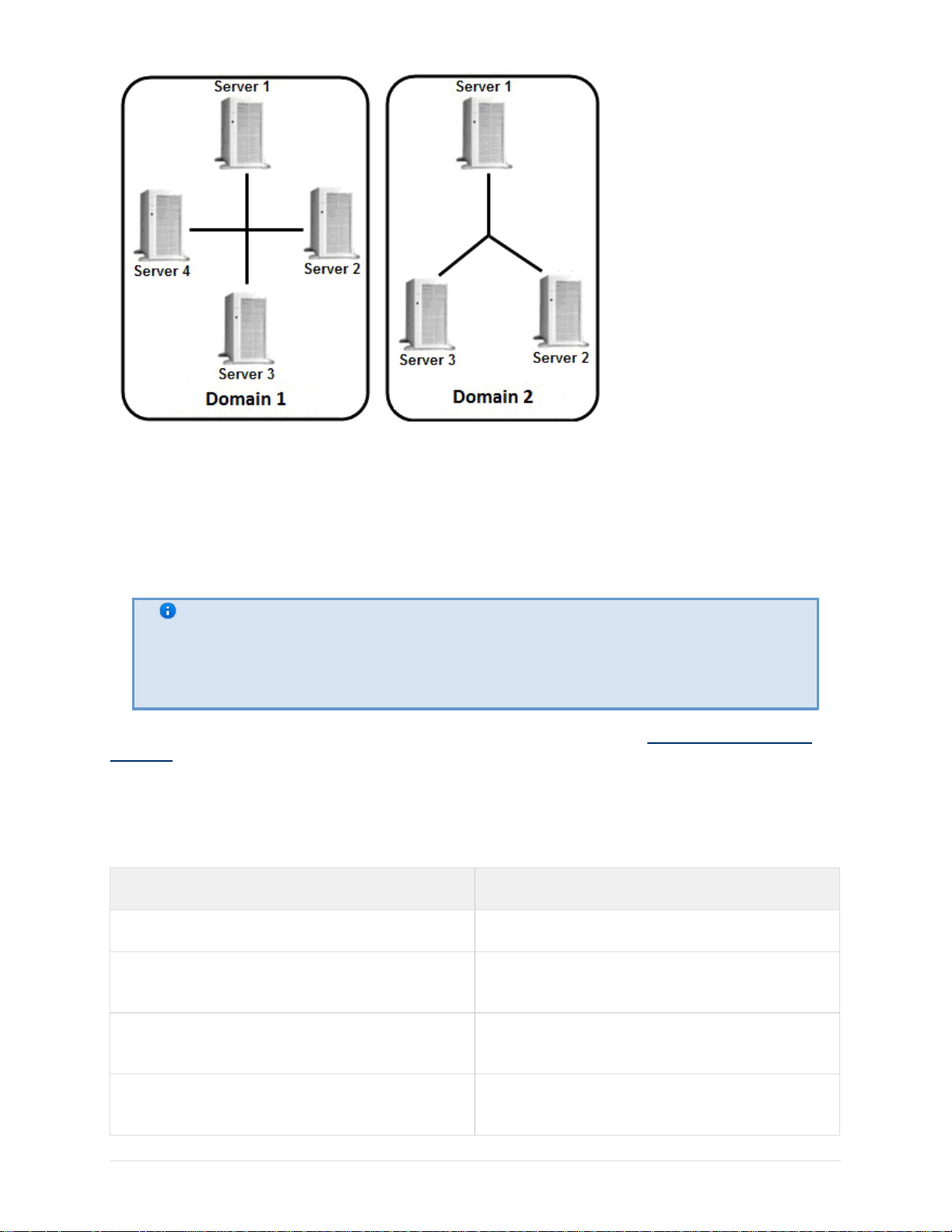
You can create a distributed system within an EyStream Domain on EyStream.
EyStream Domain – a selected grou p of computers on which the server configuration of the
EyStream software package is installed. Linking the serv ers in a group makes it possible to set up
interaction between them, thus organizing a distributed system.
Only servers which belong to the same EyStream Domain can interact.
Page 16
eLineTechnology.com
303.938.8062
A distributed security system based on the EyStream software package offers the user the
following functional capabilities:
1. Viewing and manual processing of video and audio data from several servers on one client
2. Controlling video cameras connected to various servers from one client
3. Configuring all servers of the distributed system on one client
4. Execution of automatic responses when detection tools are triggered (audio notification,
triggering of relays, SMS and e-mail notification, etc.) within the distributed system.
Note
EyStream provides the capability to build a distributed security system over a
virtual private network (VPN) by using OpenVPN software. To receive a utility for
automatic VPN configuration, contact EyStream technical support
EyStream Domain configuration is described in detail in the section titled Configuring EyStream
domains.
Specifications of the EyStream Software Package
16
Security systems based on the EyStream software package have the following primary
characteristics.
Characteristics Value
Number of servers in the distributed system Unlimited
Number of clients which support simultaneous
Unlimited
connection to the server
Number of servers which simultaneously
Unlimited
transmit video images to a client
Number of video capture channels for "live
Unlimited
video" processing on one Server
Page 17

eLineTechnology.com
303.938.8062
Number of simultaneously processed signals
coming from microphones
Unlimited
Number of audio output channels (to speakers,
headphones, etc.)
Number of PTZ devices used Unlimited
Number of video images displayed
simultaneously on a client's screen
Analog video camera support yes (through video capture cards)
IP device support
Number of archives in the system Unlimited
Video compression algorithms MJPEG, MPEG-2, MPEG-4, MxPEG, H.264,
Hardware decompression of vi deo H.264 on NVIDIA graphics cards which support
depends on the sound card used for playback
up to 25
IP cameras and IP video servers This list is
continuously expanding: support for new
hardware is added through updates to
EyStream
Motion Wavelet
CUDA
Driver Pack
Available video image resolutions resolutions supported by video cameras
Support for embedded video camera analytics yes
Support for touchscreens yes
Implementation Requirements for the EyStream
Software Package
Limitations of the EyStream Software Package
When working with EyStream, the u ser must keep in mind the limitations that the developer has
imposed on the system in order to ensure its operability.
No. Limitation
17
Page 18

eLineTechnology.com
303.938.8062
1
To work with EyStream software the
minimal requirements for OpenGL
are to be
following
fulfilled:
1.
version 1.3;
2.
Availability the ARB_vertex_program ext
ension.
Recommended requirements for OpenGL as
follows:
1.
version 2.0 and higher;
2.
Availability the ARB_vertex_program, GL
_EXT_blend_func_separate, GL_ARB_f
ramebuffer_object extensions.
Extensions availability can be checked using
the OpenGL Extension View er program (downl
oad).
This program also contains a large database of
data on OpenGL support in video cards of
various vendors.
2 To install EyStream, you must log in to
Windows as an administrator.
3 The computer name can contain only Latin
characters, Arabic numerals, and/or a minus
sign ( - ).
4 For proper installation of EyStream, there
should be no spaces at the beginning of the
name of the folder which contains the installer
5
Once EyStream has been installed, the
computer name cannot be changed
6
For all features of EyStream to work
the system must not have any
network activity. Make sure
restrictions on
that access is
properly,
open to all TCP and UDP ports
7 It is not possible to transfer a license from one
computer to another.
8
If you change any 2 of the basic hardware
components (motherboard, processor, hard
disk, video adapter, RAM, and network card)
on the computer hosting the EyStream
Server, your license will be invalid.
For example, this is the case when you chan ge
both CPU and motherboard. However,
changing a graphics card or upgrading RAM
will not affect the license.
18
Page 19

eLineTechnology.com
303.938.8062
9
Time must be synchronized among all
computers in the system (to be configured by
the user)
10
When using NOD32 Antivirus, it is strongly
recommended to either disable the Web
Access Protection service or to add the IP
addresses of IP cameras to the list of
exceptions for anti-virus scanning
11
Before installing EyStream, make sure the
video card drivers on the computer are fully up
to date
12 Users should access computers remotely by
using a NetBIOS name
13
The NetBiosName of the computer may
contain up to 15 characters.
14
When configuring the firewall, limiting the
network activity by ports is not allowed, since
EyStream uses the entire range of TCP ports
15 The Client cannot be started on a remote
desktop through the Remote Desktop
Connection utility built into Windows
16
In the current implementation , all users of the
EyStream software package should log in as
Administrators (see the sectio n titled Creatin
g and Configuring the Role and User System
Objects).
17 If a computer is linked to an Active Directory
domain, one of the following conditions must
be met to enable disk access:
1.
Access control lists must contain only local
or built-in groups and users.
2.
Create an EyStreamFileBrowser user in
the
domain and add it to the Users group.
This behavior is typical only of file systems
that have access permissions (for example,
NTFS).
Operating system requirements
EyStream software package is compatible with 32-bit and 64- bit licensed versi ons of Microsoft
Windows operating system.
Windows version Supported edition Note
19
Page 20

eLineTechnology.com
303.938.8062
Windows XP SP2
(x64)
Windows XP
Professional
OS edition, enabling to use all realized product
features
Windows XP SP3
(x86)
Windows Server 2003
R2 SP2 (x86, x64)
Windows XP Home
Edition
Restrictions, imposed by OS edition (1 physical
processor, 5 SMB connections) – see
http://www.microsoft.com
Windows XP
Professional
Windows XP Tablet PC
Edition
Windows XP Media
Center Edition
Standard Edition OS edition, enabling to use all realized product
OS edition, enabling to use all realized product
features
OS edition, enabling to use all realized product
features
OS edition, enabling to use all realized product
features
features
Enterprise Edition
OS edition, enabling to use all realized product
features
Datacenter Edition OS edition, enabling to use all realized product
features
Web Edition
(x86)
Restrictions, imposed by OS edition (2 Gb
RAM, 2 physical processors) – see
Windows Vista SP2
(x86, x64)
Windows Server 2008
SP2 (x86, x64)
http://www.microsoft.com
Home Basic
Restrictions, imposed by OS edition (1 physical
processor, 5 SMB connections) – see
http://www.microsoft.com
Home Premium Restrictions, imposed by OS edition (1 physical
processor) – see
http://www.microsoft.com
Business OS edition, enabling to use all realized product
features
Enterprise
OS edition, enabling to use all realized product
features
Ultimate OS edition, enabling to use all realized product
features
Enterprise
OS edition, enabling
to use all realized
product features.
Full Installation type
is supported.Server
Core Installation type
is not supported
20
Page 21

eLineTechnology.com
303.938.8062
Datacenter
OS edition, enabling
to use all realized
product features.
Windows Server 2008
R2 SP1
(x64)
Standard
OS edition, enabling
to use all realized
product features.
Web OS edition, enabling
to use all realized
product features.
HPC OS edition, enabling
to use all realized
product features.
Enterprise
OS edition, enabling
to use all realized
product features.
Datacenter
OS edition, enabling
to use all realized
product features.
Standard OS edition, enabling
to use all realized
product features.
Full Installation type
is supported.Server
Core Installation type
is not supported
Windows 7 SP1 (x86,
x64)
Web OS edition, enabling
to use all realized
product features.
HPC
OS edition, enabling
to use all realized
product features.
Foundation
OS edition, enabling
to use all realized
product features.
Starter
(x86)
Restrictions, posed by
OS edition (2GB of
main memory, 1
physical processor, 1
monitor) - see http://
www.microsoft.com
Home Basic
Restrictions, posed by
OS edition (1 physical
processor) - see http:
//www.microsoft.com
Stretch cards are
supported in 32-bit
version only
21
Page 22

eLineTechnology.com
303.938.8062
Home Premium
Restrictions, posed by
OS edition (1 physical
processor) - see http:
//www.microsoft.com
Professional
OS edition, enabling
to use all realized
product features.
Enterprise
OS edition, enabling
to use all realized
product features.
Ultimate OS edition, enabling
to use all realized
product features.
Requirements for Personnel Quantity and Qualifications
The following roles have been defined for operating the EyStrea m software package:
1.
Security system administrator
2.
Security system operator
In special cases, one person can perform the functions of both the administrator and the operator.
The main duties of the administrator are to:
1.
Update, configure, and monitor the operability of the security system’s hardware
2.
Install, update, configure, and monitor the operability of basic and system software
3.
Install, configure, and monitor software applications
4.
Manage user accounts (this duty can be carried out by a user entrusted with system
administrator permissions ).
The administrator must have the skills necessary for network configuration, including routing and
firewall, as well as NetBIOS, DNS, and NTP network services.
Besides, the administrator must have high qualifications and practical experience installing,
configuring, and administering the software and hardware employed in the software package.
The software package is structured so that all accessible functionali ty can be managed by one
administrator or administration responsibilities can be divided among several users.
The main duties of an operator are to:
1.
Work with the software’s GUI (graphical user interface)
2.
Optimize the performance of the personal computer to carry out tasks using the
functionality provided in the software package
3.
Create roles and users in the system (if the user has been granted the appropriate
permissions)
The system operator must have experience wi th, and be a qualified user of, PCs running Microsoft
Windows and must be able to easily perform basic operations.
22
Interface of the EyStream Software Package
The interface of the EyStream software package consists of three expanding menus:
Page 23

eLineTechnology.com
303.938.8062
1. Layouts
2.
Alarms
3.
Options
When you click a tab’s icon, the tab expands and the previously expanded tab coll apses. One of
the menus is always expanded.
Access to any given menu is configured individually for each role in the system (see the section
titled Creatin g and Configuring the Role and User System Objects).
If the appropriate settings are enabled (see the section titled Configuring auto hide for panels ),
when there is no activity in the system, the sys tem first shrinks and then hi des the panel for
switching between menus, i.e., the control panel.
Installing the EyStream Software Package 3.0
Installing equipment
Types of Devices Used
An IP device is the source of the video signal (video data) for the EyStream software.
Note
You can connect analog video cameras to EyStream via video capture cards, which
the software defines as IP devices
The following types of equipment are IP video and audio surveillance devices:
1. IP video cameras
2. Various types of IP video servers
IP video servers which use analog video cameras directly connected to them, digi tize the analog
video signal, and transmit it to users via TCP/IP. When working with analog video cameras
connected to IP video servers, users can utilize the same video image viewing and transmissi on
functions as with IP video cameras.
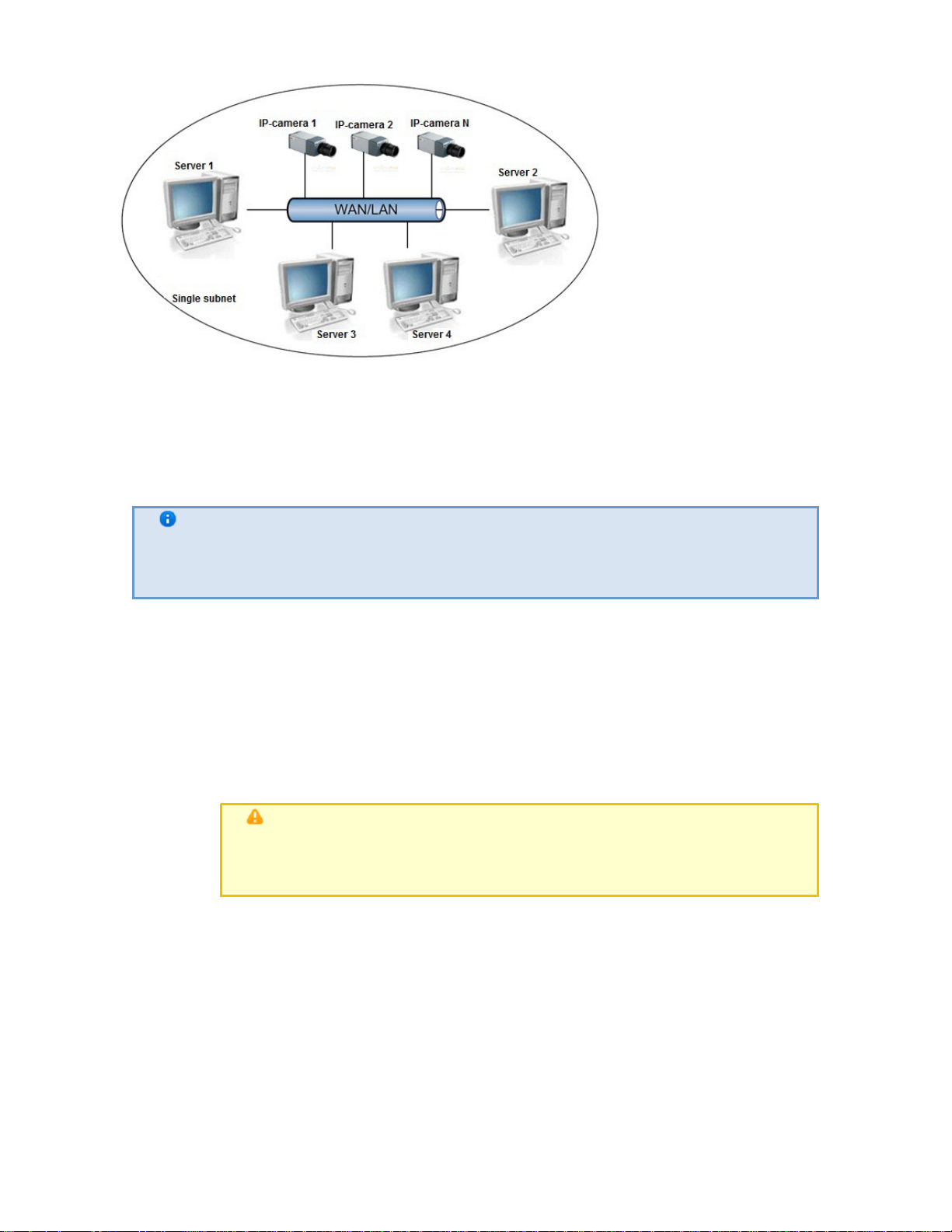
Connecting IP Devices
To work with IP devices, you need to connect the EyStream server to the local network where the
required IP devices are enabled.
23
Page 24
eLineTechnology.com
303.938.8062
Based on the video signal coming in from the IP device, an assessment is made of the guarded
location and the system responds to events registered for that location. The content and quality of
the obtained video information depends on how the IP device is installed and configured. There
are a number of rules that must be followed to obtain a high-quali ty video signal. In parti cular,
high-quality peripheral equipment (switch/router) must be used; Home/Of fice devices, which are
not intended for use in these kinds of security systems, are unacceptable.
Note
IP devices connected to such equipment will transmit a video stream with an
unacceptably long delay (from 1.5 to 3 seconds per frame)
Detailed information about creating a local network and connecting IP equipment to it is presented
in the corresponding reference documents.
Configuring IP Devices in Windows
IP devices can be configured in Windows by using the following software:
1. Software included with the IP device This software is used to accomplish the following tasks:
a. Searching for network devices connected to the local network
b. Preliminary IP address assignment (without account of routing)
Attention!
Without assigning preliminary IP addresses to the devices, it is not
possible to access their Web interface
2. Web interface of the IP device. This interface is used to accompl ish the following tasks:
a. Configuring the IP devices with consideration for routing
b. Configuring modes for the IP devices to work with video and audio signals
Configuration of IP devices in Windows is described in detail in the official reference
documentation for the respective devices.
c. Viewing video images coming in from IP devices in standard Web browser mode
24
Particulars of Configuration of Devices
Page 25
eLineTechnology.com
303.938.8062
Axis IP Devices
On page:
Stretch Cards
IP devices which partially support the ONVIF protocol
Sony IP Devices
Axis IP Devices
For Axis IP devices on which the Bonjour function is supported and enabled, changing the default
value of the Friendly name parameter is strongly discouraged. If an arbitrary Friendly name val
ue is set for an Axis IP device, a search for connected equipment in the EyStream software
package will give incorrect results for this IP device.
Note
The Friendly name parameter is configured through the Web interface of the IP
device: Setup -> System options -> Network -> Bonjour
Note
The default value of the Friendly name parameter is as follows: AXIS <model
name> - <mac address>, where <model name> is the model of the Axis IP
device and <mac address> is its MAC address (for example, AXIS 214 -
00408C7D2610
Stretch Cards
Only video cameras that support the same television standard can be simultaneously connected to
VRC6004, VRC6008,VRC6404HD, VRC6416, VRC7008L and VRC7016LX Stretch cards: they must
support either PAL or NTSC. The TV standard used in video cameras connected through a Stretch
card is set automatically during launch of the EyStream software package. Changes in the TV
standard parameter are invalid.
Note
The TV standard parameter is located in the Video stream settings group, in
the properties of the Camera object, which is a child of the Stretch card object
Attention!
For video cameras connected through Stretch cards, it is impossible to display
object tracking from embedded detection units in the viewing tile in EyStream
IP devices which partially support the ONVIF protocol
To connect IP devices which only partially support ONVIF functions to the EyStrea m software
package, you must use an ONVIF driver (1) with compatibility mode enabled.
Note
Such video cameras include Hikvision models and early versi ons of firmwa re from
Sony, Samsung, and others.
25
Page 26
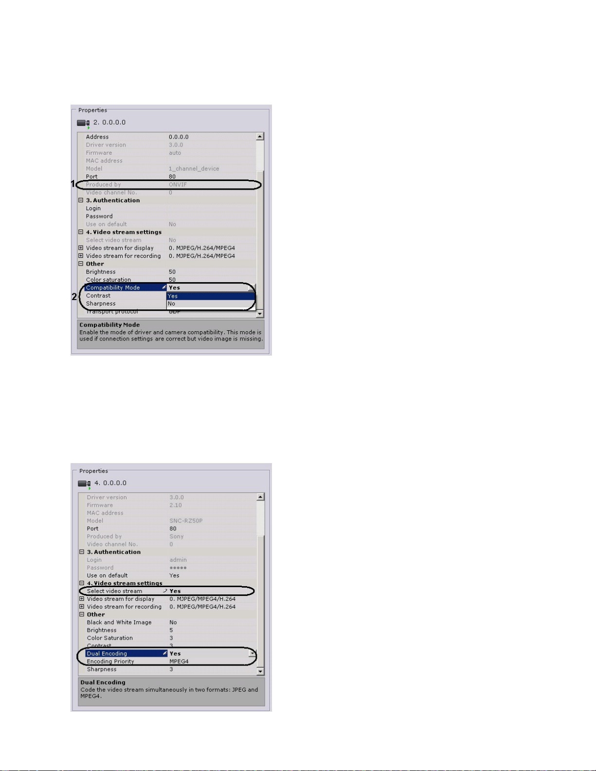
Compatibility mode makes it possible to receiv e a video image from video cameras; however,
eLineTechnology.com
303.938.8062
some capabilities of the EyStream software package will be unavailable.
Enabling compatibility mode for a video camera (2) connected using the ONVIF protocol (1) is
recommended if the connection settin gs are correct, but there i s no video image.
Sony IP Devices
Some Sony models support encoding of the video signal in two formats simultaneously. To use
this option you must perform the following steps:
1.
Select the value Yes for the Video stream selection and Dual encoding settings.
2.
From the Codec priority list, select the codec which will take priority when dual encoding.
26
Page 27

Installation the EyStream Software Package
eLineTechnology.com
303.938.8062
Types of Installation
The following two types of installations are available when installing EyStream to a personal
computer:
1.
Server and Client— This type of installation is used to accomplish the following tasks:
a.
Physical connection to a personal computer and software configuration of video and
audio capture devices (video cameras, microphones), event generation devices
(sensors, relays, etc.), and hard disks for organizing data archives
b.
Configuring the security system architecture (creating the necessary system objects
and defining the connections between them)
c.
Installing the software's user interfaces, which enable any user to connect to any
server within a single security system and to perform
administration/management/monitoring of a guarded location based on the
permissions granted by the administrator
2.
Client – This type of installation is used for installing the software's user interfaces, which
enable any user to connect to any server within a single security system and to perform
administration/management/monitoring of a guarded location based on the permissions
granted by the administrator.
The way in which the basic properties of a computer in the security system depend on the type of
EyStream installation is presented later.
Properties / type of
Client Server and Client
installation
A constant connection to
+ -
another machine is required
Devices are connected locally - +
A local user interface is
+ +
available
Installation
To install EyStream, regardless of the type of installation, you must perform the foll owing steps:
1.
Insert the EyStream installation CD into the CD-ROM drive. A dialog box will display the
disk content
27
Page 28
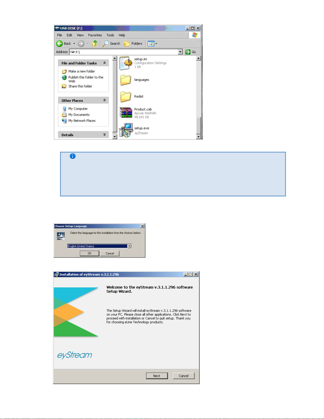
eLineTechnology.com
303.938.8062
Note
The EyStream distribution package requires installation packages for .NET
Framework 2.0 or .NET Framework 3.5 SP1. eyStream installation package will
automatically install
that software prior to installing the EyStream software
2. Run the Setup.exe file.
3. In the dialog box, choose the desired language from the list and click OK.
28
This setup wizard will now prepare for installation.
If .NET Framework 3.5 SP1 is not installed already, you will be asked to install it. To do this,
you must agree with the license agreement i n the .NET Framework 3.5 SP1 installation
Page 29
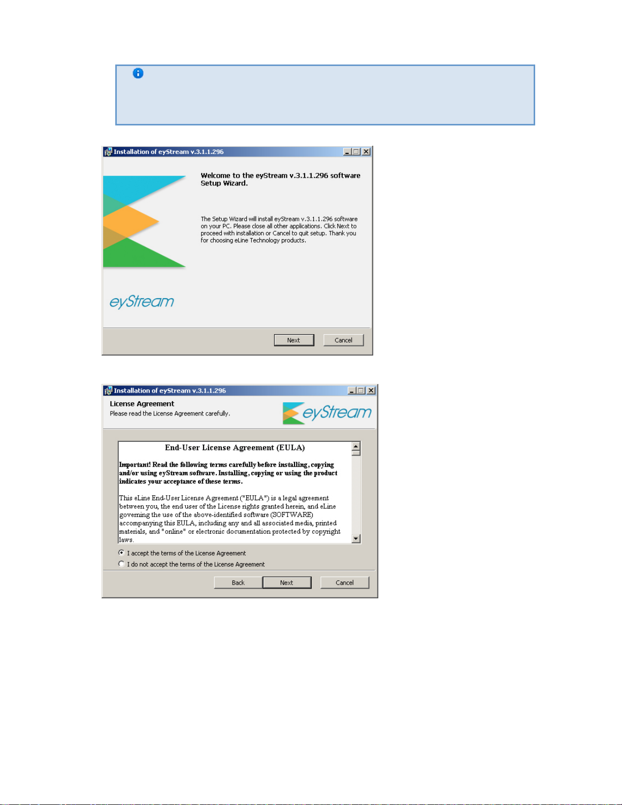
eLineTechnology.com
303.938.8062
Note
program and then follow its interactive instructions.
The .NET Framework 3.5 SP1 software is automatically bundled only with
Windows
4. Click Next on the setup wizard's welcom e screen.
5. To proceed with installation, accept the terms of the license agreement by sel ecting the
radio button next to I accept the terms of the License Agreement and click Next.
6. Select the EyStream software installation type in the dialog box by clicking the appropriate
option button and click Next.
29
Page 30
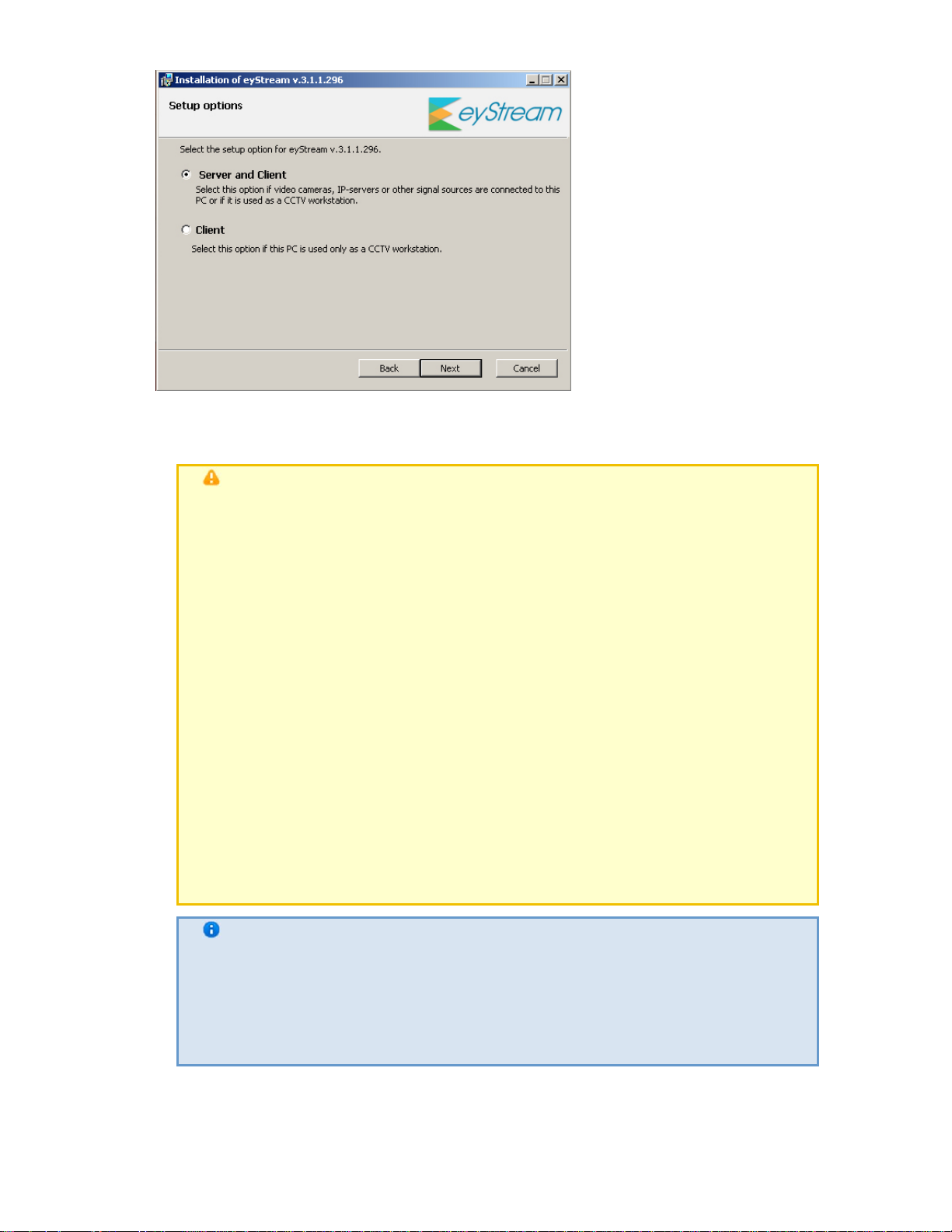
eLineTechnology.com
303.938.8062
7. Indicate the destination folders for installation of EyStream components and click Next.
Components include both EyStream and the databases used in its operation: the log
database and the object trajectory database.
Attention!
You are advised to place the log database and object trajectory database
on a disk that has sufficient space. If you will be using only a log database,
the disk capacity must be at least 5% larger than the archive size. If you
will also be using a trajectory database, the di sk must b e at least 15%
larger than the archive.
When determining the required disk size, the siz e of the trajectory
database can be calculated with the following formulas:
Size of object trajectory database = N×T×( 0,5Gb / day)– sufficient
disk size;
Size of object trajectory database = N×T×(1Gb / day)– sufficient disk
size plus reserve sp ace;
Size of object trajectory database = N×T×(5Gb / day)– sufficient disk
size plus a large reserve.
N equals the number of video cameras in the system actively recording
metadata; T equals the period of time (number of days) that metadata will
be stored. By default, T = 30 days.
Note
By default, the software will be installed to the directory C:\Program
Files\AxxonSoft\. By default, the log database and the object trajectory
database will be placed in the directory C:\Program
Files\AxxonSoft\AxxonSmart\Metadata (in the pg_tablespace and vmda_db
subdirectories,
respectively)
30
Page 31

Note
eLineTechnology.com
303.938.8062
To add quick launch shortcuts or desktop shortcuts, select the
corresponding check boxes
8. Select a user account in the file browser:
Note
The file browser helps to navigate through the Server's file system (such as
when choosing disks for log volumes). The user account for th e Windows
file browser will be created with administrator privileges.
a. Create a new account; the default name selected will be AxxonFileBrowser.
b. Use the account of the current user.
c. Create a new account; the user name and password are set independently.
31
9. Enter an EyStream Domain name to create a new group of computers based on the
computer.
If you want to add the computer to an EyStream Domain at a la ter time, select
Do not add to
Page 32

eLineTechnology.com
303.938.8062
Note
EyStream Domain. Click the Next button.
When reinstalling EyStream, you have the option of using the previous
EyStream Domain
Note
Assigning the same EyStream Domain name to several Servers does not
guarantee that those Servers will be in the same EyStream Domain. To
place
all Servers into one EyStream Domain, you must use the EyStream
interface
Domain
EyStream domains
to add each Server to the necessary EyStream Domain. EyStream
configuration is described in detail in the section titled Configuring
32
A dialog box then appears, showing the installation parameters corresponding to the
selected type of installation.
Page 33

eLineTechnology.com
303.938.8062
10.
Verify the selected installation options and click the Next button to start installation of
EyStream. The software pre-requisites are installed fi rst, including the PostgreSQL 9 .2.2
database server. If an earlier version of PostgreSQL is installed on the computer, it is
updated to version 9.2.2 in the background. A new log database is created automatically,
with the name "ngp", user name "ngp", and password "ngp".
33
Then EyStream itself is installed.
Page 34

eLineTechnology.com
303.938.8062
A message indicating the completion of EyStream installation will appear in a new dialog
box.
34
11.
Click Finish to confirm completion of the installation.
Installation of EyStream is now complete.
Repairing Installation
A repair installation is used to re-install all components of the EyStream software package. To
start a repair installation, launch the EyStream software installer from the installation CD
without removing the previous version of the program.
Note
To ensure that EyStream is re-installed correctly, all related applications should
be closed before starting the repair installation
To run a repair installation of the EyStream software, you must perform the following steps:
1. Insert the EyStream installation CD into the CD-ROM drive. A di alog box will display the
Page 35

disk contents.
eLineTechnology.com
303.938.8062
2.
Run the Setup.exe file.
3.
Click Next on the setup wizard's welcome sc reen.
4.
A dialog box will appear, allowing you to choose an operation.
5.
Select the Repair option and click Next.
35
Page 36

A dialog box will appear, showing the EyStream repair process.
eLineTechnology.com
303.938.8062
A dialog box will appear, indicating the completion of the repair proc ess. Click Finish. Repair of
EyStream is now complete.
Removal
The EyStream installation program can also remove the software. Use this option when you
need to remove all components of EyStream from your computer.
Note
All related applications should be closed before beginning removal of the
EyStream software
You can launch the EyStream removal process usi ng one of the f ollowing methods:
1. from the Start menu
2. using Add or Remove Programs in the Windows control panel
3. using the installation CD (by launching the Setup.exe file)
When you do this, the setup wizard's welcome screen appears. To remove EyStream, you must
observe the following procedure:
1. Click Next on the setup wizard's welcome screen.
36
Page 37

A dialog box will appear, allowing you to choose an operation.
eLineTechnology.com
303.938.8062
2.
Select Remove.
3.
To save your EyStream settings in a database, select the Save configuration check box.
This option may be useful when updating the product.
4.
Click Next.
A dialog box will appear showing the EyStream removal process.
37
Page 38
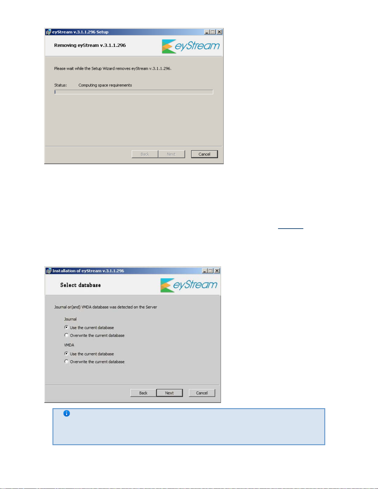
eLineTechnology.com
303.938.8062
A dialog box will appear, indicating the comple tion of the removal process. Cl ick Finish. Removal
of EyStream is now complete.
Update
If you need to install a new version of the EyStream software package but want to keep your
existing configuration and databases, complete the following steps:
1. Remove the currently installed version of EyStream (see the section titled Removal).
2. Install the new version of EyStream in the same folder where the older (removed) version
had been installed. You can place your databases in any folder you want. When i nstalling
the new version, select the Use the current database radio button (for the log and object
trajectory databases) in the Select database window.
38
Note
If you do not need to retain existing databases, select the Overwrite the
current database radio button
Licensing of the software product
Page 39

EyStream license types
eLineTechnology.com
303.938.8062
Upon installation, the software will be launched in demo mode. The system will operate in demo
mode from 8:00 AM to 6:00 PM. The software has no other limitations, functional or otherwise,
when running in demo mode.
The EyStream software package must be activated in order to utilize the full functionality of the
security system. You can activate the software by distributing an activation key on the system.
Data on all the types of EyStream licenses is presented below.
Type of
license
Demo mode
from 8 AM to
6 PM
EyStream
Free Version
EyStream Unlimited Unlimited Unlimited
Number of
servers in
the system
Unlimited Unlimited
1 (fixed) 16 (fixed) 1 terabyte None Free
Number of
video
channels
per server
Archive
volume
Unlimited
(limited only
by available
disk space)
(limited only
by available
disk space)
Forensic
Search
enabled
Yes Free
Yes (as
needed)
Cost
Please
contact eLine
to inquire
about
price
the
EyStream Free Version can be upgraded to EyStream. Upgrades must be purch ased. Upon
upgrade, you can use unlimited storage. Also, if you upgrade, you can purchase additional
licenses for Forensic Search in archive and for servers and/or video cameras.
In the case of an EyStream license, an upgrade can be obtained for increasing the nu mber of
servers and video cameras in the system or adding the Forensic Search capability.
Note
When you upgrade your license, you cannot reduce the number of video channels
Information about the type of license you are using is displayed i n the serv er properties in the Pro
duct Type field: EyStream Free Version or EyStream.
Linking the license file to computer hardware
The license file contains data on basic hardware configuration (motherboard, processor, hard disk,
video adapter, RAM, and network card) of all Servers. If you change any 2 of the basic hardware
components, your license will be invalid. For example, this is the case when you change both CPU
and motherboard. However, changing a graphics card or upgrading RAM will not affect the
license.
Note
If you install virtualization products such as VirtualBox, VmWare etc. , this may
affect the license. Should you encounter this problem, you are advised to
uninstall all virtualization products or apply for a new license file
39
Page 40

This is why when working with EyStream you should bear in mind the following:
eLineTechnology.com
303.938.8062
1. The activation request should be sent from the computer that will host the EyStream
Server.
2. You can upgrade your license only if you retain the initial basic hardware configuration of all
the Servers.
3. It is not possible to transfer a license from one computer to another.
Product Activation Utility
License activation for the EyStream software package is carried out throu gh the product activation
utility.
You can launch the product activation utility from the Windows Start menu: Start -> All
Programs -> EyStream -> Utilities -> Program Activation.
Note
The product activation utility program file LicenseTool.exe is located in the folder
<Directory where EyStream is installed>\EyStream\bin\
Then you must select the name of one of the EyStream Domain servers to which the license f ile
will be applied (the file is applied to all EyStream Domain servers launched at the moment of
activation)
continue the
and connect to the system, under an administrator's user name and password, to
activation process.
40
When the utility has loaded, its main will be displayed.
Page 41

eLineTechnology.com
303.938.8062
License Activation
To activate EyStream, please refer to the document titled Activation Guide,
step-by-step instructions on activating, updating and upgrading EyStream .
It is also recommended that you use the prompts displayed in the product activation utility's
dialog boxes .
which presents
Launching and Closing the EyStream Software
Package
Startup
Starting a Server
The EyStream Server i s started automatically when the operating system starts.
If a Server’s operation was stopped, you must complete one of the following actions to restart the
Server:
1.
Restart the system
41
Page 42

2. Select Start -> All Programs -> EyStream -> Start Server
eLineTechnology.com
303.938.8062
3. Start NGP Host Service
Starting an EyStream Client
The EyStream client can be started manually using the Start menu, which is intended for
launching user programs in Windows. To start working with the software, perform the following
steps:
1. Select Start -> All Programs -> EyStream -> EyStream
Note
The EyStream software package program file AxxonNext.exe is located in
the folder <EyStream installation folder>\AxxonSmart\bin\
The EyStream client will then launch and an authorization window will appear
2. Enter the user name and password and click Connect.
Note
If the software is accessed by a remote user, the NetBIOS name or IP address of
the computer with which the connection is established should be indicated in the
Computer field
Note
The first login to the system is done with the user root, which has admini strator
permissions . Enter root in the User Name and Password fields. The
administrator then needs to configure the system for multi-user acces s described
in detail in the section titled Creating and Configuring the Role and User System
Objects)
If authorization is successful, a video surveillan ce monitor will be displayed on the screen.
42
Page 43

eLineTechnology.com
303.938.8062
Note
If EyStream is launched in demo mode, then after you enter the authorization
parameters, a message to this effect will appear (see the section Demo mod e
notification)
If the Server to which EyStream is connecting does not belong to any EyStream Domain , after the
Connect button in the authorization window is clicked, a message is displayed.
To connect to the Server, you must either create a new EyStream Domain based on the server or
add the Server to an existing EyStream Domain.
If you choose the first option, click OK in the message and follow the instructions given in the
section Creating a new domain. For the second option, click the button and follow the
instructions given in the section Adding a Server to an existing EyStream Domain.
43
Demo mode notification
If activation has not been completed, EyStream Free Versions in demo mode.
The system will operate in demo mode from 8:00 AM to 6:00 PM . The so ftw are ha s no oth er
limitations, functional or otherwise, when running in demo mode.
The different types of demo modes are presented in Table.
Type of demo mode Conditions EyStream operation
Active EyStream can be started
between the hours of 8:00 AM
and 6:00 PM
EyStream works without
limitation
Page 44

eLineTechnology.com
303.938.8062
Inactive
EyStream started outside
hours of 8:00 AM and
6:00
the
EyStream does not work
PM
If a Client is connected to an EyStream Domain in which there is at least one Server running in
demo
mode, an appropriate message is displayed, along with a list of Servers in the EyStream
Domain and
their types of licenses.
Note
The notification is displayed after successful authorization
If an EyStream Domain includes at least one Server running in active demo mode, you will be
given
the option to continue working (2) or start the activation utility (1).
If all Servers in the EyStream Domain are running in inactive or expired demo mode, you will be
given the option to launch the activation utility or close the Client.
44
Page 45

Shutdown
eLineTechnology.com
303.938.8062
Shutting down an EyStream Client
Before closing EyStream, you need to exit the user interfaces. To do this, perfor m one of the
following:
1. Click the button located in the top-right corner of the EyStream dialog box.
Note
If the client is opened in full-screen mode (enabled by default), the [X] is
not displayed. In this case you can exit the user interfaces using actions
2. In the Settings tab, click the button.
3. Select Exit in the context menu of the EyStrea m icon , which is l ocated on the
Windows toolbar when the program window is minimized.
When you perform one of these actions, the authorization window will appear. To close
EyStream (completely exit the client), click the Close button.
and 3
2
45
Shutting down a Server
To shut down an EyStream Server, complete one of the following actions:
1. Select Start -> All Programs -> EyStream ->
2. Stop the NGP Host Service.
Shut down Server
Switching Users Quickly
You can switch EyStream users quickly without fully exiting the client. To
do this, follow the steps below:
Page 46

1.
eLineTechnology.com
303.938.8062
Exit the EyStream user interface (see the section Shutdown).
2.
When the authorization window appears, ent er the user name under which you need to l og
in and the corresponding password and click Connect.
Switching users is now complete.
Connecting to Another Server Quickly
You can connect to another server without fully exiting the client.
To do this, follow the steps below:
1.
Exit the EyStream user interface (see the section Shutdown).
2.
When the authorization wi ndow appears, selec t the server to which you need to connect the
client from the Computer list.
3.
Enter the user name under which you need to log in and the corresponding password and
click Connect.
Connection to another server is now complete.
Configuration of the EyStream Software
Package
General Information on Configuring System Objects
Procedure for Configuring System Objects
System objects form the basis for configuring the EyStream software package; you can set them up
in the Devices section of the Settings tab.
46
Page 47

eLineTechnology.com
303.938.8062
Functions such as identifying devices physically connected to a Server and managing those
devices, creating users with varying permissions , and creating rules and automatic responses
make up just a portion of what the the user can do by creating and configuring system objects.
The procedure for working with system objects varies slightly depen ding on their typ e, but
generally you should adhere to the following sequence of actions:
1. Create an object.
2. Configure its parameters.
3. Save changes.
4. Edit the values of parameters.
5. Save changes.
6. Delete the object.
Some system object parameters have a set range of values, in which case you must select the
appropriate value from a list. Other parameters serve to display information, while yet others
must be set manually according to the recommendations in the parameter's descrip tion.
Note
As a rule, the parameter description is displayed in a special area u nder the
object properties table when the parameter is selected
47
Page 48

eLineTechnology.com
303.938.8062
As evident from the sequence listed above, ma ke sure to save any changes made during
configuration by clicking the Apply button. After you click the button, a progress bar will indicate
that the settings are being applied. You can resume working with the system after the process
completes.
Before you clic k the Apply button, the ch anges may be cleared using the Cancel button.
Otherwise the changes will be applied without having to restart the software.
List of Servers for an EyStream Domain
All servers under the same EyStream Domai n as the server you connected to are di splayed in the
list
of devices.
You can configure all EyStream Domain servers from any Client workstation, provided that you
have
the appropriate permissions (see the section Creating and Configuring the R ole and User
System Objects).
Searching for Unallocated Servers and Hardware
48
Unallocated Servers (that is, servers that do not belong to any EyStream Domain) and IP devices
shown in the system after you perform a device search. To start a search, click the
are
button.
Page 49

Note
eLineTechnology.com
303.938.8062
Since multicast packets are used for device search, the search results may not
contain the Servers and devices from other subnets
Unallocated servers found are displayed in the Unallocated Servers list. Please refer to the s ection
Adding a Server to an exi sting EyStre am
Domain
Found devices are sorted by group (based on status) in the Unallocated Equipment list.
to find out how to add them to an EyStream
Domain.
49
Page 50

Note
eLineTechnology.com
303.938.8062
To view more detailed information about a device (manufacturer, model,
firmware, etc.), select its corresponding line in the list
Icons for groups and video cameras will be in different colors dependi ng on the status of the
detected devices.
Color of video camera icon Description
Black
The device's manufacturer, model, and
firmware have been definitely determined; it
can be added to the list of devices on the
server as is.
Yellow
When adding the device to the list of devices
on the Server, check the manufacturer, model,
and firmware version used.
Red
The device's manufacturer, model, and
firmware have not been determined. Video
cameras must be manually added to the
Server's equipment list (wi th the help of the
tool ).
The desired unallocated equipment marked with and must be linked to the Server, after
which it will be displayed in the list of devices on the Server and will be accessi ble for further
configuration. Devices marked with can be linked to a Server with the tool by selecting
the server in the object tree.
50
Attention!
Compatibility of devices marked with in EyStream is not guaranteed
If you remove a server from an EyStream Domain, the server automatically joins the
Unallocated Servers list, if the current Client was connected to another serv er. If the current
Client was
connected to the removed Server, the user interfaces will close.
When a device is deleted from the list of devices on a server, i t is automatically placed in the
Unallocated Equipment list.
Page 51

Devices are listed under Unallocated Equipment without verification of their presence on the
eLineTechnology.com
303.938.8062
network. To refresh these lists, you must launch a device search (by usin g the button).
Creating Device Objects Manually
You can create objects in EyStream either by using the tools located above
the object tree or by using the link, depending on the object type. You can then
configure the objects and save changes.
Note
If the settings of a newly created object are not saved, the , icon will appear
on the tab, literally indicating that the changes to the tab have not been saved.
Then, when you are exiting the program, a message will appear, asking whether
you want to exit without saving changes
Object search
EyStream allows you to search for objects in the objects tree using only part of thei r name. An
object search can be performed on all tabs under Devices.
To search for objects, complete the following steps:
1. Select the tab containing the object tree that you need to search
51
2. Enter the full or partial name of the object in the Search… box.
Note
Search is not case-sensitive
Note
A search can also be run based on object ID
The search starts automatically once you enter something in the box. When the search is
complete, you will see the number of objects found in the tree, along with the currently displayed
search results highlighted in beige.
Page 52

eLineTechnology.com
303.938.8062
The parts of names corresponding to the characters you entered will be highli ghted in yellow on
the found objects.
Note
If a found object is located in a collapsed branch of objects, the bran ch will be
highlighted in yellow
To move between search results, use the buttons.
The search results rotate in a loop; moving from the last object takes you back to the first object.
Note
If you move to an object located in a collapsed branch, the branch will
automatically expand
Configuring EyStream domains
A distributed system based on the EyStream softwar e package is created within an EyStream
Domain, i.e., a selected group of EyStream Servers.
When configuring EyStream Domains, the following operations are used in the necessary
combinations:
1. Creating a new domain
2. Adding a Server to an existing EyStream Domain
3. Excluding a Server from the current EyStream Domain
To configure EyStream Domains, you must have the appropriate permissions (see the section
Creatin
g and Configuring the Role and User System Objects).
This section gives step-by-step instructions for each operation used in configuring EyStream
Domains,
and then describes typical instances of their use.
EyStream Domain operations
Creating a new domain
A new EyStream Domain can be created in one of two ways:
1. During installation of the EyStream software package with the Server and Cli ent
configuration type (see step 8 of the instructions in the section Installation)
2. When attempting to connect to a Server which does not belong to a domain
In the second case a message will appear, in which you should click OK (see also the section Start
up).
52
Page 53
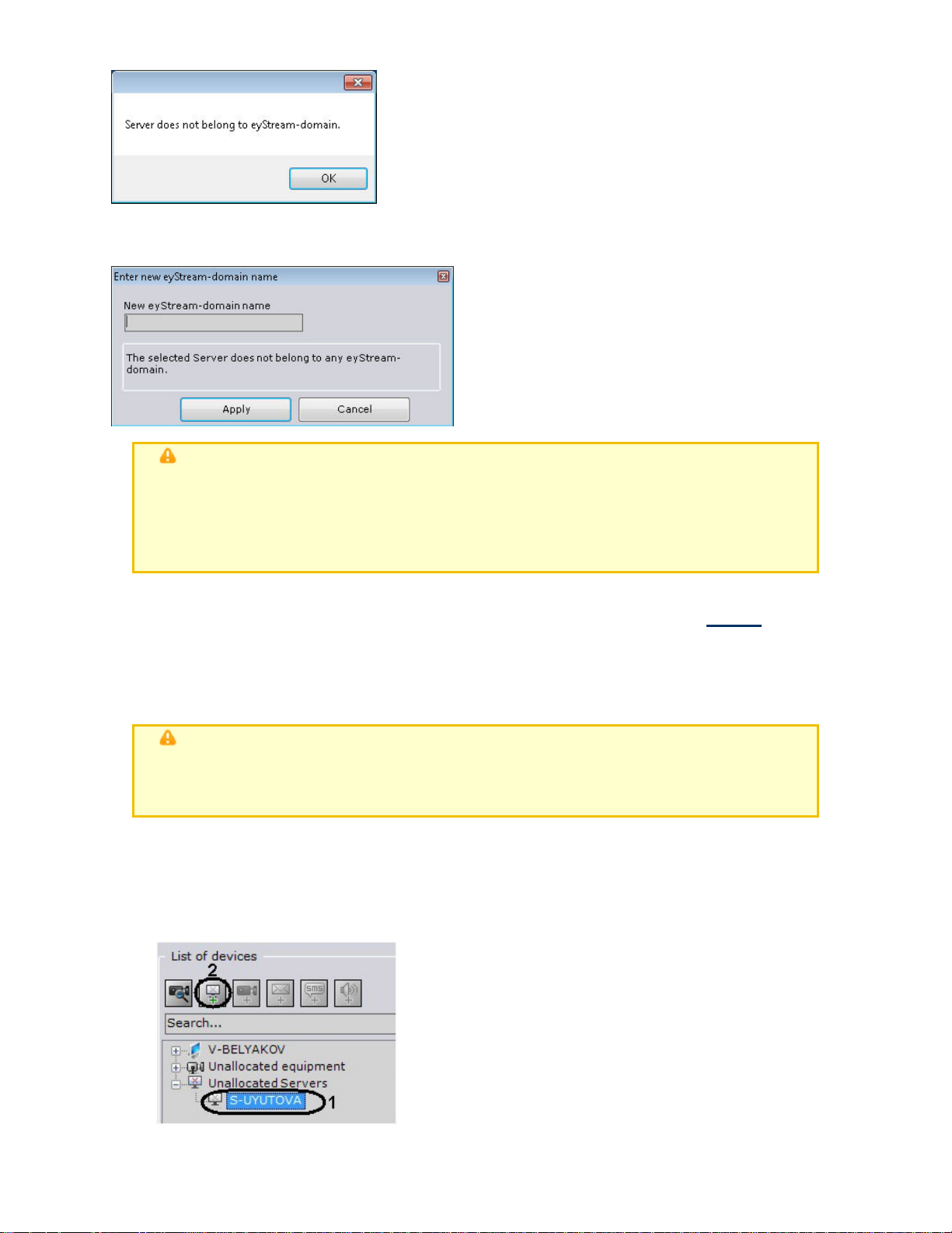
eLineTechnology.com
303.938.8062
The Name new EyStream Domain window will appear. In the New EyStream Domain name
field,
enter the EyStream Domain name to create a new group of computers based on the Server
and click
Apply.
Attention!
It is not possible to use the above steps to add a Server to an existing EyStream
Domain. Assigning the same EyStream Domain name to several Servers does not
guarantee that those Servers will be in the same EyStream Domain. Different
EyStream
This will create a new EyStream Domain based on the Server. The EyStream software package
will then be launched with the entered authorization parameters (see the section Startup).
Domains can have identical names
Adding a Server to an existing EyStream Domain
A Server can be added to an existing EyStream Domain from an y Server within that EyStream
Domain.
Attention!
Only unallocated Servers, i.e., Servers which do not already belong to any EyStream
Domain, can be added
There are two ways to add a Server to an EyStream Domain, depending on whether or not
it is
present in the search results (in the Unallocated Servers group).
If a Server is present in the search resu lts, you c an use the following procedu re to add it to an
EyStream Domain:
1. Select the Server in the Unallocated Servers group (1).
53
Page 54

eLineTechnology.com
303.938.8062
2.
Click or select Add to EyStream Domain from the context menu after right-
clicking on
The Server will then be added to the EyStream Domain from the Unallocated Servers group.
Since the search for unallocated Servers is conducted using broadcast packets, the results may
not include Servers located in a different su bnetwork (for example, beyond a router which
blocks
broadcast packets).
In this case the option of manually adding a Server to an EyStream Domain can be useful; this
option
can be used with all unallocated Servers, including those present in the Unallocated
Servers group.
A Server can be manually added to an EyStream Domain as follows:
1.
Select the option Add Server to EyStream Domain in the context menu of the
Unallocated
the group).
the Server (2).
Servers group (the menu can be brought up by ri ght-clicking th e name of
2.
When you do this, the Enter Server name window appears.
3.
In the Server Name field, enter the NetBIOS name of the Server to be added to the
EyStream
4.
Click Apply.
Domain.
The Server will then be manually added to the EyStream Domain.
After a Server is added to an EyStream Domain using any of the methods described, it will
appear in
the object tree.
54
Note
Page 55

eLineTechnology.com
303.938.8062
If a Server is not currently accessible when it is added to an EyStream
Domain, it will be displayed in the object tree with the icon
The Server will be added to the EyStream Domain as soon as the Serv er becomes ac cessible. To
cancel the addition of a Server to the EyStream Domain, you must select Undo adding Server
to
EyStream Domain from the context menu (by right-clicking on the Server name).
Removing a Server from an EyStream Domain
Any Server on an EyStream Domain can be used to remove a Server from an EyStream
Domain.
steps:
To remove a Server from an EyStream Domain, you must perform the following
1. Select the option Remove from EyStream Domain in the context menu of the Server
(the menu can be brought up by right-clicking the name of the Server).
2. In the window which appears, confirm that you want to remove the Server from the
EyStream
Domain by clicking the Yes button.
55
Page 56

eLineTechnology.com
303.938.8062
The Server will then be removed from th e EyStream Domain. If the cu rrent Client was connected
to
the excluded Server, the user interfaces will be un loaded and the user will be prompted to
repeat
the authorization procedure for EyStream (see the section Startup).
Cases of EyStream Domain configuration
All possible cases of EyStream Domain configuration are, to some degree, a combination of two
typical cases.
In the first typical case, the Servers for the future EyStream Domain are selected before EyStream
installation. This case involves the following steps:
1. Selecting a Server on the basis of which the new EyStream Domain will be created.
Installing
indicating the name of the new EyStream Domain (see also step 8 of the instru ctions in the
section Installation).
the EyStream software package with the Server and Client configuration type,
Note
Any Server in the future EyStream Domain can be selected as the primary
Server
56
2. Installing the EyStream software package with the Server and Client configuration type on
the other servers of the future EyStream Domain, without adding them to the EyStream
Domain
(see also step 8 of the instructions in the section Installation).
Page 57
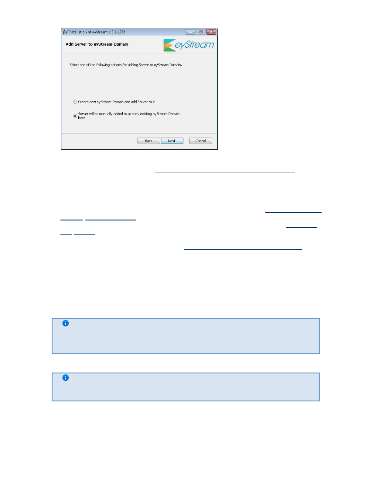
eLineTechnology.com
303.938.8062
3. Connecting to the primary server.
4. Adding the remaining Servers to the EyStream Domain from the primary Server accordin g
to
the instructions in the section Adding a Server to an existing EyStream Domain .
In the second typical case it is necessary to add servers which are part of another EyStream
Domain
to a new EyStream Domain. This case involves the following steps:
1. Excluding all the Servers which are to be added to the new EyStream Do main from thei r
current
EyStream Domains, according to the instructions in the section Removing a Server
from an EyStream Domain.
2. Naming the new EyStream Domain according to the instructions in the section Creating a
new domain, when attempting to connect to one of the Servers exclud ed in step 1.
3. Adding the remaining Servers to the EyStream Domain from the primary Server
according to the instructions in the section Adding a Server to an existing EyStream
Domain.
Preliminary Configuration of Devices
When you launch the EyStream software package for the fir st time, you can perform the
following preparatory operations:
1. Selecting IP devices to register as objects.
2. Configuring a default archive for selected IP devices.
Note
A default archive is one in which records are made when an operator initiates an
alarm
To do this, click Yes in the IP device configuration application dialog box (1).
Note
To skip the preparatory stage when launching EyStream, click N o (2)
57
Page 58

eLineTechnology.com
303.938.8062
When you do this, the IP device configuration application will launch.
When you launch this application, the program will au tomatically search for connected IP devices.
Devices which are found are displayed in the Select devices for activation list.
Note
IP devices whose vendor, model and/or firmware version has not been
determined are displayed in the Advanced configuration requi red
58
In the Select devices for activation list, select the check boxes for those devices which need
to be registered as EyStream objects and then click Apply.
If you need to search for IP devices again, click Search.
After closing the IP device configuration application (by clicking Apply or Cancel), the user will be
prompted to configure the default archive for the video c ameras (IP devices) selected in the fi rst
step.
Page 59

eLineTechnology.com
303.938.8062
To skip configuration of the default archive for the selected video cameras and start the EyStream
software package, click the Cancel button.
To configure the archive, you must perform the following steps:
1. Select the Use for archive check boxes for the disks which are to be u sed to store the
default archive (1).
Note
The following information is provided for each disk: total volume, total
occupied space, and total free space (2)
2. If you need to use an archive volume already located on the disk, select the Use current
volume check box (3).
Note
The size of the existing volume is indicated in the Use current volume fiel
d
3. Specify the archive size (minimum of 1 GB) for each selected disk ( 3). You can specify the
archive size by using one of the following four methods:
a. Move the slider to the position corresponding to the volu me of disk space allotted for
the archive.
59
b. Manually enter the archive size as a percentag e of total disk space (i n the % of the
disk field).
c. Manually enter the archive size as a percentage of free disk space (in the % of free
space field).
d. Manually enter the archive size in gigabytes (in the Archive size, GB field).
Page 60

eLineTechnology.com
303.938.8062
4. Click Apply (4).
Note
The archive size assignment field and slider are dynamically link ed; the
values in the fields change as the slider moves, and vice versa
Note
The diagram over the slider serves as a graphic representation of the disk
space used: gray represents used space, and orange represents the space
allotted for the archive being created
Note
To allot an entire volume for an archive, you must first manually delete the
file system on the disk. To do this, follow the steps below:
a. Launch the Windows Disk Management (5).
b. Delete the required volume.
c. Create a new volume in the resulting unformatted area.
d. Assign a letter to the volume, but do not format it.
Note that you cannot delete a partition on a removable disk in Disk
Manager.
Attention!
The system disk cannot be completely allocated for an archive
Note
If an archive is configured to a disk containing an old volume that is unused, a
dialog box warns you that the partition containing the archive volume will be
formatted
60
Read through the list of partitions that will be formatted. If the list is correct, select I have read
Page 61

the warning and realize the risk of losing important data, then cli ck Format. Otherwise,
eLineTechnology.com
303.938.8062
click Cancel to return to preliminary archive settings.
Configuration of the default archive is complete.
Configuring System Objects for Devices
The Server Object
The General Settings group displays information about the software package (license, driver
version, etc.) which cannot be edited.
The web server in the EyStream software package can be configured in the Web Server group of
settings (see the section Configuring the web server).
The Video Camera Object
Creation and configuration of the Video camera object is done in the Hardware tab. The object
tree of a video camera is generated automatically according to its functions which are integrated
into the EyStream software package (the presen ce of alarm inputs, relay outputs, PTZ unit,
The objects for the video cameras found on the network are first shown in the Unallocated
Equipment list. After these objects have been moved to the list of server equ ipment, their
configurations will be accessible for editing.
In the Object Features group you can see the following video camera features:
1.
MAC address
2.
IP address (determined automatically, can be changed if necessary)
3.
Manufacturer, model, firmware
4.
Driver information
5.
Port used to transmit data between the video camera and the EyStream software package
(this value is set to 80 by default but can be changed if necessary)
etc.).
61
To configure the Video camera object, perform the following:
1.
Highlight the object in the list of devi ces on the Server ( 1).
Page 62

The configuration field for the selected object will be displayed in the area on the right (2).
eLineTechnology.com
303.938.8062
2. Select Yes from the list in the Enable fi eld to enable the video camera.
3. Assign the video camera a name which will be displayed in the objects tree and in the
viewing tile, in the Name field.
The ID of a video camera object is set automatically during creation. However, it can be
edited in the corresponding field. Th e ID is also the serial nu mber of the video camera: in
theMonitor interface window and in the equipment tree of the server, the video cameras
are placed in ascending order by ID.
4. Enter the number of the network port through which data exchange between the video
camera and the software will take place, if needed. The default value i s 80.
Note
At first the port number is set through the camera's Web interface
62
Page 63

eLineTechnology.com
303.938.8062
5. If the user name and/or password for connecting to the video camera are different from the
factory settings, select No in the Use by default field within the Authentication paramete
r group and defi ne the con nectio n paramete rs.
Note
The user name and password can be changed in the video camera's web
interface
When this method of authentication is selected, the software package will connect to the
video camera with the indicated user name and password.
6. If a video camera supports multistreaming, you can configure two video streams separately:
high quality and low quality. To do so, in the Video stream selectionlist, select Yes. If
this function is not supported by the video ca mera, the val ue of this parameter wi ll not be
active.
63
Important
The high-quality video stream is used to write video to the video archive.
Either video stream can be selected for display in a viewing tile (see Selecti
ng video strea m qu ali ty in a viewi ng til e).
If a video camera does not support multistreaming, the parameters of the video strea ms are
identical. In this case only the parameters of the low- quality video stream are editabl e (the
parameters of the high-quality video stream are adjusted automatically).
Page 64

eLineTechnology.com
303.938.8062
Note
In most cases, the following parameters are set for video streams: bit rate,
compression rate, frame rate, and resolution. Detailed information on
configurable parameters can be found in the official reference
documentation for the video camera
Note
When some video stream parameters are changed, the video camera may
automatically restart, in which case it will become unavailable for some
time (depending on the video camera)
7. To configure a fisheye camera, go to the Panoramic view settings group for the camera
(see Configuring fisheye cameras).
8. Configure additional video camera parameters (such as contrast, brightness, and col or
saturation) in the Other group, based on their description in the EyStream interface or in
more detail in the official reference documentation for the video camera.
64
9. Click Apply in the bottom-ri ght cor ner of the pr ogram window to apply the new setti ngs.
Page 65
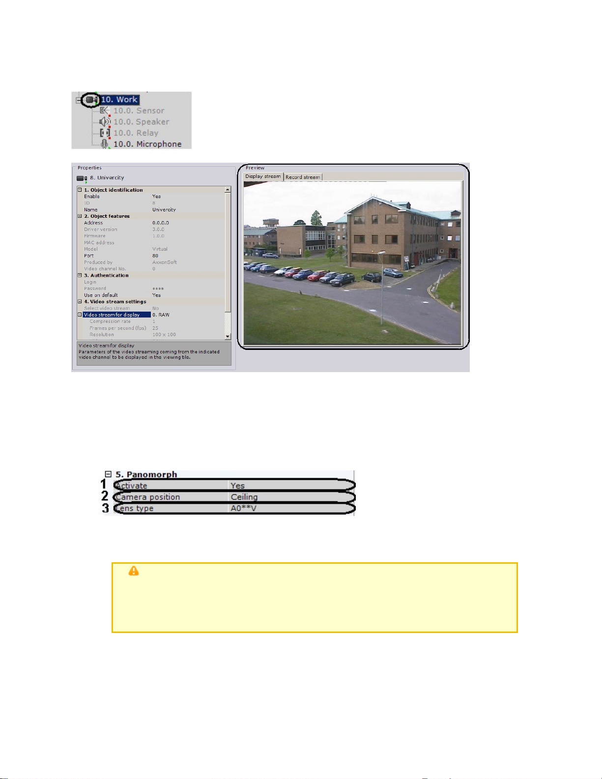
After saving the settings, the video camera will be activated and shifted to the work mode that
eLineTechnology.com
303.938.8062
corresponds to the set parameters. The Video camera icon indicator will turn green and the
image from the camera will be displayed in the preview window.
Configuring fisheye cameras
If you are using a fisheye camera or video camera wi th a panomorph lens, configure the following
settings of the Video camera object, in the Panoramic view settings group:
1. To activate panoramic view, in the Activate list (1) , select Yes.
2. In the Video camera position list (2), select the mount of the video camera.
3. If it is a fisheye camera, select the Standard fisheye lens lens type (3). If it is a video
camera with a panomorph lens, select type A0**V(3).
Important!
Some system features and functions depend on the chosen position of the
video camera: digital zoom, display of video in the surveillance sector on
the map, and immersive mode
4. Click the Apply button.
Configuration of the fisheye camera is complete.
Configuring virtual video cameras
The EyStream s oftware package enables you to work with virtual video cameras.
This requires running EyStream in test mode and consists of imitating a stream of video data by
65
Page 66

playing an available vide o clip (recording). You can play video recordings using video compression
eLineTechnology.com
303.938.8062
algorithms supported by EyStream (MJPEG, MPEG-2, MPEG-4, MxPEG, H.264, and Motion
Wavelet).
To create and configure a virtual video camera, complete the following steps:
1.
Add a Video camera object.
2.
Select AxxonSoft from the Produced by list and click Apply.
3.
In the Folder field, specify the storage location of the video clip that will be u sed to imitate
a video signal.
66
4.
Click the Apply button.
The video file in the selected folder will then be played back in a repeating cycle. If the folder
contains several files, they will all be played in a random order.
Configuring video camera groups
You can manually group video cameras to enable quicker selection of a specific video camera for
display.
Video camera groups are configured through the interface using the Devices tab (under Settings
). To configure device groups, you must have the appropriate permissions to configure devices.
Page 67

Procedure for configuring video camera groups
eLineTechnology.com
303.938.8062
To configure video camera groups, complete the following steps:
1.
Create Group objects.
2.
Add video cameras created in the system to Group objects.
3.
Create a system of groups and subgroups.
Creating a Group object
To create a Group object, complete the following steps:
1.
Go to the Groups tab.
67
Page 68
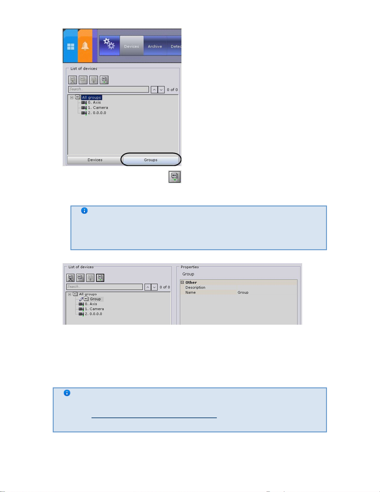
eLineTechnology.com
303.938.8062
2. To create a Group object, click the button or select Add group in the context menu
of the All groups object.
Note
The All groups object, which includes all video cameras created in the
system, is accessible by default. It is impossible to delete this object. It is
also impossible to delete video cameras from this group
3. Specify the group name in the Name field.
4. Enter a description of the group in the appropriate field.
5. Click the Apply button.
The Group object has now been created.
68
Adding video cameras created in the system to Group objects
To add video cameras to groups, complete the following steps:
Note
Video cameras are added to groups via management operations (see the section
titled Managing Group and Video camera objects). The standard method for
adding video cameras to groups is presented below
1. In the All groups group, select a video camera to add to the selected group.
Page 69

eLineTechnology.com
303.938.8062
2. Click the button or select Copy from the context menu of the selected video camera.
3. Select the Group object to which you need to add the video camera.
4. Click the button or select Paste from the context menu of the selected group.
5. Fill the groups with the necessary video cameras (see steps 1-4).
Note
6. Click the Apply button.
Adding video cameras to groups is now complete.
Creating a system of groups and subgroups
Groups can be included within other groups, forming a system of groups and subgroups.
One video camera can be assigned to multiple groups
69
A system of groups and subgroups can be created via group management operations and video
camera management operations (see the section ti tled Managing Group and Video camera objects
).
Group objects can be moved or copied into other Group objects or into the All groups object.
However, you cannot insert Group objects into their own subgroups.
Page 70

Note
eLineTechnology.com
303.938.8062
For example, in the scenario displayed below you cannot add the Group 4 object
If you nonetheless attempt to add a Group object into its own subgroup, you will receive an error
message.
into the Group 1 or Group 2 objects
Managing Group and Video camera objects
The main operations used to manage groups and video cameras are presented in table.
Action Execution
Cut/Paste
Using the context menu:
Note
You can cut a Video camera
object only from a Group obj
ect. You cannot cut a Video
camera object from the All
groups object. It is also
impossible to cut the All
groups object
1. Bring up the context menu by right-clicking
the Video camera/Group object.
2. Select Cut.
3. Bring up the context menu by right-clicking
the Group object (or the All groups object
if you want to move one of the groups) to
which you want to move the Video
camera/Group object.
4. Select Paste.
70
Page 71

eLineTechnology.com
303.938.8062
Using your mouse:
1.
Left-click and hold the Video
camera/Group object.
2.
Drag the object to the Group object (or to
the All groups object if you are dragging a
Group object)).
3.
Release the left mouse button.
Using the toolbar:
1.
Left-click the Video camera/Group object
that you want to move.
2.
On the toolbar, click .
3.
Left-click the Group object (or the All
groups object if you want to move one of
the Group objects) to which you want to
move the Video camera/Group object..
4.
On the toolbar, click .
Using the keyboard:
1.
Left-click the Video camera/Group object
that you want to move.
2.
Press the key combination Ctrl+X.
3.
Left-click the Group object (or the All
groups object if you want to move one of
the Group objects) to which you want to
move the Video camera/Group object..
4.
Press the key combination Ctrl+V.
Copy/Paste Using the context menu:
1.
Bring up the context menu by right-clicking
the Video camera/Group object.
2.
Select Copy.
3.
Bring up the context menu by right-clicking
the Group object (or the All groups object
if you want to copy one of the groups) to
which you want to move the Video
camera/Group object.
4.
Select Paste.
Using your mouse:
1.
Left-click and hold the Video
camera/Group object while
simultaneously holding down the Ctrl key.
2.
Drag the selected object to the Group obje
ct (or to the All groups object if you are
copying a Group object).
3.
Release the left mouse button.
71
Page 72

eLineTechnology.com
303.938.8062
Using the toolbar:
Deletion
Note
You can delete a Video
camera object only from a G
roup object. You ca nnot
delete a Video camera objec
t from the All groups object
1. Left-click the Video camera/Group object
that you want to copy.
2. On the toolbar, click .
3. Left-click the Group object (or the All
groups object if you want to copy one of
the Group objects) to which you want to
copy the Video camera/Group object..
4. On the toolbar, click .
Using the keyboard:
1. Left-click the Video camera/Group object
that you want to copy.
2. Press the key combination Ctrl+С.
3. Left-click the Group object (or the All
groups object if you want to copy one of
the Group objects) to which you want to
copy the Video camera/Group object..
4. Press the key combination Ctrl+V.
Using the context menu:
1. Open the context menu by right-clicking
the Video camera/Group object that you
want to delete.
2. Select Delete.
Using the keyboard:
1. Left-click the Video camera/Group object
that you want to delete. .
2. Press the Delete key.
72
The IP Server Object
Every channel between an analog video camera and an IP server corresponds to a child Camera o
f the IP server object. Configuration of these objects represents the configuration of the IP
server's channels.
To configure the IP server parent object, perform the following:
1. Select the IP server object in the objects tree (1).
Page 73
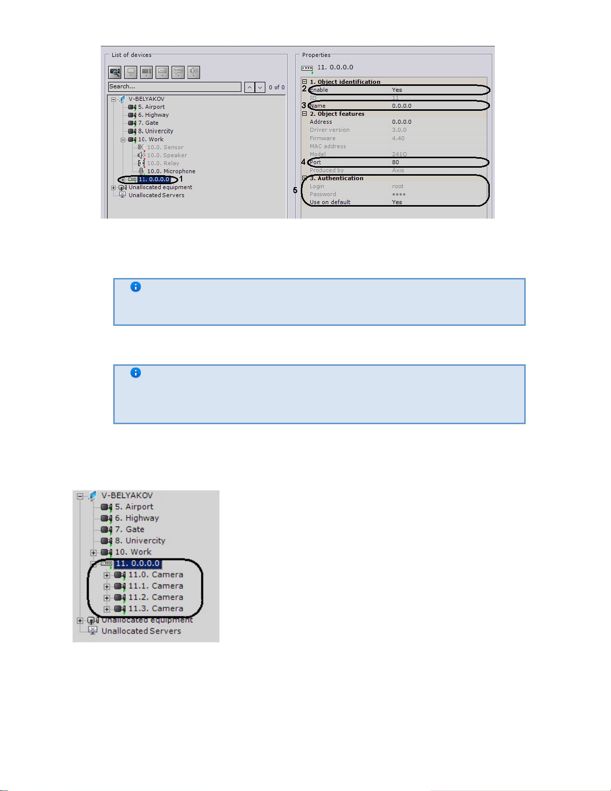
2. Select Yes from the list in th e Enable field to enable the obj ect (2).
eLineTechnology.com
303.938.8062
3. Enter the name of the IP server in the Name fiel d (3).
4. Specify the number of the network port (4). The default value is 80.
Note
5. Set the authentication mode (5)
The port number is initially set through the IP server's web interface
Note
The login and password for connecting to the IP server are set through its
Web interface
6. Click the Apply button.
The IP server and its video cameras will then be enabled, and the icon indicators for the IP server
and video cameras in the objects tree will turn green.
73
Configuration of IP server channels must be performed separately for each channel (with the help
of child objects of Video camera).
The Microphone Object
If a microphone is physically connected to the system independent of a video camera, then you
must specify the video camera to which it will be linked in the settings of the given microphone.
Page 74

When you do this, the Microphone object will become a child of the specified Camera object.
eLineTechnology.com
303.938.8062
Note
This setting is used during synchronized video and audio monitoring of a situation
as well as during synchronized video and video recording to the archive (see the
section Audio Monitoring)
Note
This setting is relevant only for microphones connected to IP servers. The
microphone and the video camera to which it is to be linked must be connected
to the same IP server
If the microphone is embedded in a video came ra or physically connect ed to it, then its
corresponding object will be automatically displayed in the objects tree as a child of that particular
video camera.
To configure the Microphone object, perform the following:
1. Select the Microphone object in the objects tree.
2. Enable the microphone by selecting Yes in the Enable field (1).
3. Enter the name of the microphone in the Name field (2).
4. Configure additional microphone parameters (audio codec, bit rate, etc.) in the Other group
using their descriptions in the interface of the EyStream software package or, for more
detail, in the official reference documentation of the parent video camera.
5. Click the Apply button.
74
Page 75

The microphone will then be switched to its assigned work mode.
eLineTechnology.com
303.938.8062
To check the microphone's operation, you must perform the following steps:
1.
Select the Sound on/off check box in the Summary group.
2.
Provide an audio signal to the microphone.
3.
If the microphone is configured correctly, the audio signal will be transmitted to the server's
speakers. The strength of the incoming audio signal will be displayed on the indicator to the
right of the Sound on/off check box.
Checking microphone operation is now complete.
The Telemetry Object
The Telemetry object displays the characteristics of the PTZ device that should be connected to a
PTZ video camera.
To configure a Telemetry object, perform the following:
1.
Select the Telemetry object in the objects tree
2.
Enable the PTZ device by selecting Yes in the Enable field (1).
3.
Enter the name of the PTZ device (2).
4.
Enable patrol mode. When patrolling is enabled, the video camera automatically changes its
position along a route defined in its presets list
75
Page 76

Note
eLineTechnology.com
303.938.8062
Patrolling is enabled through the Patrolling button in the PTZ camera
control panel (see the section titled Patrolling).
5. Set the interval of time (in seconds) at which the PTZ device will swi tch betwe en presets
while in Patrol mode.
6. Click the Apply button.
The PTZ device will then be switched to its assigned work mode.
To check the functioning of the PTZ device, click the Test button. If the PTZ device is configured
correctly, it will turn one step and return to its original position.
76
The Sensor Object
If a sensor is physically connected to the system independ ently of a video camera, then you must
specify the video camera to which it will be linked in the setti ngs of the given sensor. When you
do this, the Sensor object will appear under the specified Camera object in the object tree.
Note
This setting is used to link alarms initiated by the triggering of a sensor to a
video camera
Page 77

Note
eLineTechnology.com
303.938.8062
This setting is relevant only for sensors connected to IP servers. The sensor and
the video camera to which it is to be linked must be connected to the same IP
server
If the sensor is embedded in a video camera or physically connected to it, then its correspondin g
object will be automatically displayed in the objects tree as a child of that particular video camera.
To configure a Sensor object, perform the following:
1. Select the Sensor object in the objects tree (1).
2. Enable the device (2).
3. Enter the name of th e sensor (3).
4. Set the status to which the sensor will be set when no alarm is present.
5. Click the Apply button.
The sensor will then be switched to its assigned work mode.
The current status of the sensor is displayed in th e Sensor information group.
The Relay Object
77
If a relay is physically connected to the system independently of a video camera, then you must
specify the video camera to which it will be linked in the settings of the gi ven relay. When you do
this, the Relay object will appear under the specified Camera object in the obj ect tree.
Page 78

Note
eLineTechnology.com
303.938.8062
This setting is relevant only for relays connected to IP servers. The relay and the
video camera to which it is to be linked must be connected to the same IP server
If the relay is embedded in a video camera or physically connected to i t, then its corresponding
object will be automatically displayed in the objects tree as a child of that video camera.
To configure a Relay object, perform the following:
1. Select a Relay object in the objects tree.
2. Enable the device (1).
3. Enter the name of the relay (2).
4. Set the status to which the relay will be set when no alarm is present.
5. Click the Apply button.
The relay will then be switched to its assigned work mode.
To check the functioning of the relay, click the Test button. If the relay is configured correctly, its
status will briefly change.
78
Page 79

eLineTechnology.com
303.938.8062
The Speaker Object
The Speaker object is used to configure audio notification, which is launched as an automatic
response when a detection tool is triggered.
In EyStream you can create the following types of Speaker objects:
1. IP speaker device. Created automatically if there is an audio outlet on an IP device.
Note
One audio outlet on an IP device corresponds to one child Speaker of the
2. System speaker. Created manually. Sound on the system speaker is played back using the
server's sound card.
A Speaker object can play audio notification files wi th the extensions:
1. .wav
2. .mp3
3. .mkv
4. .avi
The following audio notification file encoding formats are supported:
1. G.711
2. G.726
3. PCM
The audio notification file should be stored on the computer corresponding to the Server object
on the basis of which the Speaker object is registered.
Camera object
79
Creating an Object
Page 80

To create a Speaker system object, you must perform the followin g steps:
eLineTechnology.com
303.938.8062
1. In the list of devices, highlight a Server object (1).
2. Click the button (2).
3. Click the Apply button.
4. When you do this, the Speaker object appears in the list of devices (3).
Creation of the Speaker object is complete.
Configuring a Speaker Object
To configure a Speaker object, you must perform the following steps:
1. In the list of devices, highlight the Speaker object which needs to be confi gured.
80
2. Select Yes from the list in the Enable fi eld to activate the Speaker object (1).
3. In the Name field (2), enter the desired name of the Speaker object.
4. In the Audio file field (3), enter the full path to the audio notification file.
5. In the Volume fiel d (4), enter the desi red speaker volume l evel.
Note
When configuring the speaker of an IP device, you can set other
parameters as well, such as the compression algorithm for the audio signal
sent to the speaker for playback. Which speaker parameters you can
configure is determined by the protocol for integrati on of the IP device and
the EyStream software package
Page 81

eLineTechnology.com
303.938.8062
6.
Click the Apply button.
Configuration of the Speaker object is now complete.
Checking Audio Notification
To check audio notification from a Speaker object, click the Test button (1).
81
When you do this, the audio notification file whose path you indicated in the corresponding field
plays back (see the section Configuring a Speaker Object). To stop the test playback, click the Sto
p button (2).
The E-mail Object
The E-mail object is used to configure electronic messages which can then be sent to a user as an
automatic response when a detection tool is triggered.
Creating the E-mail Object
To create an E-mail object, you must perform the following steps:
1.
In the list of devices, highlight a Server object (1).
Page 82
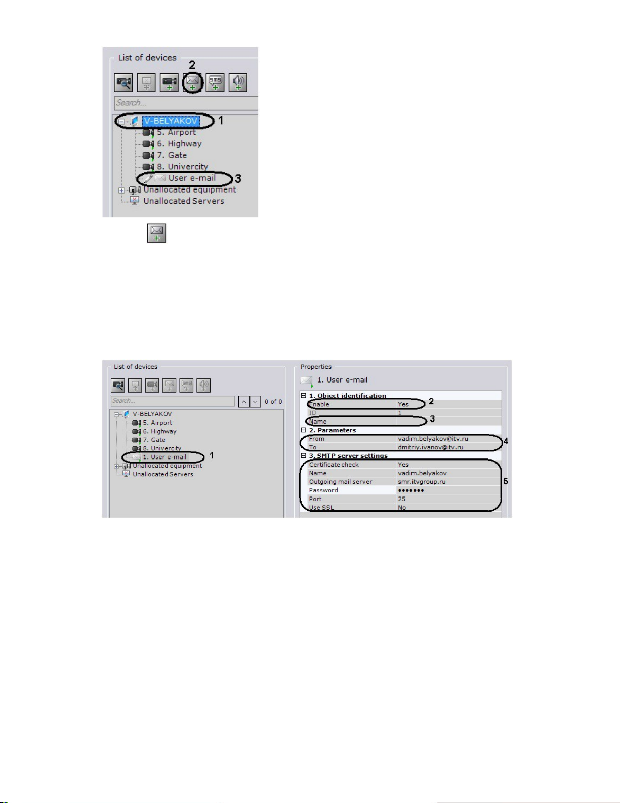
eLineTechnology.com
303.938.8062
2.
Click the button (2).
3.
Click the Apply button.
4.
When you do this, an E-mail object appears in the list of devices (3).
Creation of the E-mail object is now complete.
Configuring the E-mail Object
To configure an E-mail object, you must perform the following steps:
1.
In the list of devices, highlight the E-mail object which needs to be configured (1).
82
2.
Activate the E-mail object (2) by selecting Yes in the Enable list.
3.
In the Name field (3) enter the desired name of the E-mail object.
4.
In the Notification delivery parameters field (4) , set the delivery parameters for the
e-mail message:
a.
In the To field, enter the e-mail address to whic h the messages will be sent.
b.
In the From field, enter the e-mail address from which the messages will be sent.
5.
In the SMTP server settings field (5) , enter the settings of the outgoing mail server:
a.
In the Name field, enter the name of the user account used to send messages on the
outgoing mail server.
b.
If you need to use an SSL-encrypted connection when connecting to the outgoing mail
server, select Yes from the Use SSL list.
c.
In the Password field, enter the password for the user account on th e outgoing mail
server.
d.
In the Port field, enter the number of the port used by the outgoing mail server.
e.
If, when using an encrypted connection, the S SL certificate must be checked, selec t Y
es from the Certificate check list.
f.
In the Outgoing mail server field, enter the name of the outgoing SMTP mail server.
6.
Click the Apply button.
Page 83

Configuration of the E-mail object is now complete.
eLineTechnology.com
303.938.8062
Checking E-mail Notification
To check e-mail notification from an E-mail object, send a test message by cli cking the Test
message button.
When you do this, the following message is sent to the e-mail address indicated in the To field
(see the section Configuring the E-mail Object): "This is a test message to check EyStream
E- mail notification."
Note
If the recipient does not receive th e messag e, make sure that the settings of the
E-mail object have been properly configured
The SMS Object
The SMS object is used to configure SMS messa ges which can then be sent to users as an
automatic response when a detection tool is triggered.
Note
If a USB modem is used to send SMS messages, use the modem utility fr om the
Procedure of configuring SMS notifications
To configure SMS notifications:
1. Stop the Server.
2. Connect a modem and, in the utility supplied with the modem, wait for the signal level to be
3. Make sure that the number of the SMS center is shown. Do not connect to the Internet.
modem software bundle. It will unlock the modem for correct operation
determined.
83
Page 84

4.
eLineTechnology.com
303.938.8062
Start the Server and Client. Create and confi gure an SMS object.
Creating the SMS Object
To create an SMS object, you must perform the following steps:
1.
In the list of devices, highlight a Server object (1)
2.
Click the button (2).
3.
Click the Apply button.
4.
When you do this, the SMS object appears in the list of devices (3).
Creation of the SMS object is now complete.
Configuring the SMS Object
To configure an SMS object, you must perform the following steps:
1.
In the list of devices, highlight the SMS object which needs to be configured (1).
2.
Activate the SMS object (2) by selecting Yes in the Enable list.
3.
In the Name field (3) enter the desired name of the SMS object.
4.
In the To field (4), enter the cellular telephone number, in international format (+<country
code>хххххххххx), to which messages will be sent.
5.
In the SerialPort settings group (5), indicate the port settings used to connect to the GSM
modem by which SMS messages will be sent:
a.
If you need to use a DTR control signal, select Yes from the DTR list.
b.
In the Bits field, enter the number of bi ts in the byte of a data packe t.
c.
In the Stop bits length field, enter the number of bits in the stop bit of a data
packet.
d.
If you need to use a parity check when transmitting data, select th e desired method of
parity check from the Parity list.
84
Page 85

e. From the Port list, select the serial port used to connect to the GSM mod em.
eLineTechnology.com
303.938.8062
f. If hardware control of the serial port data protocol is enabled (see step 5.8) and you
need to use an RTS signal, select Yes from the RTS signal list.
g. Select the speed for data transmission via the GSM modem from the Baud rate list.
h. If you need to control the serial port data protocol, select the desired method of
control from the Handshaking list: hardware (RTS/STS), software (XOn/XOff), or
alternating.
6. Click the Apply button.
Configuration of the SMS object is now complete.
Checking SMS notifications
To check SMS notifications from an SMS message object, send a test message by clicking the Tes
t message button.
85
When you do this, the following message is sent to the mobile number indicated in the To field:
"This is a test message to check EyStream SMS notification."
Note
If the recipient does not receive th e messag e, make sure that the settings of the
SMS object have been properly configured
Configuring the web server
To configure the web server in the EyStream software package:
1. Select a Server object.
Page 86

eLineTechnology.com
303.938.8062
2.
If you want for the web server to start at the same time as the Server in the EyStream sof
tware package, set the Autorun setting to Yes (1). The def ault val ue is Yes.
3.
If you want to disable the web server, set the value of Started to No (2).
4.
In the corresponding fields, enter the user name and password for connecting to the web
server (3).
5.
In the Port field, enter the port number on which the web server will be located (4).
6.
In the Prefix field, enter the prefix that is added to the server address ( 5).
7.
In the Group list, select the group of video cameras that you want to make accessible on
the web server (6).
8.
Click the Apply button.
The web server is now configured and available over the Internet at the following address:
http://<IP address of EyStream Server>:<Port>/<Prefix>. For example, if the server's IP
address is 10.0.11.1, the port is 8000, and the prefix is /asip-api, then the w eb server can be
accessed at the following address: http://10.0.11.1:8000/asip-api.
Configuring detection tools
Types of detection tools
In the EyStream software package, several types of detection tools process incoming data:
1.
Situation analysis detection tools
2.
Basic detection tools:
a.
Video analytics
b.
Audio analytics
3.
Detection tools embedded in a video camera (Embedded analytics):
a.
Video stream processing detection tools
b.
Detection setup takes place using the interface in the Detection Tools tab (under Settings). For
detection setup you must have the appropriate permissions.
Detection tools which process signals from the video camera's sensor
86
Page 87
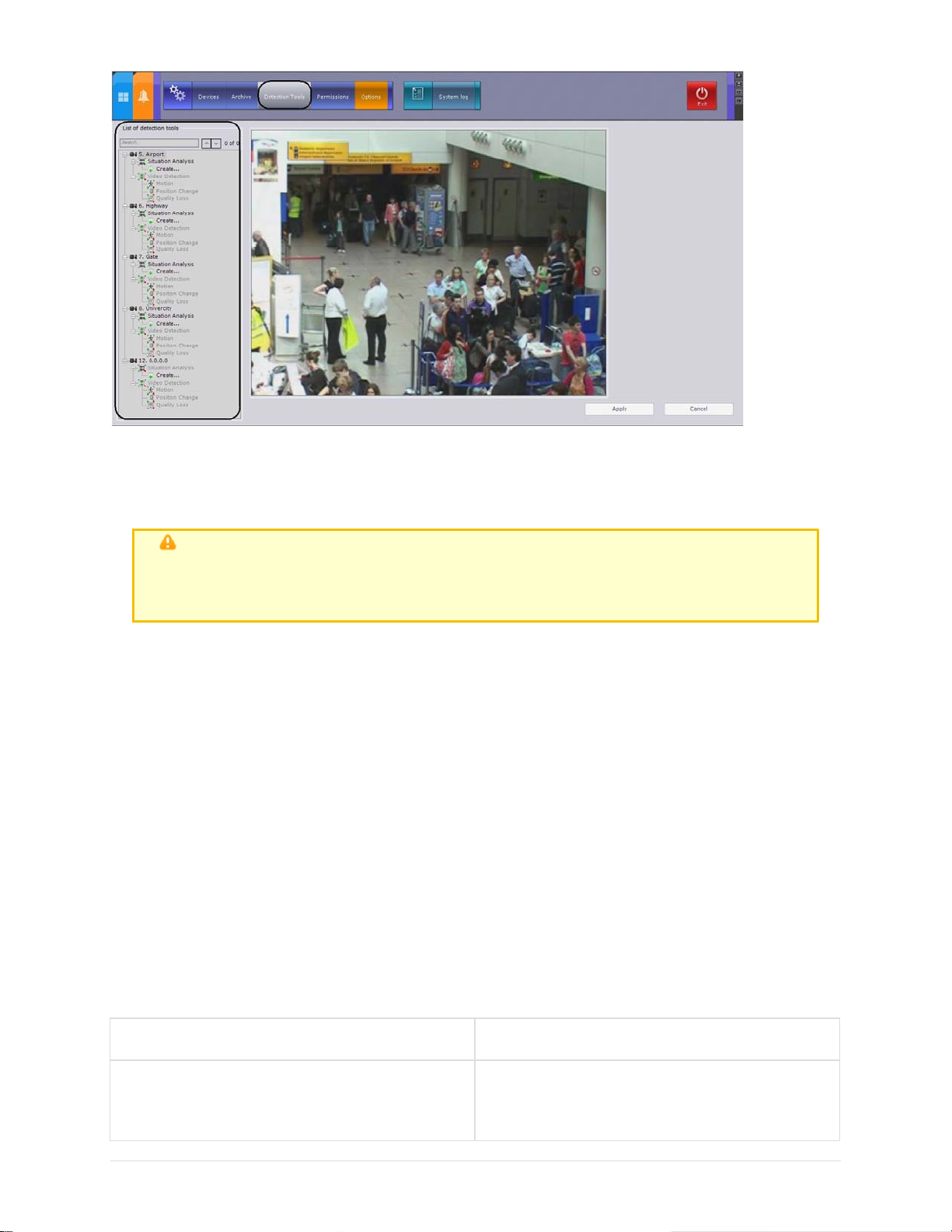
eLineTechnology.com
303.938.8062
The structure of the Detection Tools list consists of three levels:
1. Video cameras
2. Types of video camera detection tools
3. Video camera detection tools
Attention!
For a video camera and its corresponding branch to appear in the Detection Tool s
list, the camera must be enabled in EyStream
Each type of detection corresponds to a parent object:
1. Situation Analysis
2. Video detection tools
3. Audio detection tools
4. Embedded analytics
5. Sensors
Parent objects for those detection tools which can be configured for a video camera are created
automatically depending on the camera's specific ations (see the device's official referen ce
documentation). For example, an Audio Analytics object is created only when there is an audio
outlet on the video camera, and an Embedded analytics object is created only when there are
embedded analytics.
87
Situation Analysis Detection Tools
Types of Situation Analysis Detection Tools
The following detection tools enable analysis of the situation in a video camera's field of view.
Name of a Detection Tool object Detection description
Motion start
a detection tool triggered by the start of
motion in an area of a video camera's field of
view
Page 88

eLineTechnology.com
303.938.8062
Loitering
a detection tool triggered by the lengthy
presence of an object in an area of a video
camera's field of view
Object disappearance
a detection tool triggered by the
disappearance of an object in an area of a
video camera's field of view
Abandoned object a detection tool triggered by the appearance of
an abandoned object in an area of a video
camera's field of view
Line crossing a detection tool triggered by the trajectory of
an object crossing a virtual line
Object appearance a detection tool triggered by the appearance of
an object in an area of a video camera's field
of view
Stopping a detection tool triggered by the cessation of
motion in an area of a video camera's field of
view
Procedure for Configuring Situation Analysis Detection Tools
You can configure situation analysis detection tools as follows:
1.
Enable situation analysis (disabled by default).
2.
Set the general parameters.
3.
Set common detection zones and/or masks.
4.
Create objects for the required types of detection tools.
5.
For each detection tool, set the virtual element (area or line) used for situation analysis.
6.
Set detection parameters (only for loitering detection).
7.
Check detection tool functioning with the help of the Triggers ribbon (optional, see the
section Checking the Triggering of a Detection Tool).
8.
For each detection tool, set rules to be automatically execu ted when the det ection tool is
triggered (see the section titled Configuring Automatic Rules).
88
Enabling Situation Analysis
To enable situation analysis, you must per form the following steps:
1.
In the Detection Tools list, highlight a Situation analysis object (1) which offers a means
of analyzing the situation in the field of view of the required vid eo camera.
2.
Select Yes from the Enable list (2).
3.
Click the Apply button.
Page 89

Note
eLineTechnology.com
303.938.8062
After enabling situation analysis, the viewing tile will display the properties (width
and height as percentages of the width and height of the frame) of tracked
Situation analysis is now enabled.
objects
Setting General Parameters
To set a situation analysis detection tool's general parameters, you must perform the following
steps:
1. In the Detection Tools list, highlight a Situation analysis object (1) which offers a means
of analyzing the situation in the field of view of the required video camera.
2. If you need to enable recording of video stream metadata, select Yes from the Metadata
recording list (2).
3. If you require automatic adjustment of the sensitivity of scene analytic detection tools, in
the Auto Sensitivity list, select Yes (3).
89
Page 90

Note
eLineTechnology.com
303.938.8062
Enabling this option is recommended if the lighting fluctuates significantly
in the course of the video camera's operation (for example, in outdoor
conditions)
4. In the Maximum height and Maximum width fields (4), enter the maximum height and
width of a detectable object as a percent of the height of the video image frame. The values
should be in the range [2, 100].
5. In the Max Rest Time field (4), enter the maximum rest time of an object in secon ds, after
which it is considered abandoned. This value should be in the range [3, 1200].
Note
This setting is relevant for an abandoned object detection tool
Note
6. In the Minimum height and Minimum width fields (4), en ter the minimum hei ght and
width of a detectable object as a percent of the height of the video image frame. The val ues
should be in the range [2, 100].
7. In the Period field (4), enter the time in milliseconds. This is the period of ti me after wh ich
the next video frame will be analyzed. This value should be in the range [ 0, 65535]. If the
value is 0, each frame of the video image is analyzed.
8. In the Sensitivity: motion field (4), set the sensitivity for motion detection tools, on a
scale of 1 to 80.
9. In the Sensitivity: abandoned object field (4), set the sensitivity for situational analytic
tools for abandoned objects, on a scale of 5 to 30.
It is recommended to start by setting the value of this parameter at 10
Note
These parameters depend on the lighting conditions and should be chosen
empirically. It is recommended to start by setting the sensitivity at 20
10.
Click the Apply button.
The general parameters of the situation analysis detection tools are now set.
90
Setting Common Detection Zones
You can set detection zones and masks that are common to all situation analysis detection tools.
Detection zones are analyzed by all situation analysis detection tools.
By default, the entire frame is a detection zone. The detection zone is marked with a dimmed
green background.
If you need to exclude complex zones in the camera fiel d of view from analysi s (leaves, water,
etc.), delete the detection zone in the area. To do this, follow the steps below:
1. In the Detection Tools list, highlight a Situation analysis object (1) that offers a means of
analyzing the situation in the field of view of th e required video camera .
Page 91

2. In the viewing tile (2), set the nodes of the closed area, in order, inside or outside of which
eLineTechnology.com
303.938.8062
you want to delete the detection zone.
Note
When the area is being constructed, the nodes are con nected by a twocolor dotted line which outlines the area's borders
Action Result
Left-click in the viewing tile Creates a new area node
Right-click on a line
Right-click on a created node Deletes the area node
Position the cursor on a node and hold
down the left mouse button while you move
Moves the area node
the mouse
Click the button.
Deletes the area
3. As soon as a closed area is set, the i con bar appears for creati ng and deleting the
detection zone inside or outside the area. To utilize an icon's function, click it with the left
mouse button. Red icons let you delete the detection zone
Icon Executed function
Deletes the detection zone inside the
outlined area
Deletes the detection zone outside the
outlined area
After you delete the detection zone, the selected area is visualized in the viewing tile as an
91
Page 92

area with a dimmed red background.
eLineTechnology.com
303.938.8062
Deletion of the detection zone is now complete. To create a detection zone:
1.
Select a Situation analysis object. Set the nodes of the closed area inside or outside of
which you want to create a detection zone (see steps 1 and 2 in the previous instructions).
2.
Use the green icons to create a detecti on zone.
Icon Executed function
Creates a detection zone inside the outlined
area
Creates a detection zone outside the
outlined area
3.
Click the Apply button.
Creation of the detection zone is now complete.
Creating a Detection Tool object
To activate the needed type of situation analysis detection, you must create the corresponding
object (see the section titled Types of Situation Analysis Detection Tools).
To create a Detection Tool object, you must perform the following steps:
1.
In the branch of the Situation analysis object which offers a means of analyzing th e
situation in the desired video camer a's field of view, click Create.
92
2.
Highlight the Select detection type link which appears (1).
Page 93

eLineTechnology.com
303.938.8062
3. Click the Apply button.
Creation of the Detection Tool object is now compl ete.
Setting Virtual Elements
Line
Area
On page:
For each type of situation analysis detection tool you must set a virtual element of one of two
types:
1. A line
2. An area
Attention!
If no visual element is set, th e detection tool will not work
The type of visual element is determined by the detection type. Only the Line crossing detection
requires you to set a Line element. Other situation analysis detection tools requi re you to set an
Area element for each detection tool.
Line
The Line visual element sets a virtu al line in the field of view of a video cam era; when something
crosses this line, it triggers the Line Crossing detection tool.
To set a line, you must perform the following steps:
1. In the list of detection tools, highlight a Line Crossing object (1).
93
Page 94

2. In the viewing tile (2), set the endpoints of the line which, when intersected, will trigger
eLineTechnology.com
303.938.8062
Line Crossing detection.
Note
When the line is being constructed, the end poin ts are connected by a
two-color dotted line. The direction of the object's motion across the line is
indicated by dotted arrows (2
Action Result
Left-click in the viewing tile Creates a line end point
Position the cursor on an end point and,
holding down the left mouse button, move
Moves the line end point
the mouse
Click the button
Deletes the line
3. By default, Line Crossing detection monitors object motion across the line in both directions.
To suspend detection of motion in one direction, click the button corresponding to that
direction.
Attention!
At least one direction must be selected for detection
Note
4. Click the Apply button.
The line is now set.
Area
The Area visual element sets an area of a video camera's field of view, in which the situation is
analyzed by a detection tool of the selected type.
To set an area, you must perform the following steps:
1. In the Detection Tools list, highlight the Detecti on Tool object for which you need to set an
An unmonitored direction of object motion is indicated by a dimmed arrow
94
Page 95

area (1).
eLineTechnology.com
303.938.8062
2. In the viewing tile (2) set the nodes of the area, in order, in which the situation requires
analysis.
Note
When the area is being constructed, the nodes are connected by a twocolor dotted line which outlines the area's borders
Action Result
Left-click in the viewing tile Creates a new area node
Right-click on a created node Deletes the area node
Position the cursor on a node and hold
down the left mouse button while you move
Moves the area node
the mouse
Click the button
Deletes the area
3. Click the Apply button.
The area is now set.
Settings Specific to Loitering Detection
When configuring the Loitering detection tool, you must set the maximum time an object can be
in the analyzed area: when the maximum time i s exceeded, the detecti on tool is triggered.
To set a maximum time, you must perform the following steps:
1. In the Detection Tools list, highlight a Loitering object (1).
95
Page 96

2. In the Maximum loitering time field (2), enter the maximum object loitering time in
eLineTechnology.com
303.938.8062
seconds. This value should be in the range [0, 3600].
3. Click the Apply button.
The maximum loitering time is now set.
Video Analytic
Types of Video Detection
The following detection tools enable analysis of the video image from a camera.
Name of a Detection Tool object Detection description
Loss of quality a detection tool which is triggered when the
video image received from a video camera
loses quality
Motion
a detection tool triggered by motion in a video
camera's field of view
Position change
a detection tool triggered by a change in the
video image background indicating a change in
the video camera's position in space.
Procedure for Configuring Video Detection
For each video camera, video detection tools of all three types are automatically created (see th e
section titled Types of Video Detection).
You can configure video detection tools as follows:
1. Enable video detection (disabled by default).
2. Set the general video detection tool properties.
3. Enable the desired video detection tools (all are disabled by default).
4. Configure the motion detection.
Note
The loss of quality and position change detection tools do not require
configuration
5. Check detection tool functioning with the help of the Triggers ri bbon (optional) (see the
section Checking the Triggering of a Detection Tool).
6. For each detection tool, set rules to be automatically executed when the detection tool is
triggered (see the section titled Configuring Automatic Rules).
96
Enabling Video Detection
To enable video detection, you must perform the following steps:
Page 97

1. In the Detection Tools list, highlight a Video Detection Tool object which offers a means
eLineTechnology.com
303.938.8062
of analyzing the video image from the desired video camera.
2. Select Yes from the Enable list.
3. Click the Apply button.
Video detection is now enabled.
The desired video detection tools may be enabled in the same way as video detection.
Setting General Parameters of Video Motion Detection
To set the general parameters of video detection tools, you must perform the following steps:
1. In the Detection Tools list, highlight a Video Detection Tools object (1) which offers a
means of analyzing the video image from the desired video camera.
2. If it is necessary to decode frames every 500 mil liseconds or less often, in the Decode
keyframes list, select Yes (2).
Important
This setting applies to all codecs. If a codec has keyframes and p-frames,
the keyframe is decoded no more often than every 500 miliseconds.
This feature reduces the Server load but, as can be expected, negati vely
impacts the quality of detection.
This setting should be activated on "blind" Servers (Servers that do not
display video) on which it is necessary to perform detection.
97
Page 98

3. In the Period field (3) enter the time in milliseconds after which the next video image
eLineTechnology.com
303.938.8062
frame will be processed. This valu e should be in th e range [0, 65535 ]. If the valu e is 0,
each frame of the video image is processed.
4. Click the Apply button.
Setting the general parameters of the video detection tools is now complete.
Settings Specific to Video Motion Detection
To configure VMD, you must perform the following steps:
1. In the Detection Tools list, highlight a Motion object (1).
2. In the Sensitivity field: contrast (2) , enter the sensitivity of the detection tool to object
contrast. You should select a value empirically in the range [0, 16]. The greater the value,
the less contrastive the objects which can be detected.
3. In the Sensitivity field: size (2), enter the sensitivity of the detection tool to object size.
You should select a value empirically in the range [0, 10]. The greater the value, the smaller
the objects which can be detected.
4. In the viewing tile, set detection zones and/or masks in the same way as for situation
analysis detection tools (3).
Note
5. Click the Apply button.
VMD configuration is now complete.
See steps 2–4 in the section Setting Common Detection Zones
98
Audio analytics
Types of Audio Detection
The following detection tools enable analysis of the audio signal from a microphone.
Name of a Detection Tool object Detection description
No signal
Signal A detection tool which is triggered by the
A detection tool which is triggered by the
absence of an audio signal from an audio
device
reception of an audio signal from an audio
device
Page 99

Noise A detection tool which is triggered by the
eLineTechnology.com
303.938.8062
appearance of noise
Attention!
No Signal audio detection may operate incorrectly with video cameras emitting a
background signal with a non-zero volume, even if the integrated microphone is
physically disabled
Procedure for Configuring Audio Detection
For each video camera equipped with one or more audio ports, audio detection tools of all three
types are automatically created (see the section titled Types of Audio Detection).
You can configure audio detection tools as follows:
1. Set the general audio detection parameters.
2. Enable the desired audio detection tools (all are disabled by default).
3. Configure the Noise and Sign al detection tools .
Note
4. Check detection tool functioning with the help of the Triggers ri bbon (optional) (see the
section Checking the Triggering of a Detection Tool).
5. For each detection tool, set rules to be automatic ally executed when the detection tool is
triggered (see the section titled Configuring Automatic Rules).
The No Signal detection does not require configuration
99
Enabling Audio Detection
To enable audio detection, you must perform the following steps:
1. In the list of detection tools, highlight the necessary audio detection tool (1).
2. Select Yes from the Enable list (2).
3. Click the Apply button.
Page 100

The audio detection tool is now enabled.
eLineTechnology.com
303.938.8062
Setting General Parameters of Audio Detection
To set the general parameters of audio detection tools, you must perform the following steps :
1.
In the detection tool list, highlight an Audio Detection object (1) which offers a means of
analyzing the audio signal from a microphone connected to the desired video camera.
2.
In the Period field (2), enter the time in milli seconds after which th e next section of th e
audio stream will be processed by the audio detection tools. This value should be in the
range [0, 65535]. If the value is 0, each section of the audio stream is processed.
3.
Click the Apply button.
Setting the general properties of the audio detection tools is now complete.
Settings Specific to the Signal and Noise detections
To configure the Signal and Noise detection tools, you must perform the following steps:
1.
In the Detection Tools list, highlight a Signal or Noise audio detection.
2.
Enter the following values in the Level field:
a.
When configuring the Signal detection tool, enter the audio signal level in standard
units above which the detection tool will be triggered. You should select a value
empirically in the range [0, 1000].
b.
When configuring the Noise detection tool , enter the noise level in standard units
above which the detection tool will be triggered. You should select a value empirically
in the range [0, 1000].
3.
Click the Apply button.
Configuration of the Signal and Noise detection tools is now complete.
100
Embedded Analytics
At the moment of writing of this documentation, the embedded analytics of Axis and Sony video
cameras and Stretch cards have been integrated into the EyStream software package (if they
support it; see the official reference documentation for these devices).
 Loading...