

Page 1

ETV System Server Software
7.00.0000
User Guide
March 2012 Revision
Page 2

A
A
S
Table of Contents
A
A
E
A
A
A
A
A
A
A
S
1
INTRODUCTION
2 SOFTWARE FEATURES............................................................................................................................................7
.........................................................................................................................................................6
3 MAIN SCREEN............................................................................................................................................................8
3.1 LIVE VIEWER
3.2 CAMERA LAYOUT AND QUICK
3.3 TV O
3.4 LIVE VIEWER DISPLAY CONTROLS .........................................................................................................................14
3.5
3.6 MEDIA DRIVE INFORMATION
3.7 PTZ CAMERA
3.8
EARCHING ................................................................................. ............................................................................21
4
4.1 SEARCHING
Video Search
4.2 SEARCHING POS/ATM
UTPUT SWITCH
LARMS AND RELAYS
LIVE POS / ATM DATA
........................................................................................................................................................11
CCESS ...................................................................................................................12
.............................................................................................................................................13
............................................................................................................................................14
..................................................................................................................................15
C
ONTROLS
......................................................................................................................................16
.........................................................................................................................................19
V
IDEO
................................................................................................................................................22
Results
................................................................................................................................................23
D
ATA ................................................................................................................................24
Search for Line Items ................................................................................................................................................24
Search for
4.3 C
4.4 V
Transaction
USTOM SEARCH .................................................................................................................................................26
IDEO PLAYBACK..................................................................................................................................................27
..............................................................................................................................................25
Controlling Playback Video with Digital PTZ: ............................................................................................................28
Menu:
Camera Right-click
Playback
4.5 M
4.6 A
Buttons:
ULTI-SCREEN PLAYBACK
DVANCED FEATURES ..........................................................................................................................................30
......................................................................................................................................................28
.........................................................................................................................................28
....................................................................................................................................30
Smart Search.............................................................................................................................................................30
Zoom..........................................................................................................................................................................32
Image
Adjust
Markers
Audio
4.7 FRAME
4.8
4.9 O
UTHENTICATING RECORDED VIDEO......................................................................................................................34
..............................................................................................................................................................32
......................................................................................................................................................................33
Playback
N-SCREEN DISPLAY - POS/
..........................................................................................................................................................33
DE-I
NTERLACING
.......................................................................................................................................34
TM DATA ...............................................................................................................35
5
XPORTING..............................................................................................................................................................37
5.1 EXPORTING, PRINTING, OR EMAILING IMAGES ........................................................................................................37
5.2 EXPORTING
5.3 EXPORTING
5.4 EXPORT FILE
5.5
5.6 PREVIEW
5.7 SUPPRESS
5.8 SEARCH
6 REPORTS
LARMS
6.1 CLIENT CONNECTIONS
6.2 N
6.3 A
7 VIDEO AND AUDIO RECORDER
7.1 VIDEO RECORDER
7.2
ETWORK LOG ANALYZER
UDIT LOG ANALYZER
UDIO RECORDER CONTROLS
7.3 LIVE
7.4
8
CHAT
SETTINGS – CAMERA SETUP TAB......................................................................................................................50
ETV System
V
IDEO
................................................................................................................................................38
UDIO
................................................................................................................................................40
B
ROWSER
........................................................................................................................................40
...............................................................................................................................................................42
LARMS
.................................................................................................................................................43
LARMS
..............................................................................................................................................43
LARMS
..................................................................................................................................................44
.................................................................................................................................................................45
..........................................................................................................................................45
....................................................................................................................................45
...........................................................................................................................................45
CONTROLS .......................................................................................................46
C
ONTROLS ...............................................................................................................................46
...............................................................................................................................47
UDIO SETTINGS
...........................................................................................................................................48
...................................................................................................................................................................49
Server Software - User’s Guide Page
2
Page 3

Settings ......................................................................................................................................................................51
Advanced
Push Still Shot to
8.1 CODEC
AZTECH CODEC
MPEG4 CODEC
Hardware CODEC
8.2 N
DVR Network Camera
ONVIF and PSIA Network Camera Types
Multiple Cameras Stitched Together Into One
USB
8.3 R
Recording Modes
Scheduled
Motion Recording Settings
Video Motion Alarm
Video Motion Alarm Advanced
8.4 C
Advanced
8.5 V
Video Loss
Video Loss Trigger
Video Loss Email
8.6 A
8.7 L
9 SETTINGS - VIDEO ANALYTICS
9.1 VIDEO ANALYTICS CALIBRATION
Settings.....................................................................................................................................................51
Server............................................................................................................................................52
S
ETTINGS
...............................................................................................................................................53
Settings ............................................................. ......................................................... ..................54
Settings ..........................................................................................................................................55
Settings .......................................................................................................................................55
ETWORK CAMERA SETTINGS
...............................................................................................................................56
Type ......................................................................................................................................57
................................................................................................................58
Image .................................................................... ...........................58
Camera..............................................................................................................................................................59
ECORDING MODE TAB
........................................................................................................................................59
......................................................................................................................................................59
Recording ......................................................................... .......................................................................60
........................................................................................................................................61
...................................................................................................................................................62
Settings ....................................................................................................................63
AMERA CONTROL TAB
........................................................................................................................................66
Settings.....................................................................................................................................................66
IDEO LOSS TAB
..................................................................................................................................................68
Mode .......................................................................................................................................................68
....................................................................................................................................................68
Notification ....................................................................................................................................68
UDIO TAB
IVE OVERLAY TAB
...........................................................................................................................................................68
...............................................................................................................................................69
TAB ....................................................................................................................70
............................................................................................................................71
General ......................................................................................................................................................................71
Perspective
Object Type
Mask
Obstacle Settings
Engine S et tin gs
Display Options
Meta
Settings ..................................................................................................................................................71
...............................................................................................................................................................72
Settings ........................................................... .................................................................................................72
......................................................................................................................................................73
.........................................................................................................................................................74
.........................................................................................................................................................75
Settings.............................................................................................................................................................76
Preview ......................................................................................................................................................................76
9.2 V
IDEO ANALYTICS RULES
People
Counting ........................................................ ................................................................................................78
Camera
Placement ............................................................... ...................................................... ...........................78
People Counting Single
People Counting Multiple
Transaction with No Customer
Camera
Placement ............................................................... ...................................................... ...........................83
Customer Not Present
Queue Analytics
Camera
Time i n Qu e ue
........................................................................................................................................................85
Placement ............................................................... ...................................................... ...........................85
Rule ...............................................................................................................................................86
Time in Queue, Directional Exit
Number of People in Queue Rule
10 SETTINGS - DVR SETTINGS
10.1 GENERAL
Audit ..................................................................................................................................................................94
User
10.2 S
10.3 L
10.4 S
10.5 C
TARTUP TAB
IVE TAB
EARCH TAB
AMERAS TAB
TAB...................................................................................................................................................93
...................................................................................................................................................97
..........................................................................................................................................................98
.....................................................................................................................................................99
..................................................................................................................................................99
......................................................................................................................................78
Tripwire............................................................................................................................79
Tripwire ......................................................................... ................................................82
Present.....................................................................................................................83
Rule ...................................................................................................................................83
Rule .....................................................................................................................87
Settings ............................................................................................................90
TAB.......................................................................................................................92
ETV System
Server Software - User’s Guide Page
3
Page 4

10.6 C
10.7 S
10.8 H
10.9 P
10.10 H
11 SETTINGS - MEDIA DRIVES TAB
LIENTS TAB
EQUENCE TAB
ARDWARE TAB
ROXY TAB
ELP MENU TAB
11.1 VIDEO STORAGE
11.2 U
11.3 D
11.4 A
11.5 E
12 SETTINGS - COM PORTS
13 SETTINGS - USER AND GROUP MANAGEMENT
SING A VIRTUAL FILE SERVER FOR VIDEO STORAGE
ATA PARTIT IO N ING FOR VIDEO AND POS/ATM ALARM VIDEO FOOTAGE
LTERNATE VIDEO STORAGE DRIVES
XPORT DESTINATIONS
13.1 USERS
G
13.2
14 SETTINGS - RELAYS/ALARMS TAB
Input
Settings
ROUPS
Number ...........................................................................................................................................................111
Tab.............................................................................................................................................................111
Client Connections Tab
Notification Settings
Notification ............................................................................. ....................................................................112
Email
Output
Relay ........................................................................................................................................................112
Notification Settings
Remo te Cli e nt Ret ry
Output Relay
15 SE TT IN GS - DATA TA B
POS/ATM Terminal Settings
POS/ATM Settings
Priority Came ra
Terminal Connection Settings
POS/ATM Alarm
Settings... .............................................................. ......................................................................................115
Filter
15.1 G
ENERAL SETTINGS TAB
Live / Playback Settings
Data Storage Settings
POS Search Hi st ory
..................................................................................................................................................100
..............................................................................................................................................100
..............................................................................................................................................101
....................................................................................................................................................102
.............................................................................................................................................103
.....................................................................................................................104
D
RIVES
.................................................................................................................................105
.......................................................................................105
..........................................................106
...............................................................................................................107
...................................................................................................................................107
TAB..........................................................................................................................109
TAB ...................................................................................110
...........................................................................................................................................................110
.........................................................................................................................................................110
................................................................................................................111
...........................................................................................................................................112
Tab..........................................................................................................................................112
.............................................................................................................................................112
Settings ............................................................. .....................................................................113
Settings..............................................................................................................................................113
.....................................................................................................................................114
...................................................................................................................................114
..................................................................................................................................................114
Settings ......................................................................................................................................114
.................................................................................................................................115
Settings ........................................................................................................................................115
.................................................................................................................................116
..........................................................................................................................................116
.............................................................................................................................................116
................................................................................................................................................116
V-POS......................................................................................................................................................................116
15.2 E
15.3 I
15.4 E
15.5 E
16 SETTINGS - AUDIO
MAIL SETTINGS TAB
GNORE FIELDS TAB
XTERNAL POS/ATM DATA TAB
XTERNAL DATA INTERFACE TAB
Audio Recording Device
Audio Talk Device
Live Audio
Settings ..................................................................................................................................................120
Audio Storage
Audio Talk /
17 DV
18
19 UPDATE SERVICE
PLAYER.........................................................................................................................................................121
REGISTRATION ..................................................................................................................................................123
Settings......................................................................................................................................120
Drives...............................................................................................................................................120
Chat ....................................................................... ..............................................................................120
19.1 UPDATE SETTINGS
......................................................................................................................................117
........................................................................................................................................117
.....................................................................................................................118
.....................................................................................................................118
TAB ....................................................................................................................................119
Settings ............................................................................................................................119
.............................................................................................................................................124
T
AB
...................................................................................................................................124
ETV System
Server Software - User’s Guide Page
4
Page 5

19.2 U
19.3 U
20 LANGUAGE
21 DVR SYSTEM DATABASE
PDATES TAB
PDATES LOG TAB
21.1 DRIVE MANAGEMENT
21.2 D
21.3 D
21.4 D
22 SETTINGS UTILITY
23 DVR BACKUP UTILITY
ATA MANAGEMENT TAB
ATABASE MANAGEMENT TAB
ATABASE SETTINGS TAB
24 CONTACT
.................................................................................................................................................126
..........................................................................................................................................126
SWITCHER ............................................................................ ........................................................127
TAB................................................................................................................................128
............................................................................................................................................133
......................................................................................................................................134
INFORMATION .................................................................................................................................135
UTILITY ..................................................................................................................128
.................................................................................................................................129
.........................................................................................................................130
...............................................................................................................................131
ETV System
Server Software - User’s Guide Page
5
Page 6

1 Introduction
This guide
User’s
describes the operation
Guide is
current to Version 6.00.0005
VIGIL Serve r
features. It’s
unlimited flexibility for the advanced
is
cutting
intuitive
edge
design
digital
provides
of
eLine’s Server Software (VIGIL Server).
video
ease of use
.
of VIGIL
recording software with
Server.
for the most
basic
an
user
This
version of
abundance
while
providing virtually
the
of empowering
ETV System
Server Software - User’s Guide Page
6
Page 7

2 Software Featur
section describes
This
Feature
Individual Camera
Settings
Configurable
CODEC
Settings
IP
Camera Support
Live Viewer
Built-in Playback
Full Video Search
C
apab
ilities
Exporting/Saving
Video and Images
some of
Configure
and more.
Change CODEC
and more.
VIGIL Server supports up
capture card.
View live footage
Scan
Retrieve a list
d
ate/time and a
Powerful export capab
(MJPG) formats.
es
the features
each
camera independently: brightness, contrast, sharpness, hue, resolutions,
settings for
as
previously recorded footage
of stored footage
variety of other search criteria.
Save still
of VIGIL
each
to
32 IP hi-resolution cameras without the
it records for
ilities
enable you
shots
Server.
Details
camera
up
using
for specified cameras from
in JPEG
such as
to
32 video feeds.
the built-in
to
save video footage
or
BMP formats.
compression, quality,
video player.
noise reduction
need
for
an installe
a
start date/time
in AVI or Authentic Video
to
an en
,
d
d
ETV System
Server Software - User’s Guide Page
7
Page 8

3
Main Screen
the
This is
Main
automatically
changed
in
the settings,
Screen window that
load
at Windows start-up,
if desired.
is
displayed
log on a nd open
when VIGIL
the
Server
Live
has
finished loading.
Viewer window.
These
The
program will
options
can be
Icon Toolbar:
table
This
outlined
is a quick
in
later sections.
ETV System
listing
Exits the VIGIL
This will cause VIGIL
Logs
logged off.
Opens
of
the
main
toolbar buttons
Server program.
Server to
off the current user. VIGIL
the
Recorder Controls window.
Server Software - User’s Guide
and
Click Yes in
stop
recording
Server
their usage. Detail
the Exit Confirmation window to exit VIGIL Server
video footage.
will continue to record
of each
corresponding window is
video footage
while
.
the user is
8
Page 9

Opens
the
Audio
The
button
Opens
If
Hardware Rendering
clicked.
Time Cams.
Opens
Clicking the button
window.
R
esets the windows to their d efault positions.
Clicking the button
Alarms, Export
Connections,
The
button
Live POS Data
replace the reset
Opens
Opens
remaining, registration information
ver
sions).
A basic
mouse
window.
Main
Menu Toolbar:
Main menu
or Hardware Information via
window expands
following features are
The
Live POS/ATM
Export Fil
Browser
Reset Windo
Positions
Multiplexer Setup
options includ e window viewing features
on
the functions
Displays
Data
Alarms
Analog
Lists
e
as: Point
alarm events
Displays a thumbnail browser interface to the export destinations.
w
R
esets
Opens
the
Live Audio
Recorder Controls window
changes
the
Live
Viewer window.
This opens a
the Search window.
File
and
changes
is
the Settings window.
the About
graph that l ets
cursor over this section to
the
Help menu
in
accessible by
a live
viewer of received data.
of Sale,
all
windows to their original
the
Analog Out Multiplexer window.
Settings window. Clicking the button
its
icon and
has been
context
opens
opens
Browser, Reset
User Audit.
its
selected, not
icon
with the
ETV
icon and
icon
This is
DVR
you kno w how
System window that contains information
item. Addi ti on all y, the
the
icon toolbar.
ATM
and
clicking
or
thumbnails;
on
Access Control.
opens
can be opened.
function to t he
enabled
menu
allowing selection of either Software Rendered
the context
the context
Windows Positions,
function to the
only would
for the
the
main
and
the software version (including IP Camera
many client connections are
view
via
the Windows
last used audio window
and is supported by
menu which allows you
menu which allows you
Analog
last used
it
open
Live POS Data window.
configuration
the
exact
tool item.
the
Live POS Data window, but it
page
number or
menu
the ca pture card , the butto n
item
the context
.
to
to
Multiplexer Setup, Sequence, Clien
For example, if
for VIGIL Server.
open
click
to
and access
Tools menu i n
ns.
:
from
any supported data source such
the
Tools menu item
This data
allows you
sizes and locatio
to replay footage from the time of the event.
can come
menu
from whi
can be
Cams
or Real
open
the Custom Search
open Live POS/ATM Data
is clicked an
would also
such as
to VIGIL
open
the Client Connection
the trial period
and POS
Server. Hover th
.dll fil
to the User Guid
the
main VIGIL Server
ch
,
t
d
e
e
s
e
Page
ETV System
Server Software - User’s Guide
9
Page 10

Sequence
Enables and
Client Connections
Video Analytics
Repor
User Audit Report
Recorder
Settings
Network Log
Analyzer
Audit Log
Analyzer
V-POS
Update…
Automati
Updates
Register DVR Opens
t
Opens
c
disables a configured camera sequence
Lists client systems
Counters
Alarms
POS
Opens
the User Audit features, it must
Opens
Opens
network.
Opens
VIGIL Server.
Provides
especially usefu l if VIGIL is
Opens
applicatio
Opens
the User Audit Report window whe re configured
the Recorder Controls window.
the Settings window
the Network
the Audit
a quick way
the
Local Update
ns.
the Update
the Registration
currently connected to the DVR.
For rules where data
For rules where alarm conditions
For
rules where register regions are configured, the register counts are exported.
Log
Log
Analyzer,
to
Service window
window to
be
configured
.
Analyzer,
load
configured for
Utility that provides
used
to display history of functions performed
used
to display
the application if the V-POS
Kiosk mode
.
allow you
.
Opens a
range for
POS
click
format to a Windows destination.
show
analytics
rule type, time,
is
counted, entries with count
in
the settings window.
a log
where the Windo ws Start
a small
to register the VIGIL software.
program to perform software updates for DV
window where the user selects
a Video Analytics Counters, Alarms or
report.
the Export button to
results recorded for certain types of vide
are configure d, the a lar m s ar e exported.
usage
of
When
the range
rules including the camera number
and object count.
monitoring
any
information, warnings or errors from
software program
has been selected
save
the report
logs
are exported
can be
reviewed.
by
is
menu is disabled.
a time
in CSV
The
report will
.
To us
users over th
installed. It is
,
o
,
e
e
R
Page
ETV System
Server Software - User’s Guide
10
Page 11

3.1 Live Viewer
The Live
settings,
Graphics Adapter
Viewer window
you
must
log on
intensive function.
will open
before the
automatically
Live
Viewer window
once
the program
has
loaded.
is
opened. Note: The Live
If Auto
Logon is
Viewer
disabled
in th
is a CPU an
e
d
The Live
capture card supports Hardware Rendered mode, it
Settings tab | Live
Viewer window
Software
Rendered
Hardware
Rendered
Note:
The Live
tab
can be in
and selecting
• Requires more
• Camera display
•
Able
•
Able
• Information overlays
• Zooming displayed camera f eeds
•
Able
•
Less CPU usage.
•
Able
• Cannot display information overlays.
• Cannot
Viewer window
installed, the rendering
channels.
either Sof t wa re Rend er ed
the
Live
Viewer
CPU usage.
speed
to display
to display network camera feeds.
to display
to display network camera feeds.
zoom
mode
up
up
displayed camera feeds.
enabled (hardwar e vs. soft ware)
depends
to
32
such as
to
32
may be
camera feeds.
recording status
camera
slightly different depending
mode
can be
mode
on CPU and video
and
other available camera manipulation features.
analog feeds.
enabled
with the available radio button.
and video analytics data.
or Hardwa re Rendered mod e.
by going
card ab
and
ilities
on
the number
to Settings window | DVR
the capture card that is
of
supported vide
If your
o
Page
ETV System
Server Software - User’s Guide
11
Page 12

3.2 Camera Layout and Quick
Use
the buttons
cameras enabled than
select a page of
in
the top section of
can be
displayed
cameras to display.
the
Live
by
the current
Software
Single vie w mode
5
(25 cameras),
Rendered
6 x 6
mode
(1 camera),
(36 cameras). 2 large w/8 small
Hardware Rendered
To
quickly
Camera
status of
select a
Quick Access
each
Green: Constant
mode
camera for
camera,
recording
pad. Camera
which is communicated through color:
Blue: Motion
recording
mode and is
Red: Alarm reco rding
mode and is
Yellow: Set
stop
after the
Uncolored:
to a motion recording
Post Motion
Camera
is
currently not recording, but
Disabled:
To
arrange the cameras within the current
window
more than
and select
one
location,
a
camera to
if you selected
new location.
Camera
is
not recording
be
displayed from t he context menu .
a
camera that
To
remove a camera from the
Live
Viewer window, right-click that particular camera
Note: Stopping or changing camera
settings.
feeds in
When in
Software Rendered mode, right-click a camera
Copy
Full Screen
Quick Search
Copies
Enlarges
Note:
click.
Plays
M
Zoom
Opens
OSD
the current
the
To zoom in on an image in Full Screen
To zoom
recent footage for the selected camera
inutes before the current time
the
zoom
Enable On-Screen
Display
Configure
video image
live video
out
OSD Opens
feeds to fill the entire
on an
image,
control. Left-click
Enable On Screen
camera
Access
Viewer
for
32
channel systems
2 x 2 mode
viewing options
Single Live View
mode and is recording.
Record
view
style, right-click
the
to the Windows clipboard.
hold down
.
on an image
is
the
side
toolbar to select the viewing style.
view
settings,
(4 cameras),
vary
Quick Access also
recording (motion detected).
recording (alarm triggered).
mode and is
time
has elapsed).
and is disabled.
is
already displayed, it
Live
Viewer window
feed
to
PC window.
the Control key and right-click.
in
Display of
configured
OSD Configuration
If
you can
has th
ese available viewing options:
3 x 3
cameras, 1 large w/12 small cameras.
based on
display mode,
provides a simple
recording (motion currently not detected
is enabled.
on a
right-click
(9 cameras),
the system model.
click
its corresponding number
on
4 x 4
way
camera position
Since you cannot
will move
the camera
the layout
(16 cameras), 5 x
to
check
in
display a camera in
feed and select Stop.
does
not affect the recordin
view
the fol lowing options:
mode,
as a POS Priority Camera.
hold down
the
Playback window; select
to
zoom in and
POS
Window.
the keyboard Control key and left
right-click to
Data.
This
See
section 4.9 for details.
from One, Five, or Ten
zoom out.
option
will be
you have more
icon an
in th
the recordin
and will
the
Live Viewer
feed
to th
g
available if th
d
e
g
e
-
e
Page
ETV System
Server Software - User’s Guide
12
Page 13
Stop
Stops the
Reset to Default R
esets
all
Camera Control
Digital PTZ
Relays
# -
Camera
3.3
With supported hardware, VIGIL
Multiplexor support
analog
for details.
outputs
Opens
Enable
the
default for
Interfaces
open states respectively.
Changes
display, it
the Camera Control pad
Digital
PTZ
TV Output Switch
and
can be
multiplex
configured
Note: Capture Card
DVR200X, DVR100X,
PROSERIES
Types
with multiplex
output with
–
support
The TV
number. If
camera number.
On
systems supporting Mux/Analog Out,
item,
which opens
video
feed from
cameras to their default position for the current camera layout.
PTZ
to
control to
all
cameras that
to the configured relays.
the current
will move
Server
analog
outputs varies between models; please check
DVR50X – one
single
output cards are available for
Output Switch c hang es
no
monitors are selected,
the
being
displayed, but
that
allows
use PTZ
pan and
video
the camera feed to the
can
as a
analog
control features within a fixed camera image.
tilt within the fixed image.
do
not
have
alternative camera control setup
Relays can be toggled
feed
on
the selected camera.
display a number
multiplexed
video
output features available include:
does
not
stop recording.
users to control
new location.
PTZ cameras.
This
on
If that
of video fe eds
output similar to the
monitor output with multiplex support
camera support
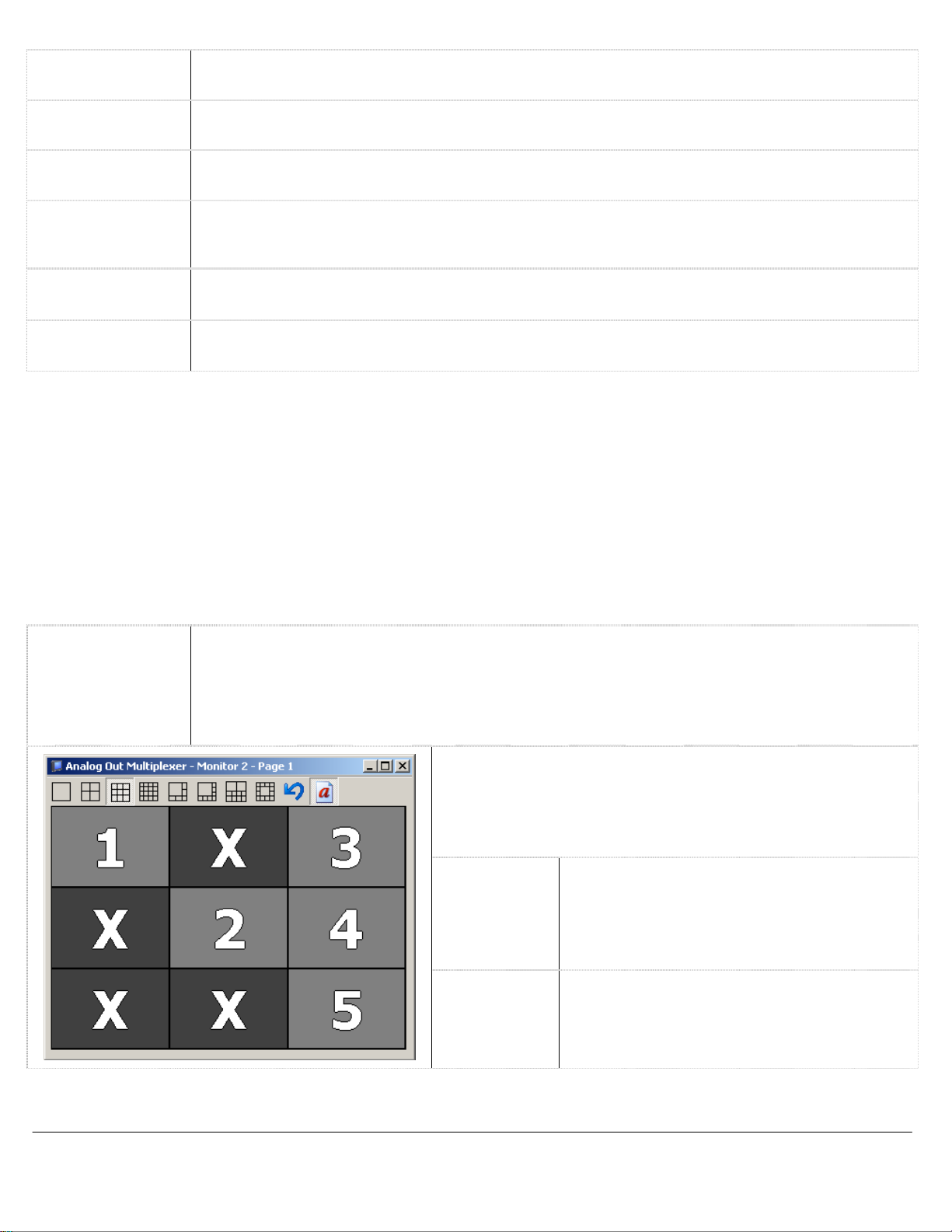
Analog Out Multiplexer window (see below).
use
with this capture card type,
the camera displayed
click on
you can also select
To
arrange cameras within the selected
a
particular position
configured separately
the desired monitor number before selecting th
on
and select a
for
each
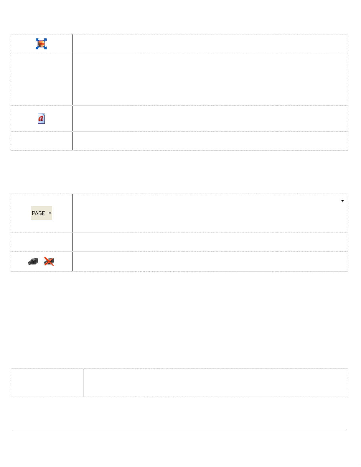
Undoes any
made since
window
Toggles captions on and
Output Monitor
option
or off, corresponding to
video
to
analog
the monitor
the Setup Analog Out Multiplexer me
grid
layout
the
was last opened.
video feeds.
Zoom in and
is
available
in
the camera settings.
feed
was on
another camer
and
then use
enabled by
closed an
monitors. Outputs with
Live
Viewer.
the
DVR model specificatio
and one monito
by
display grid, right-click on
camera. Camera positions ar
style.
changes
Analog
The
number of
r
all
with multiple
selecting the camer
that
have bee
Output Multiplexer
off for the Analog
d
a
n
x
a
e
nu
e
n
Page
ETV System
Server Software - User’s Guide
13
Page 14
3.4
Live Viewer Display Control
Changes
right corner or press the
Click
the layout wher e the
Note:
menu, or
camera positions
and click Reset To Default.
Toggles
Note: Captions
Toggles
When in
the right-click context
The
Hardware Rendered mode,
following buttons are available
Cycles
allows you
Note:
function
Certain capture cards
entering the settings,
one of these
3.5
Depending
outputs.
Alarm inputs
can be
two modes.
Alarms and
on
The
number
can
triggered
Toggles captions on/off
Turns on/off
you can click
the hardware installed with your
of
trigger recording
by
motion alarms,
s
,
click
the
X in
the
Live
Viewer to full
escape key on
the Restore Original Display Layout button to return to the previously displayed layout or to
last
camera
To
reload default window
select Reset
captions
the display
Window Positions
to default for the current layout, right-click
on
the
Live
are not included
size
of the camera
some of
menu only has
through
to select a
When in Single Live View
is
to
all live video
the options
in
the
Live
which
camera
camera directly.
change between cameras rather than
the
feeds.
can change between Hardware Rendered
the arrow
Relays
available alarms
Opens
the
Live
and
of video and/or
video
loss,
Alarms or
screen
change was made.
sizes and locatio
Viewer
in
mode.
the keyboard.
from the
video
the recorded footage
when in Single Live View
feeds
To
exit full
ns,
select Tools | R
Tools
on and off
screen mo
button drop-down menu.
on any
.
.
d
eset
Window Positions
camera feed within that layout
display mode
.
the options differ from Software Rendered mode.
of
Copy,
Viewer window f or Hardware Rendered mode
is
displayed
display mode, the button
Live
Viewer
This
beside
Full
video feeds.
feature
the
Live
Screen
in
the first position
does
and Quick Search.
pages
not affect recording.
and
button
on
:
in
the
live
viewer window. Clicking
PAGE is
of cameras.
replaced with CAM, where th
Software Rendered mode. Instead of
the
main VIGIL
Server toolbar to select
DVR
unit,
relays
is dependent on
audio based on an
POS
data, or failure
Relays window.
you may have access
your hardware.
externally tripped circuit.
of
the DVR.
to alarm inputs or relay
To reset all
the bottom
from th
For example
Relay output
e
,
e
s
Page
ETV System
Server Software - User’s Guide
14
Page 15

3.6
The Media
are configured
The Live
Green: Alarm input
Red: Alarm input
The Relays
Green:
Red:
You can
In
and cannot
Alarms window indicates configured alarm inputs.
is enabled.
is triggered
window indicates configured relay outputs
Relay
output
Relay
output
manually turn on/off some
the example image, the 6
be
turned off manually.
is enabled.
has been
.
triggered
Media Drive Information
Drive Information section is a live view of
on
the DVR.
The
status of the data drive
Configured driv
Currently recording
Drive warning
Drive er r or , c ontact yo ur syste m administrator.
The percentage
Further drive information
drive
and
the available/total
To view
drive information for your
e
of free
is indicated
on
this driv
space is listed
is accessed by
space
relays
th
relay
has been set
the status
by
e
following the
of the drive
audio
devices,
and allows
by VIGIL Server.
by
clicking
of
its icon
clicking the + next to the drive. Here, the path of th
is displayed.
click
on
their respective button.
to
stay closed while
the
video and audio
:
name
of a drive.
the
Audio tab.
manual control of relays.
the application
data storage
is open
drives that
e
Page
ETV System
Server Software - User’s Guide
15
Page 16

3.7
Pan/Tilt/Zoom (PTZ) cameras
Live
Viewer wi nd ow . T h er e are three major
cameras, IP
Digital
PTZ
PTZ
Camera Controls
PTZ
cameras
camera control
allow
and
hard-wired
allows
navigation to
users to
controlling the physical camera i tself. Digital
live
viewer that are not assigned to
right-click the camera
single-vie w , m ul t i- v ie w
IP PTZ
network connection
Hard-wired
cameras must
PTZ
cameras are
through a camera input
in
the
and
full-screen mode.
be
set
to the DVR.
on
the DVR.
live
up
any
viewer,
individually
also set up
an
area
types
of Pan/Tilt/Zoom (PTZ)
PTZ cameras.
zoom in on a fixed
PTZ
camera control
other type
and
then select Digital PTZ.
in
the
of
DVR
individually
Dropdown
Selection Box
Pan-Tilt
Zoom/Focus
Iris
/
of
interest
and
are controll ed
cameras t hat exist: digital
camera
is
automatically enabled for
camera control.
settings
in
the
This is a menu
DVR.
Shows/hides additional
Use
the
the
blue
Pan-Tilt control
direction.
camera
is
dragged closer to the
circle.
and
DVR
Select a
mouse
dot
The speed
moves
and move
To disable
The live
digital
control the physical camera through a
settings
of
camera to
in
increases
and
control the physical camera
all
the
PTZ
cameras configured
load
for control.
PTZ
camera control
to click-and-drag
the m iddle of th
in
the desired
at
which th
as
the dot
edge
of th
The
alternate directional control
are displayed
PTZ
camera
range of motion (i.e. it cannot pa
and
tilt at the
the Push-Button Controls option is
enabled.
when
does
same
the selected
not support a full
time), or whe
Click-and-drag the appropriat e
down
to decrease.
adjusted increases
ce
nter
of the control.
The speed
as
the bar
at
is
by
the user from th
PTZ
within the
image withou
all
cameras
in th
or re-enable the control,
PTZ
control works in
on the
s.
e
e
e
s
n
n
slide
bar
up
to increase or
which
the camera is
moved farther from th
e
e
t
e
Page
ETV System
Server Software - User’s Guide
16
Page 17

Joystick
This
window
buttons.
button.
allows
Use
the drop-down
for customization
menus
To
determine
Panel and select Game Controllers,
Select
the button numbe r
it
which
button
and click Properties. Click any
will be
is
which,
highlighted
Presets
To save a
the drop-down
number.
To move
Goto, or
preset,
the camera to
click
move
menu a nd click
an
the button with the pr
the camera to the desired pr
existing preset,
Patterns
Select a
move the camera
saved
pattern.
pattern from the drop-down
pattern.
in
the desired pattern.
Select a
pattern from the drop-down
If
a USB PTZ Jo
it
opens
the Jo
of
each
of the jo
to
assign
go
where the
in
Presets are fixed locations that the camera
within the camera for hard-wired
cameras.
Save.
eset
Control the
within the camera.
menu and click
actions to ea
into the Windows Contro
device will be listed.
button
on
the resulting window.
This will
select a pr
number
saved
Once
finished,
ystick
the jo
eset
overwrite
eset
on it
.
pattern of movement for the selected camera. Patterns
Record.
menu and click Run
ystick
is
attached, this button
ystick Customization window.
ch
l
ystick and
PTZ
cameras,
location,
any pr
from the drop-down
Use
click
Stop.
select
esets previously
the other control buttons to
This will
to
will be
can save and go
and in VIGIL
the pr
eset
number from
saved
menu and click
overwrite the existin
begin
the saved
to that
available.
to.
The pr
Server for digital PT
g
Once clicked,
esets are store
are store
d
Z
d
Page
ETV System
Server Software - User’s Guide
17
Page 18

Tours
Click
Settings to
specified number of
Click Run
window.
to activate the tour.
The
tour
Note: Presets must
Enhancements
Enhancements can be
Menu
A
open
the Tour Settings window, where pr
seconds
can be ended by
be
Some
before
configured before a tour
selected
tour
is a cycle
going
to the next pr
The
via
camera
moving the camera or pressing Stop.
Settings
Backlight, White Balance and Auto F
the Drop
will cycle
can be run
Add
Edit
Delete
Save
Cancel Exits the Tour Settings window without saving
on
the camera that
Down Box and
cameras
have
Displays the camera’s menu; it
Exits the camera’s menu.
click
the
Camera
of camera presets. Tour settings are stored within VIGIL Server
esets are
eset.
through the pr
.
Adds a pr
Edits
a pr
Deletes a pr
Saves changes made
turned
built-in
Select button.
menu
menus
navigation butto
added and set to run for a
esets
in
the
Live Viewer
eset
to the tour
eset in
can be toggled on/off. These
on
the tour.
eset
from the tour.
ocus.
or off
via
that
can be accessed and
may
You can also
ns.
.
to pr
esets.
the butto
take a moment to appear.
navigate to the Exit
ns.
any changes.
include Color, Sensitivity
configured
via
menu
this tool.
option an
.
,
d
Camera
ETV System
Server Software - User’s Guide
menu select button.
Page
18
Page 19

3.8 Live
Live POS/ATM
Access
Live POS/ATM Data from the
Data
Control,
(Live) window displays
POS / ATM Data
data refers data generated
and
received
by VIGIL
Tools
live
data from
by a
compatible data system
Server
button drop-down
in
real-time.
all
configured Data Sources.
To open
menu in
such as a Point of Sale
the POS/ATM Data (Live) window, select
the
main VIGIL
Server window.
system,
The POS/ATM
ATM or
The POS/ATM Data (Live) window presents Data in
• Qty. – The
• Item – The
• Amount
• Code
•
Reg # – The cash
• Cashier
• Receipt #
• Timestamp
• Idx
– A
quantity
item purchased.
– The
– The
transaction
– The
– The
– Th e
unique identifier to quickly identify
of
the item purchased.
price
of
the item purchased.
code
identifies the type
register number.
cashier currently
receipt number
time at
which
logged
of
the current receipt.
the Point of Sal e
The
column headers are
click on
positions.
Column Order.
the column header that
To
reset the colum n locations, ri ght-cli ck
Double click a
all able
to
be
resized
you would like
column header to automatically resize the column to the content width.
Note:
columns are designed for
matching column.
Some
types
of Data sources
POS
Data, other Data sources are d esigned to insert Data to the closes
do
tabular form with these columns:
of transaction.
into the data terminal.
event occurred.
and find Data
as well as
to
move and
not support
rearranged within the window.
then
in
the POS/ATM Data (Live) wind ow
all of
line items.
click
another column header to
the columns that are avail able. Th
To move a column
swap column
and select Reset
e
,
t
Page
ETV System
Server Software - User’s Guide
19
Page 20

There are
Copy
Data Filter
Export
Reset Column
Order
Print
five
options avail able
Line
Copies
Prints
R
esets the order of the POS/ATM data columns if they
when
the selected data record to the Windows clipboard.
the POS/ATM Data (Live) window
Filters
number. Enter
and click
Note: Filter clears the window
effect
after the filter
Opens
export destination
selection, the
opens. Select
select Export
Once
process.
the
live POS/ATM Data to the default printer.
is right-clicked:
the
live POS/ATM data
the register number
OK.
Click Cancel
on POS/ATM data that
has been applied.
the
Select Destination
is
selected. After making a
POS/A
TM Export Settings windo
the time periods to export or
All
to export
complete,
Click Cancel
have been rearranged.
click OK
to exit without saving.
by register
in
the bo
to exit without saving.
and take
is capture
window where an
all POS
to
begin
s
d
data record
the export
x
w
s.
Page
ETV System
Server Software - User’s Guide
20
Page 21

4 Searching
VIGIL Server offers a robust set
window, either
from the
main menu.
The
Search window
section
on
Each of
a section
the Search window sections
is
click
Search
is
divided into two major portions:
the right.
already minimized, it
on
of
tools for sea rching
the
main VIGIL
can be
can be
restored
Server
minimized
using
and
playing
icon
toolbar, or select Search | Search Footage
the playback section on
by
clicking the
the
video footage
double
double arrows.
and
data.
the left
arrows
in
To open
the Search
and Data
and
the searchin
the title bar.
g
When
Search
Reset
POS/ATM Data
Performs
R
esets
past
If
Search Results sections.
search criteria.
ETV System
a
search
all
search criteria
hour from
a POS data connection
based on
when Reset is clicked.
the current criteria.
and Data filters to their default values.
has been
Click
the POS/ATM Data Filter section
Server Software - User’s Guide
configured, this button
The From/To
will open
title bar
time defaults to th
the
POS Data Filter
Page
e
and Data
to specify the Data
21
Page 22

4.1
When
hour.
Searching Video
first opened, the Search window defaults to a search
Click
the Search button to retrieve
all
footage meetin g the spe cifi ed criteria.
of all
cameras, recording
in all
modes, from the last
You can
allows you
Settings window,
specify the start date/time and e nd date/time
to search
in
the
across
DVR
multiple days.
Settings | Search Tab.
This can be
of your search.
changed to default to
By
default, VIGIL Server
One Day in th
e
Note: If
following prompt
the searched footage
will appear:
To date or time
is
older than the
oldest footage
on
the DVR, th
e
To
From/To
automatically adjust
Yes.
If
you do
not want to
Note: If
following prompt
To
click
Presets
Mode
Cameras
This
hours. Additionally, selections
Short Intervals in
times are adjusted
searches
Making a
type:
Alarms or
This allows you
se
arched.
the searche d footage From date or time
will appear:
automatically adjust
Yes.
If
you do
drop-down
that are performed frequently
selection from this drop-down
All
menu
Modes, Constant,
Video Analytics Alarms.
to restrict your search to a limited set of cameras.
the
To date to
have
the date range adjusted, click No.
the
From date to
not want to
includes pr
the Settings | DVR
accordingly. Selecting Custom Search
have
for
Motion,
be an
the date range adjusted,
eset
search intervals
15 and 30
Settings | Search Tab.
can be created or run.
All
hour later than the oldest footage on
is
newer than the newe st footage
be an
menu will
Alarms, Digital Input
hour earlier than the newest footage
minutes
restrict the returned footage to
click No
in
hourly increments from
can b e added b y
When a
opens
.
checking
selection
the Custom Search window wher
Alarms, Motion
By
default,
the
DVR click
on
the DVR, th
on
the DVR
1
hour
up
Quick Retrieve
is
made, the From/T
only
the selected
Alarms, POS/ATM
all
cameras
will be
e
to 8
o
e
Page
ETV System
Server Software - User’s Guide
22
Page 23
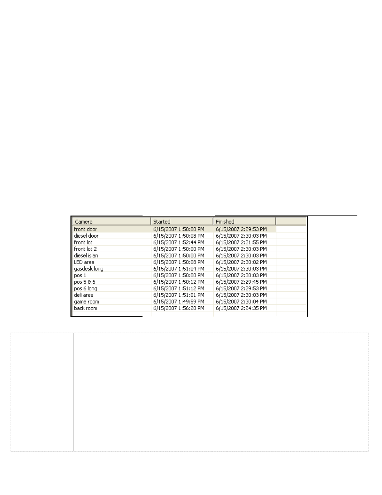
Video Search Results
After completing a search, the resul ts are displayed
is
expandable
and
collapsible
if
the POS/ATM Data search
in
the
Video
Search Results pane as seen
is enabled.
below.
This pane
Visual / Tabular
Visual Display
Tabular Displa
Click
this button or
Visual
period of time searched with footage recorded displayed
mode: Green for Constant,
When
cursor,
playback of the selected camera at that time, clicking
playback of the next available
Tabular
Clicking
gaps in video footage.
display
the
mouse is
which is
display
on a
use
the drop-down
is a
graphical representation of the search results.
Blue for Motion
moved within the chart,
displayed
is a
table row
below
footage.
table with the start
will begin
menu
the
Video
and end dates and
playback of the selected camera.
y
to switch between
or
Red
a line is
Search Results.
Visual and
The visual footage chart
as blocks
for Alarm.
drawn indicating the point
Clicking within the chart
in a
white sectio n of the chart
times of the available
of color representing the recordin
The
Tabular display options.
shows th
in
time under th
will begi
will begi
video footage
tabular display cannot show
e
n
n
.
e
g
Page
ETV System
Server Software - User’s Guide
23
Page 24

Zoom In
Allows you
Zoom Out Allows you
Single / Multi
Screen
The
Screen will
four cameras simultaneously
the
Playback
4.2 Searching
to
zoom in on
to
zoom
playback options allow you
display
window
the
Visual
out
on
the
one
camera at a time during playback. Selecting Multi-Screen
in a 2 x 2
by
selecting them
POS/ATM Data
display
Visual
display
to control
Video
Search Results for greater precision.
Video
Search Results for a wider view
how
your results
multi-screen layout.
in
the results panel.
will be
played back. Selecting Single
In
either mode, cameras are
.
will play back up to
added to
Configure
POS/A
POS/A
a POS/ATM
TM Data Filter
TM
filter criteria section.
and Data Search Results sections. Click
data connection in
Search for Line Items
the Search for
Use
Criteria section.
date/times, selected cameras).
Item
Code
Type in
Register Type in a
Quantity
Type in a
Value
C
ashier
Or/And
Type in
Line Items section
When
searching for
Type in
remembers last
Matches
certain value,
value
that
data
with the
equal
to”,
Logical
operator,
operator
to
line
text to search
10
searched
text to search
number to search
number to search
results
text to search
operators that
which wil l
will
in
the Amount column.
select an
you
input.
value
of 20.15
while
the = operator simply
match results
match results
the Data tab
and click
the POS/ATM Data button to
the POS/ATM Data Filter title bar to
find spe c ifi c Data within the date
items, norm al s ear c h c ri t eri a are
by
Item.
by Code.
by
by Quantity.
operator
For example,
by
cashier number or name
will assist in
in
Use
the drop-down
for items.
Register Number.
and
all of t he
By
and
input
if the operator >=
higher
means an exact value.
searching with multiple criteria.
in
any of the
used POS data criteria fields.
menu
default,
a
will be
Any
value.
The
is used
returned.
.
used POS data criteria fields. Alternatively, the AND
Price
>=
The
and
time indicated
also
included (i.e. From
to
select a
is
selected.
means
with the
“more than or
<= operator
open th
open th
in
the Search
recently searched item
If
you
want to match a
equal
value
of $20.15,
means
By
default, this
any POS
“less than or
is
and T
to” th
the
e
e
o
,
e
OR
Page
ETV System
Server Software - User’s Guide
24
Page 25

Search for Transaction
type
of
This
search
looks
Receipt Number
IDX
Note: Depending
matching your search criteria.
Type in
before the start of the receipt
Type in
returned
is no
timestamp of that IDX.
The
following opti ons are available
clicked:
Copy
Line
Copies
Export
Saves
file name, then
Print
Mark Video Region
Search for Receip
#
Reset Column
Order
Note:
footage that matches that selection, the next available
POS/A
When a POS/ATM line
TM line
Prints
select Print Data from the context menu.
Adds
10, 20, or
this option to
t
Narrows the Data Search Results to display
R
item that
for a unique
text that
text that
will be
receipt number for the searched IDX
on
the recording configuration
the selected
the selected POS/ATM data to a preset
the selected POS/ATM data to the default printer.
markers to the playback
30
esets the order of the Data Search Results columns to their default positions.
is associated
line
item or receipt number
will
match results
and 10 seconds
will
match results
that receipt number
The
search results
when a POS/ATM
line
of POS/ATM data to the Windows clipboard.
click
Save. Export destinations are set
seconds.
become available.
item
You
must
is selected
with it.
and
disregards the other criteria.
in Receipt
in IDX
and all IDX values
# column.
after the
column. If the IDX contains a
value, the returned results
will be
of
+/-
your cameras, there
The
search results
end
of the receipt.
corresponding to it within
10 seconds
from the timest amp of the IDX.
receipt numb er, the Data
may be no footage
data record within the Data Search Results pane is right-
destination. Select the destinatio n folder
in
slide
the Settings under
You can also select
bar to
have
in
easily
identify relevant portions of video. Options are +/-
the
Playback
only
window
items with the sel ecte d Receipt Number
the Data Search Results and
video
frame
will be
open
with
displayed
Media Drives.
video footage selected fo
there
will
include
will b e based on th
the printer button an
is no vide
along
10
one
hour. If there
and
.
with th
second
enter a
o
e
s
e
d
r
Page
ETV System
Server Software - User’s Guide
25
Page 26

4.3 Custom Search
A Custom Search that includes specified search criteria
can be a cc ess ed
menu
(Search | Custom
from the Presets | Custom
Search).
When selected,
Search drop-down menu.
the Custom Search window
Description
Server
Time Filter
The name
appear
Select
will be
list.
The
arched.
se
Cameras
Data
Select
select All Cameras.
Include Data
Custom Search
POS/A
OR/AND assist in
criteria.
operator,
any
fields.
match results that
results
criteria fields.
Click OK
run. To do this press the OK or Apply buttons.
to return to the
of the search that will
in
the Custom Search list.
the server the custom search
run
on
from the drop do
start time
the camera(s) to search, or
TM data criteria specified.
of the POS/ATM data criteri
The AND
in all
and end
– When
will
Logical operators
searching with multiple
By
default, this
which will
operator
of the POS/ATM data
time to be
enabled, th
include th
match results in
have matched
e
that will
is
the
will only
main Custom Search window.
wn
e
OR
a
can be created and
Delete
saved.
It
can also be opened
The Custom Search window
will appear.
Add
Edit
Run
Opens
window.
been
se
Opens
window for the selected search
Select an
a
click Apply
the
Once a
added,
arch.
the Edit Custom Sear
Custom Search
Deletes an
Select an
Runs an
Select an
from the toolbar
Add
Custom Sear
Custom Search ha
click Apply
entry
and click Edit. Once
has been edited
to
save
the changes.
existing Custom Search.
entry
and click Delete.
existing Custom Search.
entry
and click Run.
to
save th
ch
ch
.
Note: You must save C ustom Searches before the y can be
s
e
,
Page
ETV System
Server Software - User’s Guide
26
Page 27

4.4
To play
camera
Note: Network camera s
Recording
Video Playback
recorded
will load
video
for playback
Speed
footage,
window, depending
click a
and
the retrieved footage
may
record
camera
and play back
on
in
the
Video
will begin playing.
at a slower rate than what
the available bandwidth.
Search Results pane in
the Search window. The
was
set
in the
Information about the camera
playback status, the date
recording
CODEC of
the footage, the current frame number,
and
ETV System
Server Software - User’s Guide
feed is
time
of
displayed
the footage, the frame rate
below
the
and
Playback
the total number
window.
if
currently playing, the resolution an
This
information includes th
of frames.
Page
27
e
d
Page 28
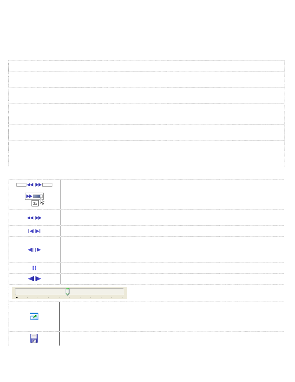
Controlling Playback Video
Cameras
Viewer.
video.
control type sp ecifi ed
screen,
can be
Because
The
digital
and
controlled during playback
digital
full-screen mode.
PTZ
PTZ
controls
in
Camera Right-click Menu:
Remove
Removes a
Copy
Copies a still
Zoomed option
For cameras
following right-click
Source Video Only
(Rotate Disabled)
Source Video Only
(Rotate enabled
360 View and
Source Video
Playback Buttons
using
the
Panorama
menu options:
This
)
:
option
playback.
move
This
feature
interest
feature splits the playback
This
and
the second, third
area of interest
quadrant to
Click-and-drag the Variable
variable
than the
Click
any frames.
Skips
Skips one
While paused
used
Pauses
Plays
Stretches
Note: Footage
window.
For Exporting
with Digital PTZ:
using
the digital
PTZ
controls movement within the image, it
will
work for ev ery camera that
the settings.
camera from playback.
shot of the current
PTZ
camera control type, the
is
enabled
Click on an
the
image
allows
and
then
load
speed
Recorded Speed.
the
Fast
Backward or
to the very beginning/end of the
th
10
of the footage if
or stopped,
to
do
this
the
video footage
the
video footage backward or forward.
the playback
Still Image,
The
digital
will be
recorded
available
by
default.
area of interest
after it
in one
that section.
playback tool tip displays the number of times faster t he variable
by
is
zoomed in.
users to
use
the
mouse scroll
and
fourth quadrants show
of the
Speed Playback
You can also
Fast
click
selecting the playback slide-bar.
.
image
in
704x480 resolution or higher
Video Footage, Audio
PTZ
control works
image
as well.
zoom in and
zoom
The
clicked while
to
Click-and-drag the slide-bar to
video clip.
to fill t he
to the Windows clipboard.
video can be
This
feature
and
then
rotate cameras during playback.
to
zoom
image
Forward
into
4
quadrants,
zoomed sections
Slider to
right
click on
button to
video footage
playing the
play back
frame
Playback window.
camera control
can be used
is loaded
allows
use
in. Or, click-and-drag to rotate the image.
quadrants.
different zoomed sections of the image.
click on a zoom
can be clicked on
or
POS Data.
for playback regardless
in
single-screen, multi-screen, zoom-
manipulated
users to
the
mouse scroll
The
change
the button to select
play back
.
video footage.
by
frame.
is scaled down
in
the
same way as
for both
live and playback
of
If the
image is
in
the playback window
zoom in and move
to
zoom
first quadrant
quadrant
the
speed
at Maximum
The mouse scroll wheel can also be
move
and
directly
of the
the
to
to fit within the Playback
zoomed in, a Cop
cameras during
in. Click-and-drag to
Click on an
shows
then
and
speed directly.
speed
a
different point
the full image,
click on
then rotated.
video
playb ack. The
speed
without skipping
the Live
the camera
y
using th
area of
To load
playback is
an
the first
in th
e
e
Page
ETV System
Server Software - User’s Guide
28
Page 29

Cue Frame
Zoom / Normal
Screen
Click and select Print
data
currently displayed
Search Results available.
Click
to authenticate the currently selected
Click
to toggle the Data On-Screen Display feature, where POS/ATM data
video footage.
Click
to
play in Full Screen
window.
Note:
zoom
Cues
Frame button.
Enlarges
Screen
To zoo m in on an image in Full Screen
out
on an
the playback
the
Playback
mode,
click
Still Image
image,
video
the Normal
to print the current frame, or select Print Data to print the
in
the Data Search Results pane. Defaults
video
mode. Double-click
hold down
to a specific frame. Enter a
window
the Control key and right-click.
so details
Screen
in
the playback
button to return to the original window
footage.
on
mode,
For
the
image
hold down
frame number
image
to Print
more information
to return to the standard Playba
the Control key and
in
the text
are easier to see.
Still Image
on authentication.
is
displayed with th
left-click. T
box and click
When in Zoom
.
if
POS
no Data
ck
the Cu
e
o
e
Displays the Camera
name
currently playing
and
the type of recording.
Page
ETV System
Server Software - User’s Guide
29
Page 30

4.5
Select Multi-Screen to playback
quadrants;
on
its
name
replace
one of
Multi-Screen Playback
they are
or
the initial cameras. Footage
some
filled i n
point w it h in its timeli n e. If
up
to four cameras simultaneously.
clockwise order beginning from the top left.
all
quadrants
will play back
from
have
all loaded
The Playback
cameras loaded, cli cking
window
To add a
cameras simultaneously.
camera to the playback, click
will be
a new
divided into
camera will
Note: If a camera
video will pause
play.
When
playback
time where footage exists for at least one camera.
the playback time reaches a point where the
will
resume.
Note:
button
To
in
the
revert to
Video
does
not
with
an
overlay stating “No frames were found”
When
Single
Search Results section.
Screen playback, first select
4.6 Advanced Features
Smart Search
Smart Search feature refines the
The
region.
To
perform a Smart Search,
Mask and
Alternatively,
perform the search.
will be loaded
draw
on
when a
for playback.
Once
the pl ayba ck image.
masked area
you
must first
the search
have
footage for a time
there
is no footage for
loaded video
is clicked
is
complete,
define
Any
on, the
when
any
a
footage
or “mask” a motion detection region.
time
a
clear area
mask is
only vid eo
other cameras
while
paused
camera, the playback
camera
based on
removed.
frames that contain motion
camera
and
then
motion detected within a user-define
is clicked
Click
do have
other cameras continue to
has
click
on, the
the Smart Search button to
footage, th
more footage, it
skips
the Multi-Screen
to the next
To do
this,
click Show
mask is expanded
in
the masked region
e
s
d
.
ETV System
Server Software - User’s Guide Page
30
Page 31

Note: If there
Search
will load video
is
more than
one
masked region (i.e. two or more disconnected masks), the Smart
frames that contain motion
in any of
the regions.
Show Mask
Sensitivity
Smart Search
Visual Track
Analytics
Shows/hides the smart search mask.
latched on.
Offers
some quick options
C
lear
–
Mask
Reset
Removes all
Select
Invert - Swaps
Note:
The Show Mask
This
slider controls
function.
sensitive, detecting smaller movement
Performs the Smart Search.
removed from t he
Search frame.
Displays
Erases
All
– Masks
To
the left
Smart Search
a menu
A mask can only be
for modifyi ng masks:
all masks on
the entire image.
clear
and
the sensitivity of the motion detection algorith
is less
loaded
where
the image.
masked area
button must
sensitive, requiring larger
Video
footage.
masks and
Video Analytics information
s.
be latched
.
frames that
Use
the buttons to
restores the originally
When
objects
on
for th
ese options to
change in motion;
do
not contain motion
enabled, the
by
the placement of white corner s around the object.
Visual
can be
edited
loaded footage
overlaid
when
the
Show Mask
be available
used by
m
in
skip back/forward
.
Tracking feature tracks moving
on
the playback footage.
.
the Smart Sear
to the right
the masked regions ar
to the next Smar
button is
ch
is a more
e
t
ETV System
Server Software - User’s Guide Page
31
Page 32

Zoom
Playback
cursor
footage
is
moved over the
can b e
magnified. Left-clicking
are
also
available
in
The
magnification factor
zoomed
Playback
zooms in and
the
Zoom tab.
is
displayed
by selecting
window,
right-clicking
the
a zoom
Zoom
outline
zooms
in
the upper right-hand corner
tab from the Advanced Features section.
will be
out
displayed to indicate the region that
of
the image.
Zoom
In
and Z oom Out button
of
the
Playback window.
When th
will be
e
s
Adjust Image
When
Features
playback
section.
Brightness
Contrast
Grayscale
Reset
Note:
intensive.
is
paused,
The adjusted
Toggles
Adjusts
Adjusts
Returns the
you can adjust the
image can be
the brightness
the contrast of the current frame.
between a
image
of the current frame
grayscale
to its default values.
image by selecting
exported or printed.
and
color image.
.
Only still images will
Only a paused image can be adjusted; adjustment
Any adjustment
you have made will be
reapplied
the Adjust Image tab from the Advanced
export
of
footage during playback
when footage
is paused again.
in gray
scale.
is
too
CPU
ETV System
Server Software - User’s Guide Page
32
Page 33

Markers
During playback,
Markers.
To use
if only a
sub-range
of
the
loaded
footage
is of
interest it
can
quickly
Markers, select the Markers tab from the Advan ced Features section
.
be selected
by using
Start / End Range
P
osition the footage navigation slider at the beginning of the sub-range
button.
the sub-range
Clear
Removes
the playback
View
Note: If
own
multiple cameras are
unique sub-range
Note: If a sub-range
Audio Playback
If
audio
Advanced Features section
playback recorded
recording
Loads
currently displayed.
is
enabled
audio along
You will notice a small
and click
the sub-range markers.
will
return from the sub-range to the fully
the sub-range for playback.
the
All
of the playback controls will operate on only
loaded
marker appear
End Range button.
If
the sub-range
The
for playback
playback information
in Multi-Screen mode,
of footage.
has been
and
of
defined,
configured
only
the sub-range
in
the
DVR
settings, the
the Search window. Selecting an audio
with
video footage.
and click
below
the starting point. Next, navigate to the
is
cleared
loaded footage.
when
the
View
button
will indicate
the sub-range of footage.
each
camera
that
can have it
will be saved when video is exported.
Audio
tab
will become
available
channel from this tab
the Start Range
end of
is latched on,
a
sub-range is
s
in th
e
allows y ou to
All Audio
Video Only Audio
To choose which audio
Audio tab.
When
corresponding
When
video footage for the playback time.
This Audio Level Meter indicates
ETV System
channel to playback,
selected,
selected,
all audio
video footage for the playback time.
audio
from the specified channel
from the specified channel
the
signal
Server Software - User’s Guide Page
select
strength of the currently playing audio.
the channel from the drop-down
is
is
played
played
back only when
back even when
there
menu in the
is corre
33
there
spondin
is no
g
Page 34

4.7
Frame
recording at resolution
De-interlacing
Frame De-Interlacing
applies only
704x480.
When p aused in
Full
the drop-down arrow
4.8
VIGIL Server embeds
checked
If the
video has been
halt at the first damaged frame
message
Authenticating
a
to verify that the footage
Begins
length
can cancel
to cance lli ng
message
tampered with, the authentication will
with the problem frame number.
to
DVR480
the
Field,
AF – A Fi eld and BF – B
Series
Playback
menu
to
Recorded Video
security
the authentication process;
and location
and
key in
is
the authentication at
have been
will be displayed.
provide
recorded footage for
authentic
of the
video
authenticated. If the
an error
DVRs
window,
Field.
select
and has
footage, Authentication
any
running VIGIL
use
the
Click on
the frame type.
not
been
a
window
time
by
If
Real-Time Authentication (in
is
enabled, during playback a large red
the frame if the footage
Server version 2.03.00 00
Frame
each video
De-interlaci ng feature to to ggle between
the F button to toggle between frame types or use
frame.
These keys can be easil
and higher
tampered with.
opens
clicking Cancel.
displaying the progress. Depending
may
take several minutes to complete. Yo
Any
frames that were processed prio
video is
authentic, the Authentication Complete
DVR
Settings | Search tab)
X is
does
not
pass authentication.
displayed over
F
on th
,
-
y
e
u
r
ETV System
Server Software - User’s Guide Page
34
Page 35

4.9 On-Scr een Display -
When POS/ATM
feature
ack.
b
can b e
search results are
found and a
enabled. Enabling this feature
POS/ATM Data
camera
will
is loaded
overlay POS/ATM
for playback, the On-Screen Display (OSD
records
on
the
video whil e
it
is played
)
Enables/Disables the
to Enable/Disable
Note:
The OSD
latched on.
OSD
the
feature
OSD
is
of
POS
or
open
available
data.
The opens
the Configure
when
the
POS Data button
the
OSD
OSD window.
context menu, allowing yo
in
the Search window is
u
ETV System
Server Software - User’s Guide Page
35
Page 36

Dwell Time
The
Number of Lines The
Backgroun
Transparent/Color
d
Change
Font Color/Size/Bold Change
Horizontal/Vertical
Offset
The
Col
umn Selection
OK
Specify
When you
return to the Search window.
OK
.
button to
number of
maximum numb er of r eco rds to display at a time.
the text backgrou nd color/transparency.
the font color/size/boldness.
number of characters to offset the text from the left/top side
whic h
seconds a data record
columns to
are finished confi guring the OSD,
display on-screen. Unchecked columns
will
remain on-screen
click
the
.
will
not
be displayed.
apply
your
changes an
d
ETV System
Server Software - User’s Guide Page
36
Page 37

5 Exporting
Video
be saved
“exporting”.
5.1
Single
all of
compressed
footage
can be saved
either embedded within
Note:
Note: If
To
export
Export Auditing
destination folder for both
Exporting, Printing,
frame shots can be saved
the original
and
are typically indistinguishable from the original
Still Image
E-mail
either
you
must
have
is
images and video exports.
image
detail, but are typically
Opens
when Video Footage
Select
enter a filename.
the Export context
Bitmap to
Select JPEG
a
filename. Additionally,
Closer to the left
quality, larger
Save when
Select
body and recipients.
to
finished or
Bitmap or
Note: For
tab.
Prints
Note:
an
error message
email
to the Windows default printer.
The image will be sent to the default Windows printer only.
as a single
video
at least one
frame still shot or
footage or
in a separate document.
export desti nation configured.
as a video
enabled, required information must
or Emailing Images
or emailed
is
save
Click Save when
save
the current frame
side means a
sized
file. For
JPEG
to function properly,
will
in
either Bitmap (BMP)
much
menu
where the file format
selected
the current frame
Cancel
to
inform
in
the
Playback window.
finished o r
you may sel ect a
lower quality, smaller
the
most
to exit without saving.
E-mail
the current frame
a valid SMTP
Select
multiple destinations
create
Exporting
you
the destination
subdirectories
Click
of this.
larger than
image when
is selected. The Export button
in
bitmap .BMP format.
Cancel
in JPEG .JPG
quality setting for the
part, the default compression setting
a
Bitmap the Quality slider
this button
to exit without saving.
format.
in .BMP or .JPG
Server must
you
by
by using
file,
audio and POS/ATM
This
process
be
entered before selecting th
or
JPEG (JPG)
JPG images as a
the
Select
sized file; further to the right
want to
checking the corresponding
and select Print
format.
result.
JPG
quality
Select
JPG image by adjusting the slider.
be
save
the
the export destinations an
the export destination
format. Enter
configured
the
New
will
not
be visible.
Still Image.
If
one has
is
BMP images retain
is 70
is
the
the
in
the
image
to.
Folder
not
data ca
n
referred to as
e
JPG i mages ar
or greater.
is only enable
and ente
means a higher
best
choice. Cli
email subject,
DVR Settings
You can select
boxes, as well as
button. When
been configure
e
d
d
ck
d
r
ETV System
Server Software - User’s Guide Page
37
Page 38

5.2
Video
M
Player
footage
otion
JPEG AZTECH
program. AVI format
Exporting Video
supports standard
evidence
since
to include the
Video exports.
AVI
Authentic Video
Data
can be
exported
format.
AVI
format.
the authenticity
VIGIL
DV
player installation kit
Opens
Saves
Clicking the Advanced button
image size
and
Click OK when
Saves
filename.
Export
the Export context menu.
the current
configure the
the current
the POS/ATM data
Note:
To
Data tab.
in Microsoft AVI Video
Video clips
exported
video clips can be played using
The
Authentic
of
the
clip can be
video footage
the
video will be saved
CODEC use d
finishe d or
video footage
Click Save when
export
POS data
Video
verified
file
to ensure that playback software
Select
in AVI format.
will open
at.
during the encoding proce
Cancel
in a
to exit without saving.
in MJPG
finished, or
text file.
you
must
format or
in
Authentic
format
using DV Player. VIGIL
the type of file
the
The … button
Cancel
have
the
in
Authentic
Video
Windows
is
recommended
Select
CODEC
format.
to exit without saving.
POS
Terminal Settings configured
format
Media Player or any other player that
you
want to export
the export destinations
Settings window that
will open
Select
another window where
ss.
the export destinations and
Video
can be played using the
format
which uses
DV
when exporting video clips as
Server allows video
is available
.
and
enter a filename.
allows yo u
in
the Settings
exports
for Authentic
to set the
you can select
enter a
|
ETV System
Server Software - User’s Guide Page
38
Page 39

POS/ATM
with the export
Audio Data
Select
subdirectories
Data
Video
AVI export with no audio configured
the destination to
as Text File – POS/A
in a separate
Embedded in
using
the
which you
New
TM data
text file.
Folder button.
want to
is included
Exports
save
the footage.
any audio on
POS/ATM
will be
file
is opened using DV Player.
the selected channel with the
You can select
Data Embedded
overlaid
Authentic Video export with audio available
on
the
multiple destinatio ns,
in Video - The POS/ATM data
video image when
video file.
as well as creat
the exported vide
e
o
If
you
are exporting from the Multi-Screen playback,
exporting the selected camera or
selected
separate files. The files w
camera footage.
ETV System
Choosing All
ill have the camera name appended to the filename.
Server Software - User’s Guide Page
all
cameras.
Cameras
when
choosing to export
Choosing Selected Camera
will
export footage from
all
video you will have
will
export
only
the option of
the currently
currently displ ayed cam eras to
39
Page 40

5.3
Exporting Audio
5.4
The
Export
navigation
Export
File
Browser provides
is
similar to Windows Explorer.
To open
VIGIL Server window.
the Exports
File Browser
a
thumbnail
window, select the Export
To
export
footage,
WAV
select
the
menu.
Note:
configured
file
browser for exported
File
Browser option from the tools drop-down
audio in
click
File.
Use
the range of the
audio
channel to export from the
To
export audio,
in
.wav format with
the export button
the
From
audio footage to expor t,
an audio
the settings.
video footage
and To date
no
accompanying vide
and select Audio as
and
time
Channel drop-down
channel must b
and
still shots. Fil
menu in
boxes to
and select
e
the main
o
e
ETV System
Server Software - User’s Guide Page
40
Page 41

Find a
File or
Folder
Open a File
Open in External
Application
Copy a File
Delete a File
Copy a Folder
Delete a Folder
Note: For
in
Settings | Media
search for a file or folder,
To
Next
Find
Note: If
for the part of the
that contain “cam1”
Double-click the desired file
the default program
internal viewer for .BMP
Right-click the desired file
Application.
a
ssociations.
Right-click the desired file
will open
destination.
item(s).
Note:
To select
Right-click the desired file
can also use
Note:
To select
Right-click
copy a
folder
Note:
To select
Right-click
delete a
Note:
folder
Only
Note:
To select
export folders to
Drives tab | Export Destinations.
go
to Edit |
to select
you would like
This will open
the
on a
on a
empty folders
the next file or folder with t he
to search for a file or folder
name
that
is
not defined.
in
their name;
in
the
as
configured
and .JPG files.
in
the
the file
in
the
Select Destination window that
You can also use
multiple folders,
the
menu
to delete
multiple folders,
folder
in
by
selecting the folder
multiple folders,
folder
in
by
selecting the folder
multiple folders,
show in
the browser, at least one
the
hold down
in
the
File
a
hold down
the
File
hold down
the
File
can be deleted.
hold down
Find,
enter a file or folder name,
given
name.
using only a
For
example, enter *cam1*
enter cam1* to search for
File
Browser or Thumbnail Browser.
in
the Windo ws file associatio
File
Browser or Thumbnail Browser
using
the default program
File
Browser or Thumbnail Browser
allows you
menu
to
copy a
the Control key as you make
Browser or Thumbnail Browser
file
by selecting the file
the Control key as you make
Browser
and going
Browser
and select Copy
to
File | Copy
the Control key as you make
and select Delete
and going
to
the Control key as you make
to
save
file
by selecting the file
and going
File | Delete item(s).
export destination must
partial name, enter
names
item(s).
item(s).
item(s).
that
This will open
ns.
VIGIL
and select Open in External
as
configured
and select Copy
another
your selection
and select Delete
to
File | Delete item(s).
your selection
You can also use
your selection
You can also use
your selection
and click
to search for files or folder
begin
copy
and going
OK.
Go
to Edit |
an
asterisk (*
with “cam1”.
Server includes an
in
the Windows fil
of the file to
the file using
item(s). Thi
an export
to
File | Cop
.
item(s). Yo
.
the
menu to
.
the
menu to
.
be configured
)
s
e
s
y
u
ETV System
Server Software - User’s Guide Page
41
Page 42

5.5
The
Alarms tool provides a listing
Alarms
Alarms window, select Alarms fro m the
Note: If
display
Popup
in
response to
Alarm Screen
an
alarm event.
of
alarm events
Tools menu in
is
enabled
and allows quick
the
main VIGIL
in
the settings, the Alarms window
playback
Server window.
of
alarm footage.
will automatically
To open the
Alarms are listed
alarms that
Search Alarms
Acknowledge
Acknowledge All Acknowledges
Clear
Clear
All
have
in a
tabular form with the camera number, camera name, alarm type,
not yet
been
Search for cleared alarms.
Acknowledges
Clears the selected alarm from the Alarms window.
Clears
Suppress
Live
Loads live video footage of the camera that corresponds to the selected alarm
Playback
In the alarm right-click
an
alarm thumbnail
Select
thumbnail image.
Destination window displays where the user
Opens
from the
Plays back
Start
Time and end
menu all of
has been open ed
acknowledged are red whereas acknowledged alarms are
the selected alarm
all
visible alarms
all
alarms from the Alarms window.
the
Suppressed Alarm window where alarms
suppressed alarm
the
video footage for the selected alarm.
at the alarm
the
above
the Export Image
and changes
and changes
will
display until the alarm suppression expires or
End Time.
features are available
can choose an
its highlighted color to yellow.
their highlighted color to yellow.
can be
The
suppressed
playback footage
as well as
feature
will become
export destination to
and
alarm time. Ne
yellow.
so
that
will begin
no new notifications
is deleted.
in
the
the Export Image
available.
When selected, th
save a copy of th
Live Viewer.
at the alar
m
feature. Onc
w
e
e
e
ETV System
Server Software - User’s Guide Page
42
Page 43

5.6
Click on
Click on
Preview
the thumbnail
Alarms
icon in
the Preview
the expanded t humbnail to mini mize it.
The
greyscale thumbnail
icon
to
view
the thumbnail.
The
color thumbnail
Click on
The
attempt where
was still in
moment to retr y the thumbnail d isplay request.
the
icon
to
open
greyscale thumbnail
no
thumbnail
process of
The
alarm thumbnail snap
5.7 Suppress Alarms
While an
suppressi on expires or
reminder that there are suppressed alarms.
alarm
is
suppressed,
is
deleted.
no new
While
column to
icon repr
icon repr
the thumbnail.
icon
being
shot
esents a
was
displays the first frame of the alarm footage
show a
esents a
with
currently available.
written
thumbnail that
thumbnail that
a
yellow exclamation point represents
on
the
thumbnail snapshot
has
has been
For example,
DVR
system.
Click on
notifications from the suppressed alarm
the alarm
is
suppressed, the S u ppressed Alarms ti tle bar
Right-click
Alarm configuration window.
expand or
Suppressed Alarms
on an
alarm
collapse
and select
the
Suppressed Alarms window.
can be
added, edited, or deleted.
Suppress
Click
image of
not yet
viewed, but
the
been
if the minute of
the thumbnail
.
will
displa y until th e alar
to
open
Suppressed Alarms
the alarm event.
viewed.
has been minimized.
a
Click on th
thumbnail displa
video footage
again
after a
flashes as
the Suppr
In this window
esse
d
title bar to
,
e
y
m
a
ETV System
Server Software - User’s Guide Page
43
Page 44

5.8
Search Alarms
Click
alarm event.
Click
Search to search for
following options.
From/To
Alarm Type
Alarm
Camera Number
Reset
Search
Live
Playback
Prev
Next
Check
Check
Check
Loads
to
open
the Search Alarms window where a variety
all
alarm events
on
the system.
The
the
From and/or
this
box and select an
this
box and
Check
this
box and
R
esets the search
Searches for alarm events that match the search criteria.
the
live video
Plays back
Start
Navigates to the previous page
Navigates to the next page
the
video footage for the selected alarm.
Time and end
To box and
enter
an
alarm number to search for.
enter a camera number to search for.
criteria to default.
feed of the camera that corresponds to the selected alarm
at the alarm
enter the tim e range to search for alarm events.
alarm type to search for from the drop -down menu.
End Time.
of
criteria
results
The
playback footage
can be used
can be
narrowed
in
the
will begin
to search for
down
at the alar
with th
Live Viewer.
m
an
e
ETV System
Server Software - User’s Guide Page
44
Page 45

6
Reports
6.1 Client Connections
The Client Connections window displays
example VIGIL Client
from the
Connections
Tools icon
status bar.
stations.
drop-down
To open
menu i n
a
list
of
current connection
the Client Connections window, select the Client Connections optio
the
main VIGIL
Server window.
activity from other applications, fo
You can also
double-click the Clien
r
n
t
The
table provides the following information: the client’s remote host
connection port, the
Update Frequency
6.2
The
Network
addresses
6.3
The
Audit
for the VIGIL
date/time,
Network Log Analyzer
Log
and VIGIL
Audit Log Analyzer
Log
Analyzer provi des
Server software. Essentially, it
error code, IP address, or module.
locally connected port
Adjusts
corresponding box.
Analyzer p rovides a simple
user
the update
names of all connections made.
a way
and
frequency of the t able every set
to analyze, search
the last activity time
way
to
check
allows you
for network activity
and
to search th e
name
of
the connection.
monitor various errors
logs by using a
or IP address, the remote hos
amount of
of VIGIL
seconds entered in th
software.
and
general informatio
variety
of
criteria
It
will log IP
such as
t
e
n
ETV System
Server Software - User’s Guide Page
45
Page 46

7
Video and Audio R ecord er Controls
7.1
The
Recorder Controls window
quick
in
the
summary
main VIGIL
Video Recorder Controls
allows you
of
the camera configuration.
Server
icon toolbar.
to control
To open
which
the Recorder Controls window,
cameras are recording foota ge.
It
also
click
the Recorder button
provides a
Start
Recording Starts recording footage for the selected camera.
Stop
Recording Stops recording footage for the selected camera.
Camera Setup
Close Window
Opens
Controls
Closes
Network cameras are repr
Camera
Camera
Camera
ETV System
the Camera Setup
window
the
is
is
is disabled.
will be
Recorder Controls window.
currently recording.
currently stopped.
Server Software - User’s Guide Page
tab
in
the
DVR
Settings window.
automaticall y selected
esented
by a
network symbol over the camera icon.
The
in
the Camera Setup tab.
camera selected
in
the Recorder
46
Page 47

Type/Address/
Port/URL
Drive Information
7.2
The Audio
recording
Recorder Controls window
of specif ic audio channels.
type/IP address/port/URL
The
The
drive information section
includes the
free/total space
Configured drive
percentage of free
of the drive.
Currently recording
Drive warning
Drive er r or , c ontact yo ur syste m administrator
on
this driv
Audio Recorder Controls
is used
of the network camera.
gives
The icons
to
view audio
the current status of the
space on
e
the drive, physical path of the drive,
to the left of the drives indicate
channel status
DVR data drives.
their status:
and
to manually stop or start th
The informatio
and
the physical
n
e
The
The
Audio
Start
Recording
Stop
Recording Stops recording
Starts recording
ETV System
channel
channel
is
currently recording audio.
is set to record, but there
recording
has been
audio on
audio on
stopped
the selected channel.
the selected channel.
Server Software - User’s Guide Page
is no audio detected.
on
this channel.
47
Page 48

Auto Start
Recording
Close Window
Drive
Information
7.3
The Live Audio
Closes
The audio
being recorded.
The
the
drive information section
Configured drive
Currently recording
Drive warning
Drive er r or , c ontact yo ur syste m administrator
Live Audio
Settings window
Audio
Recorder Controls window.
visualization graph provides
gives
the current status of the
e
Settings
is used
on
this driv
to adjust recording
a visual
levels and
Allows you
recording.
channel
automatically start at time specified.
representation of the
DVR audio
monitor
If
is
not recording, the recording will
live audio.
to
enable
enabled
storage drive
and
audio
information currentl
automatic audi
the selected audi
s:
o
o
y
Reset
Close Window
Cycles
clicking
use
R
esets the volume
Closes
The audio
being
se
ttings.
ETV System
through the available
on
the channel
the button to
the
Live Audio
visualization graph provides
recorded.
select
and
Settings window.
Keep an eye on
Server Software - User’s Guide Page
audio
channels to monitor
name
or
use
the button to
the Stop Monitor option.
sensitivity
levels
for the selected live audio channel.
a visual
this graph
live
audio. Select the channel to monitor by
select a
representation of the
whil e
modifying
channel.
audio
To disable live monitoring
audio
sensitivity
information currentl
and live volume
48
,
y
Page 49

Sensitivity
Live Volume
Use
Capture
Volume
Use
7.4 Chat
VIGIL Server
onnected to VIGIL
c
communicate vocally or
and Client
Note: For
configured
voice
in
the
Controls
slightest
the
the
include
Servers.
in text.
chat to
Audio tab.
the sensitivity of the
noise while
slide
bar to adjust
slide
bar to adjust
The Chat
be
lower sensitivity
the
the capt ure volum e of t he select ed
a
chat feature to
session is
available
and
audio
detection. Higher sensitivity
will only
live
volume of the selected
speak
initiated
trigger
or write
by
the VIGIL Client only a nd can be used to
function correctly,
will
trigger
audio
recording with louder noise.
audio channel.
back and
an audio
audio channel.
channel for chat must be
forth between VIGIL Client
audio
recording at th
e
s
Enabling
Disconnecting the
chat session
Audio
Hands Free
Talk
Voice Detection
Graphs
Send Text
Sensitivity
Right-click
the
audio
Right-click
window
Check Hands
sound
stop
When Hands
data.
The voice
Sends a
Use
more sensitive. Note: Use
on
for the chat session.
on
will also end
reaches a specific volume.
sending
detection graphs provide a visualization of
typed message.
the
slide
the site
the site
Free for VIGIL Chat to automatically detect the volume
voice data.
Free
bar to adjust
name in
name and select
the chat session
is
unchecked,
Type
text into the textbox
the chat
the
the right
Uncheck Audio
click Talk
down
pane
Disconnect.
.
Uncheck Hands
to
audio
button to expand the Controls section.
of the chat
to
stop all audio.
This will end
Free
send voice
voice data detected
and click Send Text.
sensitivity.
session and select
the chat session.
to
use
the
Talk
data.
Unclick Talk
To
the left
Audio.
level and only send voice whe
button to manually start an
in
the chat session.
is less
sensitive, to the right is
This will initializ
Closing
to
stop
sending voice
the Chat
e
n
d
ETV System
Server Software - User’s Guide Page
49
Page 50

8 Settings – Camera Setup Tab
VIGIL Server
comprehensive set
describe the available settings
is a
diverse software app lica tion that i nterfaces wi th
of
customization controls
Opens
When
save and
changes.
the
making changes,
in detail.
DVR
return to the
Settings window,
is
available to configure the
click
the
Apply
main VIGIL
which can also be accesse d via
button to
Server window.
save and continue making changes, or
a wide
Click Cancel
variety
of
DVR as
the
to
close
hardware configurations. A
required.
main menu:
the settings without savin
This section will
T ools | Settings
click OK to
g
.
The
Camera Setup
CODEC.
settings
allow
Network cameras are
Click
the
Settings that
Note:
Only changes made
ETV System
Server Software - User’s Guide Page
configuration
also
enabled under the Camera Setup tab.
Apply
to
All
will be
applied to
of
the camera image, resolution, recording speed, buffering and
button at the top of the window to
all
cameras
after clicking
will be indicated
Apply
to
All will be
apply
the
same
settings to
by
BOLD headings.
applied to every camera.
all cameras.
50
Page 51

Settings
Brightness
Adjusts
the brightness
of the
video footage
Contrast
Adjusts
the contrast of the
video footage.
Sharpness
Adjusts
the
sharpness
of the
video footage.
Hue
Saturation
U
and V
Resolution
Recording
Pre Buffer
Adjusts
Adjusts
that not
adjust the color saturation
Select a
resolution.
Use
camera
The
Camera streams the recommended setting
set
the color of the
the
U and V
all
cameras
recording resolution from the drop-down menu. Options range from 352x240 to 704x480
If a network camera
the drop-down
is
not available, Inactive will be
number of
the pre buffer to the
seconds
video footage
color difference
use a YUV
menu
of footage to record prior to a motion detection or alarm event.
key
color format,
while
to
enable
frame rate.
.
signals used in YUV
the Saturation V slider
is
enabled
or
disable
Speeds
Reset ‘Cam#’ t
Default
o
Returns the camera settings to their default values.
Advanced Settings
In
the Advanced Settings window, the cam eras are grouped into
banks in
camera bank.
recording modes.
the DVR.
When
This allows
the number
the user to maximize the capture resolution
of FPS is
changed
.
color format for the
in which
on
the channel, this option
recording of the selected camera.
displayed here.
is
1. For H.264 Camera streams
case, adjusting the Saturation U slider will
will have no effect.
will
not
Opens
recording
Constant, Motion and
Use
number of frames per
the Recording
speed can be set individually fo
the drop-down
menu
second (fps).
Note: Network cameras
play back
the
bandwidth
Bank tabs that represent the physical camera
in
the Advanced Settings window, it
at a slower rate than what
Recording
Speed
and camera.
window, depending
and
recording
video
footage. Note
be available.
If the selected
For
JPEG
it
is
recommended to
Speed
Alarm Recording Mo de.
to
will
window. Th
select
often record an
the desire
was set i
on th
speed s
is
for each
applied to all
e
d
d
n
e
r
ETV System
Server Software - User’s Guide Page
51
Page 52

Note:
installed,
bank.
The
number
which cannot be
of b anks and
configured. There are
the cameras
Camera
Select a
camera number within the current
Captur
Resolution
e
Select
the desired recording resolution from the drop-down menu.
Recording Speed
Network Camera
Select
to its cameras.
same bank.
Network cameras are automatically detected and
number. Network cam era
maximum allowable
the desired number of frames per second.
Values will change
speeds
FPS
for cameras belonging to the
Push St
The Push
another location.
ill Shot
to Server
Still Shot to Server Settings window
To enable
this feature for the selected camera,
allows a
button to configure the destination for the still shots.
in each bank is
many possible
bank
tab to
Each bank has a set amount of
depending
are independent
on
the recording
determined
layouts
change
the
analog
of other cameras
same
camera bank.
still shot from the camera to
This applies
check
to
the
all cameras.
by
the capture card
of banks and
its settings.
speeds
feed
for other cameras within th
is
disabled for t hat camer
be copied
Enabled
box.
channels pe
FPS
and do
Click
r
that
can be set
not
change th
periodically to
the Settings…
e
a
e
Type
The
Path
FTP
User Nam
and Password
e
FTP Timeout The
Overlay Text
Check
Update Frequency
Test Connection
type of storage location. Options are
The
path where the
Local
Directory: C:\images.
image
files
will be
FTP Location, Windows Network Share
uploaded (only pre-existing directories
Network Directory: \\ComputerName\SharedFolder.
FTP
site: ftp://ftpserver/folder.
If
required, enter the user
time to wait
this to
The
frequency,
the connection
Tests
whether the connect ion
have an
in
in seconds
overlay of the camera name, date,
seconds, at
using
is
name and
before a timeout occurs.
whic h
the specified parameters.
successful or not.
password for the
the
image
FTP Site
file
is
uploaded to the specified path.
and
A
window
.
time
on
the
will
can be used)
still shot.
display
and Local Drive.
.
a
message stating
ETV System
Server Software - User’s Guide Page
52
Page 53

8.1
CODEC
The CODEC
footage.
Settings window
Settings
Opens
the
allows
CODEC
advanced configuration
Settings window.
of
the recording
CODEC used
for storing vide
o
CODEC
Show Preview
Show Statistics
Reset to Default R
Click
the
Apply
cameras. Settings that
changes made
Select
Note: Normally, two
AZTECH a nd MPEG4 CODECs.
slightly different customization options.
Plays
between AZTECH and MPEG encoding.
the camera footage
esets the
to
after clicking
CODEC
All
button at the top of the window to
will b e
video
as
settings to their default values.
applied to
Apply
to
encoding
However,
it
encodes
apply
all
cameras
All will be
CODECs
the preview window with the settings that are configured.
applied to every camera.
are currently available for recording
some
will be indicated
models support Hardware
If
Show Preview is
also be clicked
on
the preview window.
the
same CODEC
by
BOLD headings. Onl
CODECs, which have
enabled,
to display compression statistics
Show
settings to all
video footage
Statistics can
y
:
ETV System
Server Software - User’s Guide Page
53
Page 54

Picture Qualit
y
Noise Reduction Adjusts
AZTECH
CODEC Settings
The AZTECH CODEC is
the
AZTECH
option from the
Adjusts
video
How Picture Quality
the picture quality of the recorded video. Higher quality
storage drive.
the
level
of
the default
CODEC
CODEC
drop-down menu.
The
arrows, the text box, or the
Can
Affect Total
video noise
Disk Usage
for grainy video.
for most systems.
slide
bar
can be used
:
To
switch the reco rding
video will occupy
to
change
CODEC
more
space on th
the value.
to AZTECH, select
e
Space Savin
Mode (AZTECH)
Enabled
Sensitivity
Noise Adaptive
Detect Using
Grayscale/ Color
Use B Frame
g
Enables
advanced compre ssion technology
to
decrease
the file
size
of recorded footage.
Note:
This is a CPU
Adjusts
the sensitivity, the smaller
Adjusts
contains
triggering
Determines whether grayscale or color
Note: Color detection
Uses
Note:
the threshold
the
noise
a
change.
change
bi-directional frames to
This is a CPU
intensive setting.
used by
a change is encoded.
threshold
When
for that block.
is a CPU
intensive setting.
used b y
this
intensive setting.
decrease
the
CODEC
value is
This
to identify areas of
the comparison algorithm
increased, more
feature
does
will be used
the file
size
not
to detect changes.
of recorded footage.
noise is
decrease noise in an image.
change between frames.
when
determining whether a blo
allowed
in
the
The higher
block withou
ck
t
ETV System
Server Software - User’s Guide Page
54
Page 55

MPEG4
To
CODEC Settings
switch the recording
CODEC
to MPEG4, select the
MPEG4
option from the
CODEC
drop-down menu.
Key-frame Rates
Motion Searc
Scope
Quantization
Metho
ME Accuracy
h
d
ME
Algorithm
ME
Vectors
Hardware
Depending
customization options.
Hardware
CODEC Settings
on
the
Tab via
the Hardware
Sets
the number of key-frames recorded per second.
space needed
Changes
Selects the type of compression.
usage.
CPU
M
otion Estimation Accuracy includes two options:
motion comparing differences of full pixels. Half
method that detects finer movements.
for recording, but the higher the quality o f t he video.
the
size
of the regions
used
to detect motion
H263
offers higher compression than
Note: Half
The M
includes two options:
more
Sets
processing
DVR
For
Pixel is a CPU
otion Estimation Algorithm
accurate.
the number of vectors
is required.
model, it
some
types
CODEC
intensive setting.
Full
Search
tested fo r motion from 1 to 4.
may use
of
Hardware
cards the
Dropdown box.
changes
and Fast
the
Search.
CODEC
CODEC used can be
The
higher the value, the greater the data
.
Full Pi xel and
Pixel will check
shape
of the area
Fast
Search
The
recording,
MPEG4
Half Pixel.
for motion
used
will save CPU
greater the number, the more
which has
changed
but requires more
Full Pixel checks fo
using an interpolatio
for motion detection an
time but
Full
Search is
slightly different
in
the
DVR
Settings
CPU
r
n
d
|
Variable
Bit
Constant Bit Rate
Restrict Maximum
Bit Rate
Rate
The
automatically
Changes a
bit rate selected will
storage space.
Sets a
desired maximum bit rate.
ETV System
default setting of Variab le Bit Rate
as
required.
variable bit rate into a constant bit rate. A setting of Constant
hard limit
on
This
option offers the
provide the maximum
the maximum quality that
Server Software - User’s Guide Page
allows
video
the encoder to
best combination of file
quality settings, although this
can be
recorded.
change
Use
its recording bit rate
size and visual quality.
Bit Rate with a very high
is
at the expense of
the
slide
bar to select the
55
Page 56

8.2
Type
Address
Web/Camera
Settings
Data / RTSP Port
Camera Number
URL
… Opens
Stream Type
Network Camera Setting
The
type of network camera.
Warning:
camera feeds over the Internet
recommended for
Loss will be
The
HTTP
Connects to the camera’s
some
interface.
The
Some
use
Set this to the camera URL, if applicable.
Select
cameras
IP
network ports
for this network camera.
Due
to the substantial overhead associated
HTTP
displayed
or
HTTP
address.
Camera types, this
Network Camera types
additional configuration options
the
video
can only have one
in place
address of the camera.
used
to connect with the camera.
stream type for the camera:
s
is
not recommended.
camera use.
of the
live feed.
web
interface to
will open a
also
support
stream type for
VIGIL Server
network came ras connected to the
Server currently supports
cameras.
To setup or
Camera box, then
the Network Camera Settings w
Note:
the physical camera input
capture card.
If
the network bandwidth
It
is
not necessary to include http
make changes
Camera settings window instead of connecting to the web
Encoders.
for
some cameras.
all
is able
change a
The
MPEG4, JPEG, or H264.
cameras of its kind.
to receive
several types of network
network camera,
click
the Settings…
Network Camer a feature disable
with HTTP, attempting to record
High speed LAN
is
to the camera’s internal settings. Fo
Select
the Camera number
video
from
one
or many
LAN
or WAN. VIGI
check
the Networ
button.
indow.
on
the vide
or
WAN
insufficient, the
:// at the beginning of th
Some kinds
This will open
o
configurations ar
message Signal
on
the encoder to
L
k
s
HTTP
of network
e
e
r
ETV System
Server Software - User’s Guide Page
56
Page 57

Timeout
number of
The
reached, “Signal Loss” displays
seconds
User/Password
The
entered.
name and
password to connect to the camer a.
user
Fast
DIO
h
This will
If the
significantly reduce the number of
Not
not display or appears distorted
If
DIO device.
recompress the
JPG image
all
network cameras support fast decompression.
the Network Camera supports DIO, enable
provided
AZTec
Recompress
Decompression
If
Audio Recording
the Network Camera supports
channel to automatically
Camera Control If
Audio Talk
the Network Camera supports PTZ, enable
If
the Network Camera supports
Sub Stream
Enable
that connect t o the Server
Default Settings Changes
DVR
Network Camera Type
Another
camera that the
DVR can be connected
DVR
receives
To set up
settings for this setup are:
Address
Port Live Video
Camera Number
this configuration, select the
IP
The
User/Password The
this checkbox to
the network came ra settings to their default values.
in
the
same way you would connect to a network camera.
and allows you
Address
camera input number
username
of the VIGIL
Port, default 22802.
and
password
to attempt to connect to the camera before timing out.
in
the
Live
Viewer window.
The
default
image using AZTECH codec. This is a CPU and RAM
by
the
HTTP
camera supports fast decompression,
CPU cycles needed
when
this feature
audio,
add
the camera
Audio
make
the
Sub
such as VIGIL Client.
to relay
Vigil DVR
Server DVR.
on
the remote
used
analog video
type
to
log
the checkbox to automatically
enable
as an audi o device.
the checkbox to automatically set the
Talk,
enable
Stream from the Network Camera available to application
in
the Network Camera window.
DVR
to
into the remote
for renderi ng the network camer a feed.
Disable Fast
is enabled.
the checkbox
the checkbox to
from
one
be used.
DVR, if applicable.
Decompression
and
recording
values
intensive setting.
enter
a Name
enable audio talk.
DVR
If the timeout i
are automaticall
select
add
This will
to another.
this option to
if the
image does
the camera
for the audi
PTZ type.
display an
as
The recommended
s
y
a
o
s
y
ETV System
Server Software - User’s Guide Page
57
Page 58

ONVIF and PSIA Network Camera Types
NVIF and PSIA are interoperability standards
O
either
of these
standards, it
can be
configured with this standard instead of
for IP
based
Network Cameras.
the brand
As long as a
specific standard.
camera support
s
Video Stream
Settings
Video Input
Settings
Audio Source
Settings
Audio Codec
Settings
Digital Output
Settings
Digital inpu
Settings
t
Configure the type of CODEC, R
direct editing of
to
send
the
each
changes
Set if the IP camera
Contrast,
send
For IP cameras with
volume.
Configure
Save
Configure the state for
Monostable mode: one st able
dwell
Click Save
Not currently supported.
Hue and
the
changes
Click Save
which audio CODEC
to Camera to
time expires. Bistable mode:
to Camera to
esolution,
field, others
to the camera.
is NTSC
Sharpness. Unsupported features
to the camera.
audio
input support,
to Camera to
send
the
each
send
allow
or PAL,
send
the IP camera
changes
relay
used by
state, trigge r toggles to unstable
trigger toggles between stable
the
changes
Note: If the
Failed
to
to the camera.
Changes made
save
camera settings.
are not supported
The
Username
by
the IP Camera, pressing
and
Password
Multiple Cameras Stitched Together Into One Image
Designed for
to configure multiple
directly
use
beside one
with
video
analytics
on DRX
analog video feeds as one video
another into
one
large image.
systems, the Network Camera, Multiple Cameras option
Bitrate, I
changing the settings
and
configure White
enable
the
changes
to the camera.
the IP camera. Set
to the camera.
image.
Frame
or
disable
uses. Also set the Bitrate
must
be
This is used
and
Quality.
via Profiles. Click Save
balance, Gain, Brightness, Saturation,
are greyed out.
the micropho ne
to the camera.
the
and
Save
Some
cameras allow
Click Save
and Sample
Mode, Monostable or Bistable.
returns to
states. Set
to Camera to
and adjust inpu
stable
the
Dwell time
to Camera returns
correctly set for the settings to
to
piece
together camera images
to Camera
t
rates. Click
state afte
r
.
an error
be save
is used
:
d
ETV System
Server Software - User’s Guide Page
58
Page 59

There must
person moved between images.
be
the correct amount
USB Camera
VIGIL Server
instal led for VIGIL
can
record from
Server to
8.3
Recording Mode Tab
USB
be able
of
overla p between
the
images
to prevent fluctuation
Cameras connected to the Server.
to detect the Camera.
The USB
of
the person
Camera drivers
need
size as
to be
a
Recording Modes
There are four Reco rding
accessible by selecting
Constant
Always
Schedule
Motion
Records
week’s
combination
Records
of motion
Records
Analyti
Alarm Only
ETV System
Mode
the appropriate option from the Recording
Server Software - User’s Guide Page
option s encompassi ng
recording,
based on a
schedule
only when
and post
in
alarm
cs,
Video Motion, Digital Input and POS alarms.
24
hours
7 days a week.
schedule.
in
15-minute intervals.
of constant or motion controlled recording modes.
motion
motion recording time
mode when any
is
detected.
a full
The easy
Full
alarm
is
range
to
use
This mode
configuration over motion area, amount of motion, siz
makes
this a very versatile recording mode.
detected.
of
recording possibilities.
Mode
drop-down menu.
graphical interface provides
offers full control over recording times
The
alarms
can be
of
These modes ar
a
full overview of a
any
type including Vide
59
and an
e
e
o
y
Page 60

Scheduled Recording
If
Schedule
an
existin g schedule
is selected from the Recording
appropriate recording
are
blank
(no color)
click
mode
have no
the
…
button to
Mode
drop-down menu, the Schedule window
open
button (Const or Motion),
recording
modes
defined for that time
the Schedule window.
and
then click-and-drag across a time slot. Areas that
and will
To
modify
not record
will
appear.
a
schedule,
any footage.
To edit
click th
e
Note:
The
Const
Motion
HZoom+/-
VZoom+/-
Move a tim
period
Copy a tim
period
Change record
Change th
start/end
Importing fro
another camera
Viewing start and
end times
section
Deleting a time
period
Deleting
schedule
Apply Schedule To
All C
mode
e
time
of
a
ameras
smallest time interval that
Sets
or
changes
Sets
or
changes
Expands and contracts
e
e
Expands and
periods.
Click and hold
Click and hold
Click a
the recording
Select
Select
m
overwrite the current
Select
a
bottom left corner of the Schedule window. Hover the
the time.
To select a
Click
When
Schedule recording mode.
section
the section
the camera from the Import From Camera drop-down menu,
the section
the Clear
marked, this checkbox
the section to Constant
section to Motion
contracts the schedule horizontally;
the Shift key, then click-and-drag the section.
the Ctrl key, then click-and-drag the section
of the schedule,
mode
by
by
section,
All
button to delete the entire
can be used is a 15
recording mode; th
the schedule vertically.
and
then
for that section.
clicking
schedule.
clicking
click on
it
on
it
and
on
it.
and
then
will apply
The
minute period.
recording mode; th
this
click
the appropriate button (Const or Motion) to chang
then click-and-drag t he right or left
start
and end
click Delete.
schedule.
the created schedule to
ese time periods are colored green
ese time periods are colored blue.
allows
times of the section are displayed near th
mouse
for better precision
.
and
then
over
any
all
cameras that
part of the section to display
edge
of the section.
click
.
in
setting time
Import.
have been set to
This will
e
e
ETV System
Server Software - User’s Guide Page
60
Page 61

Motion
When
you
Recording Settings
recording
configure
in Motion
which
mode,
regions
of
click
the
the video. A semi-transparent overlay
clear a motion detection region,
click and
the Motion Settings… button to
video image
will be
draw
are to
be used
drawn over the video; this marks the motion detection region. T
on it.
access
the Motion
for motion detection.
Settings window. Here
To do
this, simply draw on
o
Invert Swaps
Clear
Set All
Test Motion
Trigger Blocks
Masks
Motion Sensitivity
masked
Clears
When latched on, the preview window
motion
sensitivity,
Determines
motion recording.
Adjust the Motion
Use a
very large movements
all
the entire image.
values
very sensitive
and
clear regions.
masked regions.
overlaid
values
how
are highlighted
many motion
Sensitivity slider to control the amount of motion required to trigger recording.
setting to detect almost
to trigger recording.
on
will
display motion detection
masked regions of the video.
in
yellow with red
text.
Note:
The
Trigger
motion test; the
the motion sensitivity only.
blocks
must meet the motion sensitivity requireme nt to trigger
all
motion, or
When
motion
Blocks
Test Motion
a less sensitive
setting
blocks and
is detected based on th
feature
setting to require only
their real-tim
does
not affe ct th
is
designed to test
e
e
e
ETV System
Server Software - User’s Guide Page
61
Page 62

Video Motion Alarm
The Video M
otion Alarm settings
over motion qua ntity, si ze, area,
allow you
speed and
to configure powerful motion detection alerts that include
direction
alarm notification settings are available. Motion
For
the
basic
configuration options refer to Motion
Note:
alarm
Draw Region
Set Vector
Motion Timeout
When Video Motion
mode
Clear Removes
regardless
A
motion vector
represents an object
detected in
Alarm
Draws a motion detection region
cannot
are touching or overlapped are detected
least 2
Specify a direction of movement that
dragging the mouse.
vector arrow specified,
Determines the
regions
move
be triggered.
Alarm
of any
will be
draw
motion regions that
in
from
other recording
is
two of the regions
triggered.
on a
the applied motion vector.
speed
the desired direction within this time .
one
region to the next within the Motion Timeout period, then a motion alar m
Example of a motion Vector.
is
enabled
composed
moving through specific areas of the
motion detection region to create a
An
arrow
any
required to trigger the alarm. Motion
of
motion. In
alarms
can be used in
Recording Settings above.
and a
of two or more motion detection regions
in
do
not border
of the selected regions
motion al arm
mode
the general direction indicated
will b e
as an
will
drawn
defined,
alternative to
as one
each other.
trigger a motion alarm; draw a direction
addition to the alarm itself,
additi on to
is
detected, the
and an
region.
on
the preview window. Note:
will
If the object
alarm event
image in a set direction.
by
using
the
clear region. Note: Regions
To use a
trigger a motion alarm.
must
moves so
full contro
a wide
any
other recording mode
DVR will
record in
will be triggered.
and one
the vector arrow, the Motio
mouse and
motion vector,
be detected in
slowly that it
vector. It
If motion is
drawing
If there
by
with
you
must
by
clicking an
is no motion
two or more of th
does not
variety of
n
hand. Yo
sides that
have at
e
will no
t
l
.
u
d
ETV System
Server Software - User’s Guide Page
62
Page 63

Video Motion
advanced settings include scheduling
The
Alarm Advanced Settings
settings.
General Tab
Schedule
the checkbox to
Click
the schedule.
enable a
Output Rela
y
Post Motion Record
Post
motion recordi ng time for
recording settings.
Notifications Tab
Local
Notification Setting
The
default
s
when
schedule for
Select an
options are Latched (for the duration of the alarm), or Momentary (
seconds, regardless of alarm duration).
Video Motion
is 3 seconds.
the alarm
when
Alarms
the
Video Motion
Output
is
set here
is
active, Output
Alarm
Click and
Alarm
functions the
Scheduled Recording.
Relay
to
be
and is independent of any
Relay
will be
drag to set
is
active, marked
triggered from the drop
options,
active.
when
in
same as in
and notification
Click … to configur
the
Video Motio
green.
Recording
down
box.
The schedul
Mode Tab
n
The trigger
2
other Post motio
e
e
–
n
Popup Alarm
Windo
Select
w
triggered.
this option to
Monitor Output Select an analog
ETV System
Server Software - User’s Guide Page
have
the Alarm window automatically displayed
output monitor to display the triggered camera at the time of the motion alarm.
when a
motion al arm is
63
Page 64

Audio Notification
Settings
Auto
Acknowledg
Email
When
Notification Settings
enabled,
Enables audio
available:
notification
System
Beep - Sounds a
Wave File – Plays a WAV audio file.
Enables
seconds.
e
an email is
the automatic acknowledge for Motion
sent to
all
recipients informing them that a motion ala rm
when a
system beep.
motion alarm
is
triggered.
Alarm notifications after the specified number of
Two audio
notification types ar
has been triggered.
e
Click Enabled check box
From (Name) The name
From (Address) The email
Subject
Email
Attach St
The
Body
The
ill Shot
to
enable Email
Allows a still image
always
Notifications
of the entity that
address of the entity that
text that
text that
will be
will be
from the beginning of the motion alarm event.
the subject line
included
from that cam era to
and open
will be
in
the
the
sending the emails.
will be
body
sending the emails.
of the emails.
of the emails.
be attached to the outgoing email.
Email
Settings window.
The image is
ETV System
Server Software - User’s Guide Page
64
Page 65

Recipients
Test Email
Client Notifications Tab
The Client
VIGIL Client(s).
Alarms,
Push St
Notifications tab
The Client Connections list
and Video Analytics Alarms.
ill Shot Settings
These
lists
recipients.
Sends a
are the
of recipients, direct recipients, carbon
lists
test
email based on
of recipients who will
your notification settings
Note: For
Settings tab.
This
a
flood of
been
it
will send
email
to function properly,
option,
acknowledged
allows you
which will only
email
alerts
in
out
an email
to configure the settings to
To enable/disable
When
enabled
Connections list.
Opens
it
Shot
the
Push
is
configured on. For
to Server.
work
being sent
the
popup
after
each
is a global
an
Alarm Notification
Still Shot Settings window.
Configuration information
receive Motion
copied recipients
a valid SMTP
in conjunction with enabling
out. It
Alarm window.
will only send
If alerts
period of auto acknowledgement has pa
Alarm notifications. There are three
and blind
and email configuration.
Server must
out
be
configured
Popup
one email
have been set to Auto Acknowledge,
Alarm Screen,
send Video Motion
list shared between
a
client
in
the list,
is
sent to the client(s)
Video Motion
click
the checkbox.
This
setting
see
is
Camera Setup – P ush St
carbon copie
alert until the alerts have
ssed.
in
the DV
d
R
will preven
Alarm notifications to
Alarms, Digital Inpu
checked in
unique for
the Client
each Alar
m
ill
t
t
Configure the Site
Address.
be
configured
To use
Name
the
Dialup
in Windows.
of the Client
feature, a dialup connection mu
computer
and
the IP
st
Up / Down
Move
ETV System
Server Software - User’s Guide Page
the Selecte d Client Up
or
Down in
the list.
65
Page 66

Notify All / First
Notification sent
to
all Checked Clients or First
Checked Client.
Connection Attempts
The
number of attempts to retry sending
Retry Delay The
interval,
8.4 Camera Control Tab
Some PTZ
on
the Camera Control
determined
Cameras just select
COM Port
Advanced Settings
cameras
by
Type
The
Address
can be operated remotely
tab. Select the camera type, the
the camera itself
the Camera Type.
type of
The COM
If
a
message titled CONFLICT
another camera or data terminal that
device is
appropriately.
address of the camera
The
camera’s user
and
PTZ
camera that
port
on
connected to the
guide
in
seconds, to wait between retries.
the
COM
the
DVR
for details.
by VIGIL
port
is
connected to your DVR.
that the
appears
COM
when
Server.
on
your
DVR
PTZ
camera
below
is set up
port
and
multiple cameras are attached
an
alarm to a client connection.
To
configure a camera for remote control, click
COM
port
and
the address.
that the camera
is connected.
These
settings ar
For IP Network
is
connected to.
the camera type drop-down menu, then there is
to
use
that
COM
port or Address. Determine which
Address,
and
then modify the camera settings
via
the
COM
port.
See your
e
Automatically runs a Pattern, Preset, or Tour after the Camera
DIO
Alarm Event has
ended, or
when a Video Analytics Alarm
Mode
Timeout
Name/Number
Select which
The
ETV System
number of minutes after the camera control
Enter the
elapsed.
Server Software - User’s Guide Page
name
action to
or number of the pattern, preset, or tour to run after the timeout period ha
apply
after the timeout
has been
manually controlled
by a
user, after a
is triggered.
has been reached: Patterns, Presets or Tours
ends
before the automatic restart
is activated.
66
.
s
Page 67

DIO
Alarms
See
Settings – Relays/Alarms
Checkbox
can be used
beside
the Alarm
Video Analytics Alarms
assigned to
Checkbox
one
beside
camera.
the
Clicking the checkbox
During Alarm
Select
what action to
Mode
Select
Name/Number
to Trigger
Tab
Name
can also be used
All Video Analytics
Rule Name
will open
apply
Patterns, Pr
Enter the
to
the
during the DIO Alarm.
Name
PTZ
events.
for details. Multiple DI
to
enable it.
to Trigger
The DIO Alarm must
TPZ
events. Multiple
Rules
configured
O
Alarms
on
enable it.
PTZ
Configuration window.
esets or Tours from the Dropdown box.
or Number of the Pattern, Pr
eset
be
enabled
can be
Video Analytics Alarms
the Server
or Tour.
and
assigned to
will show in
assigned to the Camera
one
camera,
click th
can be
the list,
click th
e
,
e
After Alarm
Select
from the
what action to
Mode Dropdown.
Mode
Name/Number
Select
Dwell Time
Control Interface
apply
Enter the
The
amount of time from
Dwell Time is
Enables
ETV System
after the DI
O
Alarm
has
ended.
To do
nothing after the alarm, select Disabled
Disabled, Patterns, Presets or Tours from the Dropdown box.
Name
or Number of the Pattern, Pr
when
the DIO Alarm
not
the
checked
Push
the After Alarm event
Button Directional controls
eset
or Tour.
is
triggered unti l t he After Alarm event occurs. If
will
for the camera
trigger
when
Server Software - User’s Guide Page
the DIO Alarm ends.
in place
of the virtual jo
ystick.
67
Page 68

8.5
If the
video signal is
Video Loss Tab
lost from
Video Loss Mode
Active Sign
Detection
Sensitivity
Blank Camera
Detection
Record Blank
Camera
Video Loss Trigger
When
enabled,
Output Relay
Trigger
Video Loss Email Notification
When
up Email
Enabled,
recipients
al
Enables
Adjusts
When
useful if the camera
signal loss detection.
When
Mode
Video Loss
Select
Select
which lasts
an Email will be
See Section Video Motion
hardware
the sensitivity of the software
enabled, the software detects a signal loss when
enabled, the
for the camera must
Detection triggers a DIO Relay.
the DIO Relay.
the type of trigger for the DIO Relay:
8.6
The Audio
Audio Tab
tab
allows you
to
an
enabled camera,
signal loss
is
covered or blocked,
DVR continues
until the
Video is recovered.
you can specify an
detection if the
signal loss detection
recording the camera feed during
be set to Constant
sent to the recipients configured
Alarm Advanced Settings
choose a Priority
Audio
channel
action to take
DVR capture card supports this feature.
.
the
live video is all black
and can be used in
for this feature to work
addition to or
in
a signal loss. The Recording
.
Momentary,
in Email
and Audio Talk device
which lasts
Settings...
– Email
two
Notification Settings.
for
the
Video Loss tab.
or white.
in place
seconds
For
or Latched
details
each camera
This is
of hardwar
,
on how
.
e
to set
Priority
Priority
Audio Recording
hannel
C
Audio Talk Device
ETV System
Select
configured
Select
devices
Server Software - User’s Guide Page
the
Audio Channel
on
the Settings -
the
Audio Talk Device
are configured
that
will be associated
Audio Tab.
that
on
the Settings -
with this camera.
will be associated
Audio Tab
with this camera.
.
Audio Channels ar
Audio Tal
k
68
e
Page 69

8.7
DVR Systems
Saturation
Live Overlay
with
Live
can be
modifie d fo r the
Tab
Overlay cards
Live
will enable
Overlay image.
the
Live
Overlay tab .
The
Brightness, Contrast
and U/V
ETV System
Server Software - User’s Guide Page
69
Page 70

9 Settings - Video Analytics Ta
Delete Rule
Export Settings
Import Settings
The Video
video.
set to t rigger
variety
VIGIL Client station.
imported onto another to
Each
of
Analytics
Deletes
Export
camera to
Import Video Analytics Calibration and Rules
camera to
settings
the selected rule.
the
Video Analytics Calibration and Rules
be
moved to a different physical input without having to reconfigure the analytics.
be
moved to a different physical input without having to reconfigure the analytics.
of VIGIL
Server
allow
individually configurable Analytics rule type monitors objects in a
an
alarm
alarm notifications
based on
such as
criteria specified
sending
an
e-mail, triggering a relay output, or send ing a notification to a
Video Analytics Calibration and Rules can also be
save on
configuration time.
b
monitoring
by
the user.
for this Came ra to a .dat file.
to this Camera from a .dat file.
and
Video
tracking
analytics rules
of object movement within th
different way.
exported from
Calibrate
Add Rule
Edit Rule
can be
Opens
window.
Opens
window where yo
can choose a rule
type to add.
Opens
Settings window fo
the selected rule.
This
This
the Calibrate
the
the Rule
option
option
Each
rule
Add Rule
allows
allows
configured to
one
camera an
u
a
a
can be
use
r
e
a
d
ETV System
Server Software - User’s Guide Page
70
Page 71

9.1
Before rules
the proper detection
Video Analytics Calibration
may b e added a nd
and
tracking
General
To
strongly recommended that the
setting
they are lost
reduce
will only
CPU
usage,
affect camera
when
Vigil
the resolution
Max
Kernel Resolution
CIF
352 x 240 (r
4CIF 704 x
Megapixel
Full Resolution
1280 x
Full
Warning: Increasing the
monitor the
CPU usage closely.
Perspective Settings
Select
is
accuracy
Overhead Camera
at
an
angle. Set
of
analytics rules.
if
the camera
the person
Overhead Camera
Overhead Camera’s are
person.
Car
The
size is
automatically determined relative to the person size.
Perspective Camera
analytics
ideal
engine uses
configured, the
of objects.
Server reduces the resolution
Max
Kernel Resolution
views
480
resolution recorded from the camer
with extremely
is
reduced to
ecommended)
1024
Max
Kernel Resolution
view is
size box carefully;
for
Video
Analytics. Adjust the person
the person
video
analytics must
be
wide
352 x
240.
will
pointed straight down. Select Perspective Camera
the accuracy
size box when
be
calibrated for
of
the
image used
set to CIF. Increasing
camera
a
result
angles
in
of
the person
where objects
increased
CPU
size box
it
is
deciding
if an object
each
camera to ensure
for Analytics calculations. It is
the
Max
Kernel Resolution
are
small
enough that
usage. Please
if
the camera
size box will
to
show
is a
directly affect th
the average
size of
person or a vehicle
e
a
.
ETV System
Server Software - User’s Guide Page
71
Page 72

The
person
to
show
box
to
person
relative to the person size.
the
show
size will
size and
the
increase
location
size a nd
size boxes when
Object Type
Select
the type
for the selected object types.
of objects
location
it
is
that
as
the person approaches the cam era.
of a
person farthest fr om t he camer a.
of a
deciding
will be
person closest
if an object
is a
moving through the image.
to the camera.
person or a vehicle. Car
Reset
Freeze
Video
Move and adjust the first person
Move and adjust the
The
analytics
size is
Click
the Reset
sizes
The
to default.
must
be
accurately configured for th
analytics
When a
location,
stop
rectangle
size.
to return to
rules to function properly.
person
click
the
live
can be adjusted
Click
analytics
the
engine will
automatically determined
button to set all person
The
is
the
feed
Freeze
live video.
second
engine uses
person
standing
Freeze
so
in
Video
that the person siz
to
Video
monitor the vide
size bo
person size
the relative
size boxe
e
the idea
button to
an
accurate
button agai
x
s
l
e
n
o
Object
Mask Settings
by Size
Tracks
object size by adjusting the
maximum
ETV System
only objects strictly within the configured object
size
By Size
settings
will be
of the two
automatically adjusted
boxes.
Server Software - User’s Guide Page
size. Set
For
perspective cameras, the minimum an
according to the perspective settings.
the minimum
and maximu
72
m
d
Page 73

Mask
interested
Settings are
in
analyzing. Typically, masked areas are near the
used
to
show sections
of
the
image
where objects create motion
edges of
the image, for exampl e trees or traffic.
in
areas that
we
are no
t
How to Mask
Draw Region
Freeze Video
this, simply draw
To do
this marks the masked region.
Invert Swaps
Set All
Masks
Click and
Clear
Clears
Freezes
masked
the entire region.
drag to draw a rectangle
all
masked regions.
the Video,
and
clear regions.
click again
on
the video. A semi-transparent overlay
To
clear a mask,
whic h will
to return to
click and
fill
in as
live video.
masked area.
draw
will be
on
drawn over the video;
the masked region it.
Obstacle Settings
O
bstacle Settings are
between
understands
the a r ea m on i t ored
that
situations, light fixtures, poles, or
obstacles. The
on
the other side.
analytics
ETV System
used
an object
engine will
Server Software - User’s Guide Page
to
show sections
and
will
of
the
image
the camera.
When obstacle
disappear behind this area
that are blocked
and
signs could be obstacles in an
track objects
that disappear
ma sk s
are configured, the anal ytics engine
then reappear
image.
on one si d e of
by
permanent, narrow object
on
the other side. In some
Click
to highlight permanen
the obstacle
and
then appea
73
s
t
r
Page 74

Once
the
obstacles
side.
sign is
can move
masked out, analytics
under the checkout
sign
knows
to the othe
to that
r
Engine Settings
Select a Predefine Mode based on
1. Tripwire
2. Tripwire
3. Occupancy Count
4. Outdoor
5. Predefine 4
6. Outdoor
7. Predefine 6
8. Customized
Leave
Change
Customized Predefine Mode
When
applicable Predefine Mode
settings
Background
Rule Optimized
Rule Optimized for Fast moving Object
Rule Optimized
or
Wide Angle
with
or
Wide Angle
with
Less False Positive (Strict Object Identification)
Less False Positive (Strict Object Identification)
shot with
shot with Backgr ound
the Predefine Mode as
rules.
the Predefine Mode is set
from the dropdown list first
manually.
The
method
Simple
Simple with
Advanced (Fast,
Advanced (Slow, for
Advanced (Overhead
Advanced (Overhead Multiple
the Analytics rules that
(car, traffic, etc)
red area
The
Black
arrows
through the
will be used
shows
show
image once
where
the potential movement of objects
the obstacle
for this camera.
an
obstacle
mask is required
mask is configured.
Less Noise
Noise
(trees, grass, etc)
default for Density Alarm, Appearing Object, Disappearing Object
to Customized,
used
for object detection
noise removal
for
less noise environment)
noisy
Block Detection)
environment with trees, grass et
the following settings
and
then select Customized
.
Background
Block Detection)
can be adjusted. Select the mos
to adjust the calibration
c)
.
or Scene
t
ETV System
Server Software - User’s Guide Page
74
Page 75

Sensitivity
Adjusts
image changes.
Track Object After
Exists
Drop Objects After
Missin
Object Size Error
Range
g
number of milliseconds for
The
I
ncrease
increased.
result
in valid
The
number of milliseconds for
tracked.
Sets
the minimum
Light Change
Threshold
Max Analyze FPS
Two Pass Object
ount
C
Strict si
stimation
e
ze
Allows
the image.
Adjusts
increased, more
If objects are moving very quickly through the
be
image in a wide angle vie w
Allows
deductions
Puts
a valid
light
increased to detect objects more accurately.
more comparison with
more emphasis
person or vehicle.
bjects must
O
O
bjects must
Average
Count
by Trace
Display Options
Set what information to display
the sensitivity
this
value
In a narrower field of view, this
persons not
changes
For
example lights turning
the maximum number of frames per
in views
be
be
size
of the object
on Video Feed
used
for analytics object detection. Higher sensitivity
which
the object
to reduce false alarms.
being detected
which a
and
maximum variation to the person
to occur within the
CPU load will be
with perspective.
on
the
travelling through the
travelling through the
must
required fo r the analytics engine.
then this
past
frames to provide a more in-depth analysis
size
of
an object and le ss
be consistent as
for
Each Video Analytics Rule.
if the
tracked object must
image
on
or off.
value can be
image and move valid distance
image
value
will
detect more subtl
must
be detected
In a very
second
at
wide
field of view, this
must
be adjusted
value is set too
size set
without triggering
that
will be used
image in a
If objects are moving very slowly through th
decreased
a valid speed
it
moves
narrow field of
emphasis
through the imag
before it
with caution
high
for the conditions.
be
missing before it
in
the
any
to reduce
on
its behaviour to determine if it is
is
tracked
value can be safel
and could po
is no longer
Perspective Setting
false objects to appear within
for analysis.
view
then this
CPU load.
using logical
e
as an object.
If this
value is
value can
s.
y
ssibl
e
e
y
ETV System
Server Software - User’s Guide Page
75
Page 76

Meta Settings
eta Information
M
data
in
other wi ndows
is
analytics data that
such as
the playback window,
is
displayed
on
in
Preview
Preview the calibration settings to verify they are correct.
Options
Show Valid
Person Size
Show In
Region
Show Object
Information
Show Status Show
Show Trace
Freeze Video
When a
valid
When an object
displays the analyzed
Show
Shows
Freezes
person
information ab out the object
information about the current settings
the tracking of a moving object through the image.
the Video,
is in
the image,
that
click again
Select how
does
not meet person
size
of the object.
to return to
shows
when
the image.
exported
frequent the meta information
the
valid
size
it appears
in
live video.
Enable Save Meta Information
video and in Vigil Client.
person size.
criteria
in
the bottom l eft corne r of the image.
is
moving through the image, this option
the image.
will be saved
to
view this
.
ETV System
Server Software - User’s Guide Page
76
Page 77

Display Layer
Normal View
Pre Processed
Backgroun
(If Available)
Foreground
(If Available
Rule Result
(If Available)
The view
The view used by
d
The
O
)
bjects moving over the background image.
Analytics as you will be able
The
normally
calculated
analytics
rule result
used in
the analytics engine.
background image.
the
Vigil
to
see
used
within the analytics engine.
Server
exactly what the Analytics
live window
This view is
.
extremely useful
Engine is seeing in
when configuring
regards to motion
.
ETV System
Server Software - User’s Guide Page
77
Page 78

9.2
VIGIL Server contains
provide valuable
management,
Analytics Rules
equation, there
Video Analytics Rules
a
powerful suite
visual and business
as well as
are the most common currently
is also
track customer trends for conversion
Auditing the Analytics Data
to ensure the Analytics Data stays
your
sales representative.
People Counting
Video
traffic
Analytic
in a given
Performance Metrics
Promotional and
Advertising
Staffing
Optimization
Camera Placement
People
Distance
counting requires a dedicated overhead view camera
People Counting can be us ed
area.
from the entry
Camera Positioning Guide
This
data
People
performance metrics
Assess
decreases
Evaluate
maintaining targeted customer service levels.
counting metr ics
the effectiveness of advertising campaigns versus the
is dependent on
of Video Analytics rules
analysis.
correct.
can
then
in pedestrian traffic.
staffing
needs based on
These can be
For
to accurately
be used
can be used in conjunction with Point
such as
the height
which
utilized to improve
and
in use in
to ensure it
information
the field. Configuring the
is
correct
on any
measure the unpredictable nature
for vari ous applications
Conversion Ratios.
customer traf fic to
mounted
of
the
ceiling
with the
provide a comprehensive range
loss
prevention
marketing impact.
The
following Vide
Rules is only half of th
as well as
rules not l isted here
contin ual Anomal y reportin
please consult with
of pedestrian
such as:
of
Sale data to generate stor
corresponding increases o
best
optimize employee
above
the entryway to
costs while still
goal being a wide field of view.
Camera
Field of View
of
tools to
and risk
o
e
e
r
be monitored.
g
ETV System
Server Software - User’s Guide Page
78
Page 79

People Counting Single Tripwire
The People
number
based on a
of
the camera.
counting
The
strength
Counting
of people
tripwire
of
pedestrian traff ic entering
of
Analytics engine
tripwire, reducing
is ideal
meant to
for areas where
be counted.
Single
entering and/or exiting
line
drawn across th e
A single
this rule
tripwire
is
to monitor a person crossing on
possible
points
all of
General Ta
b
Name
Display Option
Database Insert
Allow Data from
Frequency
Description
...
in centralized
Tripwire
Rule counts th
an
area
field of view
allows
for accurat
a given area
that it
only
requires th
e
e
of
failure.
This rule
the pedestrian traffic is
rule
The
When
simplify searching
Select when
the rule, Not Show Rule will
the rule
The
on-screen count restarts.
Enter
Check
checked, this rule
centralized reporting
central system.
name is used
building Analytics
the rule
while
the alarm
number of
a de
this
seconds between database entries.
scription for this Rule.
box
to
reporting to
to
on an Enterprise
and
reporting
should be
allow data from this rule to
will
not
can
e
e
.
In
this example,
considered to
easily
identify the rule
level, consider
on
the data.
displayed
never display the rule,
is triggered.
sync
to a central database.
sync
to a central location,
stay
local
in
to the
in
the
live
sync
DVR and
any
traffic travelling through this area is
be
entering or exiting the store.
the settings,
Rule
viewer.
Show Rule When
When a database
to a central database. If this
This allows
while
not
use
live and
Naming conventions t
Show Rule will always display
rules that are not
bandwidth / resources
alarms windows.
Alarmed
insert
is
performed th
for rules that
needed for
will only
o
show
box is no
will be used
on th
t
e
e
ETV System
Server Software - User’s Guide Page
79
Page 80

Wire Settings Tab
Click on
on
either
the
side of
Alert Settings Tab
image
to d raw the tripwire threshold where objects will be
the tripwire to d etect object movement
Opens
to schedule the alarm recording period
Video Analytics Alert Settings window
Motion
Video Motion
for configuration information.
counted. There must
and
identify the object type.
the
Add
Edit
Clear
Flip
Freeze
Video
the
Video Analytics Alert Settings window that
Click
tripwire.
Click
the points of the tripwire.
Click
the image.
Flips
and Exit are switched . Exit
on
Enter
people have entered
Click
video.
video.
Add
the Edit button
Clear to remove
the direction of the tripwire,
the
side
where
should be
the
Freeze
Click
Alarm Advanced Settings Wind ow.
button
the button
and
and
people have
displayed
the area.
Video
and
is
the
all
button to
again
configure alerts. Th
See
Alarm Advanced Settings
be
enough spac
then
click
to draw th
then
click and drag
tripwire settings from
so
that Ente
should be displayed
exited the area
on
the
side where
pause
the liv
to display liv
e
allows yo
same as
the Vide
the section on
e
e
r
.
e
u
e
o
Rule
Settings Tab
Tripwir
Direction
Enter Alarm
Exit Alarm
e
Choose
The
the Enter
seconds using
The
Exit
seconds using
to monitor objects entering only, exiting only, or entering
Enter Alarm
Alarm checkbox to
Exit
Alarm
Alarm checkbox to
is
triggered
the arrow
is
triggered
the arrow
based on
enable
select tools.
based on
enable
the alarm
select tools.
the number of
the alarm
the number of
and
and
then
people
then
people
select
select
number of
and exiting.
entering during a period of time. Check
number of
exiting during a period of time.
people and
people and
period of time in
period of time in
Check th
e
ETV System
Server Software - User’s Guide Page
80
Page 81

Alarm Dwell
Reset Statisti
when Alarmed
Queue Region
Queue Regions
a
specific direction.
The
cs
Settings Tab
work
number of
Enable
Due
a
in combination with a Tripwire to track
this option to reset
to the nature of the data gathered, disabling the Reset
flood of notifications
R
eset Statisti
When Alarme
Disabled
R
eset Statisti
When Alarme
Enabled
seconds
cs
d
cs
d
of
when
video
recorded
the statistics to zero
the threshold
in
alarm
is reached.
how long people spend in a
Add
Edit
Clear
Freeze
Video
Region
Details
mode once
once
the alarm
Click
Queue Region.
Click
the points of the
Click
the image.
Click
video.
video.
Click
assign
-
Assign a
Queue
-
Assign
a
person must
be counted when
the alarm
is triggered.
Statistics
the
Add
the Edit button
Clear to remove
the
Freeze
Click
to
open
the following settings:
specific POS/ATM
Region.
the
is triggered
When
Alarmed feature
region before exitin g that region in
button
the button
the
Dwell
and
and
Queue Region.
all Queue Regions
Video
button to
again
Region Details
time to set
spend in
they exit the Region.
.
then
click
then
click and drag
pause
to display liv
window to
Register to each
a
minimum time
the
Queue Region to
can cau
to draw th
from
the liv
e
e
e
se
ETV System
Server Software - User’s Guide Page
81
Page 82

People Counting
The People Counting Multiple
tripwire
tripwire
count towards the rule, however with two tripwires for the traffic to
is
rule.
lines
lines. This allows
usually countered by
Multiple Tripwire
drawn
across
the increased accuracy
Tripwire
the field of
for flexi bi lit y
Rule counts the number of
view
of the camera.
in
areas where there
gained by
To be counted by
may be some
filtering out the traffic that
people
cross,
entering and/or exiting
this rule, the pedestrian must
traffic moving through the area that
the possible points of failure are doubled. This
is
not
an
supposed
area
based on tw
cross both
to
be counted by th
should no
o
t
e
The People Counting Multiple
only
difference
is
the Wire Settings Tab.
Wire Settings Tab
Click on
click on
space on
the
the
either
image
image
side of
to draw the first tripwi re threshold where objects will be
to draw the
In
this example, the employee at the
without crossing both tripwires
and
traffic enter ing through the door
Tripwire
Rule Configuration is
second
tripwire threshold where objects will be
the
and
creating a false positive
same as
the tripwire to d etect object movement
Add
Enter Line
/ Exit Line
Edit
Clear
Flip
Freeze
Video
desk can move aroun
will be counted.
the
People Counting Single
counted. Select Exit
counted. There must
and
identify the object type.
Click
the
draw the tripwire.
Add
Select Enter Line a nd click on th
image
select
to draw the first tripwire then
Exit
to draw the
Click
the Edit button
drag the points
Click
Clear to remove
settings from the image.
Flips
the direction
that Enter and
the
live
video.
live video.
Freeze
Click
the
display
d
,
Tripwire Rule. The
button
and
then
Line and click on
second tripwire.
and
then
of
the tripwire.
all tripwir
of
the tripwires, so
Exit are switched.
Video
Click
button to paus
the button
Line and then
be enough
click to
e
the imag
e
click an
d
e
e
again to
ETV System
Server Software - User’s Guide Page
82
Page 83

Transaction with
No
customer present monitoring works
there
is a
customer present at the register
advantage of the Automated Exception capabilities of V-POS in combination with
the DVR.
No Customer Present
in conjunction with Point
when
of
Sale data coming into the
certain transaction types are processed.
Camera Placement
No
Customer pr
of
view
that
esent Analytics
encompasses
requires a dedicated
both the registers
and
overhead
the area
view
camera mounted
in
front of the register.
In
this examp le shot, the rule
encompass
the area a customer
is
configured to
would stand in.
Customer Not Present Rule
General Tab
Display Option
Database Insert
Name
Frequency
The
rule
name is used
When
building Analytics
searching
Select when
rule, Not Show Rule will
rule
The
on-screen count restarts.
and
the rule
while
the alarm
number of
reporting
seconds between database entries.
to
easily
identify the alarm
on an Enterprise
on
the data.
should be
never display the rule,
is triggered.
displayed
level, consider
in
the
Description
Allow Data from
Enter
a de
scription for this Rule
this
box
to
Check
checked, this rule
...
in centralized
centralized reporting
central system.
allow data from this rule to
will
not
reporting to
can
.
sync
to a central database.
sync
to a central location,
stay
local
to the
sync
DVR and
DVR
Server to determine if
This
type of Analytic takes
an
Occupancy
above
count rule configured on
the
POS
Registers with a field
in
the settings,
Rule
live
viewer.
Show Rule When
When a database
to a central database. If this
This allows
while
rules that are not
not
use
live and
Naming conventions to simplify
Show Rule will always
Alarmed
insert
for rules that
bandwidth / resources
alarms windows.
display th
will only show th
is
performed th
box is no
will be use
needed fo
on th
r
e
e
e
e
t
d
ETV System
Server Software - User’s Guide Page
83
Page 84

Region
Settings Tab
Alert Settings Tab
Settings Tab
Rule
the
Add
Click
Add
Edit
Clear
Freeze
Video
the corners of the region.
point to complete
the Edit button
Click
the corners of the region.
Clear to remove
Click
image.
Click
video.
video.
the
Click
button
Freeze
the button
and
the region.
and
all
Video
button to
again
then
click
to draw
Click on
then
boundaries f rom th
the original
click and drag
pause
to display liv
the liv
e
e
e
the
Opens
Video Analytics Alert Settings window that
to schedule the alarm recording period
Video Analytics Alert Settings window
Motion
Video Motion
for configuration information.
Alarm Advanced Settings Wind ow.
Alarm Advanced Settings
and
configure alerts. Th
is
the
same as
See
the section on
allows yo
the Vide
u
e
o
Enable Alarm
Alarm Dwell
Reset Statisti
when Alarmed
Enter Alarm
The
the Enter
seconds using
The
cs
number of
Enable
Due
this option to reset
to the nature
can cause a flood of
Rule Reset
notifications.
ETV System
Server Software - User’s Guide Page
is
triggered
Alarm checkbox to
the arrow
seconds
select tools.
of
video
the statistics to zero
of
the data gathered, disabling the Reset
notifications
Statistics
when
based on
enable
the number of
the alarm
recorded
when
in
alarm
the threshold
Alarmed section
and
then
mode once
once
people
the alarm
entering during a period of time. Check
select
number of
the alarm
is triggered
is
reached.
Statistics
people and
is triggered
.
When
Please
refer to the Tripwire
for a graph visualising the potential
period of time in
.
Alarmed featur
flood of
84
e
Page 85

V-POS Exceptions
V-POS runs
configured Exception Events. These can be
including
on
the
DVR
server
Video Analytics rules.
and can be
configured to monitor the
configured to
look
for specific transaction types
POS data
being captured by
based on a
the
DVR
Server for pre-
number of criteria
In this Exception example, the Exception
the
Occupancy
Video Analytic for Register 1 having
Zero. For More
is set to monitor for VOID transactions on
Information
on
Configuring V-POS,
Queue Analytics
Queue Analytics
registers or service counters, or length of time a customer
triggered
staffing
levels and
Camera Placement
Queue Analytics requires a dedicated
view wide
can b e used
when lines
resource allocation.
enough to
to improve customer service
reach a set
encompass
length or reports
overhead
the entire
view
queue area.
can be used
camera mounted over the center
no people in
by
monitoring m etrics
spends in
to better understand
the region,
please consult
the
queue
Register number
as repr
esented
the V-POS
such as
before getting service. Alerts
customer activity for more
of the
by
length of customer wait
Queue
1 in combination with
the
Less
Manual.
region with a field of
than or
can be
accurate
Equal to
lines at
Example of camera placement directly over
the center
ETV System
Server Software - User’s Guide Page
of the
Queue region.
85
Page 86

Time in Queue Rule
The Time in Queue
will be
configured to
defined
tracked from the moment the customer enters the region until they e xit the regio n
go
queue area.
rule tracks
off if a person remains
General Tab
Name
Display Option
Database Insert Frequency
Region
Description
Allow Data from
Settings Tab
how long a
...
will be used in
customer
in
the region for more than a preset
rule
The
windows.
conventions
Select when
display the rule, Not Show Rule will
will only show
number of
The
performed the on-screen count restarts.
Enter
a de
Check
this
is
not checked, this rule
not
needed
/
resources
spends
name is used
When
building Analytics
to simplify searching
the rule
the rule
seconds between database entries.
scription for this Rule.
box
to
centralized reporting to
for centralized
on
the central system
within a defined region
time.
to
easily
identify the rule
on an Enterprise
and
reporting
should be
while
allow data from this rule to
will
Add
Edit
Clear Click
Freeze
Video
displayed
never display the rule,
the alarm
not
sync
reporting
Click
corners of the region.
complete the region.
Click
corners of the region.
Click
Click
is triggered.
to a central database.
sync
can stay local
.
the
Add
the Edit button
Clear to remove
the
Freeze
the button
in
in
the cameras field of view.
in any
This
works
in
the settings,
level, consider
on
the data.
the
live
viewer.
When a database
sync
to a central database. If this bo
to a central location,
to the
button
Video
again
and
Click on
and
all
button to
to display
direction. Alarms
well
for regions with a
live and alarms
Show Rule will always
Show Rule When Alarme
This allows
DVR and
then
click
the original poi nt to
then
click and
boundaries from the image.
pause
live video.
Rule Naming
insert is
for rules that
while
rules that ar
not
use bandwidth
to draw th
drag th
the
live video.
The time
can be
d
x
e
e
e
ETV System
Server Software - User’s Guide Page
86
Page 87

Alert Settings Tab
Alarm Settings Tab
Enable Alarm
Trigger alarm if
object st
more than
Alarm Dwell
Check
ay
The
to
enable
Set the amount of time
number of
Enable
this option to reset
the alarm.
seconds
Due
Reset Statisti
when Alarmed
cs
to the nature
feature
can cause a flood of
Tripwire
flood
of notifications.
Rule Reset
Time in
The Time in
view as long as
the region until they exit the region if they
tracking
Queue, Direc tional Exit Rule
Queue, Direct ional Exit
they exit the region
how long a
customer
Rule
in a
spends in line
Opens
to schedule the alarm recording period
Video Analytics Alert Settings window
Motion
Video Motion
for configuration information.
an object
of
video
the statistics to zero
of
the data gathered, disabling the Reset
notifications
Statistics
tracks
specific direct ion.
how long a
cross a
defined Tripwire
before getting to a cashier.
the
Alarm Advanced Settings Wind ow.
must
be
recorded
when
customer
The
Video Analytics Alert Settings window that
Alarm Advanced Settings
within the specified area before
in
alarm
mode once
once
the alarm
when
the threshold
Alarmed section
time
spends
will be
when
within a defined region
tracked from the moment the customer enters
exiting.
allows yo
and
configure alerts. Th
is
the
same as
See
the section on
the Vide
an
alarm
is triggered.
the alarm
is triggered
is triggered.
.
Statistics
is
reached.
When Alarmed
Please
refer to th
for a graph visual ising the potential
in
the cameras field of
This
works
well
for application
such as
u
e
o
e
In this
cross
be
ETV System
Example
the tripwire
counted.
passing
Server Software - User’s Guide Page
shot,
only
customers that exit the defined region and
in
front of the cashiers at the bottom of t he image will
This
eliminates false information
through the region but not waiting
being generated by people
in line.
87
Page 88

General Ta
b
Name
Display Option
Database Insert
Frequency
Wire Settings Tab
Click on
counted. There must
the object type.
Description
the
image
The
rule
name is used
When
building Analytics
simplify searching
Select when
the rule, Not Show Rule will
the rule
The
number of
on-screen count restarts.
Enter
a de
the rule
while
the alarm
seconds between database entries.
scription for this Rule
to
on an Enterprise
and
reporting
should be
to draw the tripwire threshold that
be
enough
space on
either
easily
identify the rule
level, consider
on
the data.
displayed
never display the rule,
is triggered.
.
people
side of
the tripwire to detect object movement
in
must cross
Add
Edit
Clear
Flip
Freeze
Video
in
the settings,
Rule
Naming conventions t
the
live
viewer.
Show Rule When
When a database
when
the
Click
tripwire.
the Edit button
Click
the points of the tripwire.
Clear to remove
Click
the image.
the direction of the tripwire,
Flips
and Exit are switched . Exit
on
the
side
Enter
should be
people have entered
Show Rule will always display
exiting the
Add
button
where
displayed
Click
the
video.
video.
Freeze
Click
Video
the button
live and
alarms windows.
Alarmed
insert
is
Queue Region
and
then
click
and
then
click and drag
all
tripwire settings from
should be displayed
people have
the area.
button to
again
exited the area
on
the
to display liv
o
will only
performed th
show
to be
and identify
to draw th
so
that Ente
side where
pause
the liv
e
e
e
r
.
e
ETV System
Server Software - User’s Guide Page
88
Page 89

Alert Settings Tab
Rule
Settings Tab
For
this rule it
sense as, Exiting
Opens
to schedule the alarm recording period
Video Analytics Alert Settings window
Motion
Video Motion
for configuration information.
is
recommended to set the Tripwire Direction to Exit
the
Queue Region.
the
Alarm Advanced Settings Wind ow.
Video Analytics Alert Settings window that
and
configure alerts. Th
is
the
same as
See
the section on
Alarm Advanced Settings
so
that the result s of the rule
in
the database make
allows yo
the Vide
u
e
o
Tripwir
Direction
Enter Alarm
Exit Alarm
Alarm Dwell
Reset Statisti
when Alarmed
e
The
cs
Choose
The
the Enter
seconds using
The
Exit
seconds using
Enable
to monitor objects entering only, exiting only, or entering
Enter Alarm
Alarm checkbox to
Exit
Alarm
Alarm checkbox to
number of
this option to reset
is
triggered
the arrow
is
triggered
the arrow
seconds
based on
enable
select tools.
based on
enable
of
the alarm
select tools.
video
the statistics to zero
the number of
the alarm
the number of
recorded
and
in
and
then
alarm
once
Due
to the nature of the data gathered, disabling the Reset
a
flood of notifications
when
the threshold
is reached.
people
then
select
people
select
mode once
exiting during a period of time.
number of
the alarm
and exiting.
entering during a period of time. Check
number of
people and
the alarm
is triggered.
Statistics
When
people and
period of time in
is triggered
Alarmed feature
period of time in
Check th
.
can cau
e
se
ETV System
Server Software - User’s Guide Page
89
Page 90

Queue Region
Queue Regions
a
specific direction.
Number
The
of view.
set amount.
General Tab
of People in Queue Rule Settings
Number of
This
Settings Tab
work
People in Queue Rule
rule
can be
in combination with a Tripwire to track
configured to
tracks
send
how long people spend in a
the
Add
Edit
Clear
Freeze
Video
Region
Details
how
many customers are currently within a defined region
out
an
alert
when
the number of customers currently
Click
Queue
the Edit button
Click
the points of the
Clear to remove
Click
the image.
Click
the
video.
video.
Click
to
assign
-
Assign a
Queue
-
Assign
a
person must
be counted when
Click
region before exitin g that region in
Add
button
Region.
the following settings:
Region.
Queue Region.
Freeze
open
the
Video
the button
the
specific POS/ATM
Dwell
spend in
and
then
click
to draw th
and
then
click and drag
all Queue Regions
button to
again
Region Details
time to set
the
they exit the Region.
in
pause
to display liv
window to
Register to each
a
minimum time
Queue Region to
in
the cameras fiel
the
Queue exceeds
from
the liv
e
e
e
d
a
Name
Display Option
Database Insert Frequency
Description
ETV System
The
rule
name is used
windows.
conventions
Select when
display the rule, Not Show Rule will
will only show
The
performed the on-screen count restarts.
Enter
When
to simplify searching
the rule
the rule
number of
a de
seconds between database entries.
scription for this Rule.
Server Software - User’s Guide Page
to
easily
identify the alarm
building Analytics
should be
while
displayed
the alarm
in
on an Enterprise
and
reporting
in
the
never display the rule,
is triggered.
level, consider
on
the data.
live
viewer.
When a database
the settings,
Show Rule When Alarme
live and alarms
Rule Naming
Show Rule will always
insert is
90
d
Page 91

Region
Settings Tab
Alert Settings Tab
Settings Tab
Rule
the
Add
Click
Add
Edit
Clear
Freeze
Video
the corners of the region.
point to complete
the Edit button
Click
the corners of the region.
Clear to remove
Click
image.
Click
video.
video.
the
Click
button
Freeze
the button
and
the region.
and
all
Video
button to
again
then
click
to draw
Click on
then
boundaries f rom th
the original
click and drag
pause
the liv
to display liv
e
e
e
the
Opens
Video Analytics Alert Settings window that
to schedule the alarm recording period
Video Analytics Alert Settings window
Motion
Video Motion
for configuration information.
Alarm Advanced Settings Wind ow.
Alarm Advanced Settings
and
configure alerts. Th
is
the
same as
See
the section on
allows yo
the Vide
u
e
o
Enable Alarm
Alarm Dwell
Reset Statisti
when Alarmed
For information about Video Analytics
The
Enter Alarm
the Enter
seconds using
The
cs
number of
Enable
Due
this option to reset
to the nature
can cause a flood of
Rule Reset
notifications.
ETV System
Server Software - User’s Guide Page
is
triggered
Alarm checkbox to
the arrow
seconds
select tools.
of
video
the statistics to zero
of
the data gathered, disabling the Reset
notifications
Statistics
when
based on
enable
the number of
the alarm
recorded
in
and
alarm
once
people
then
select
mode once
the alarm
entering during a period of time. Check
number of
the alarm
is triggered
Statistics
when
the threshold
Alarmed section
applications not listed here please consult
Representative.
for a graph visualising the potential
is
reached.
people and
is triggered
.
When
Please
refer to the Tripwire
with your Sales
period of time in
.
Alarmed featur
flood of
91
e
Page 92

10 Settings -
The DVR
Settings tab contains settings related to the software
DVR Settings Tab
and
hardware configuration
of VIGIL
Server.
Site
Name
Allow Auto Detect Allow
The name
mages.
i
Offsite
Enable
Backup on Alarm
automatic export of footage to the specified offsite location when a DIO alarm occurs.
Enable Offsite
Backup
Alarm Input Select
Click
network location
Pre/Post Alarm
Backup
SMTP
To send
Server
notification emails, VIGIL
Specifies
of the Site where VIGIL
the Server to
the
Check Box
the DIO alarm input that
the number of minutes of footage to
be Auto Detected
to
enable
where the footage
Server
needs
Server
this option.
will be saved.
will
to connect with
is located. The
by Central Management and Client Software
Click … and select
trigger the offsite backup or
save
site
prior to
name is
Windows or
and
included
VFS Path to browse to a
select Any
after the alarm event.
Alarm Input.
when
a valid SMTP server.
saving still
.
SMTP Server
Location
Port
Requires
Test Email
Requires
Authentication
SSL Check
The
Enter the port num ber to
Opens a
work correctly.
If the
p
assword.
ETV System
IP
address or network
this
box
if the
window that
SMTP
server requires authentication,
Server Software - User’s Guide Page
name
of the
use
for the
SMTP
Server requires SSL.
allows you
to test the
SMTP server.
SMTP
server.
email
enable
The
default port number
functionality to ensure that
this setting
and
is 25.
enter
email
a valid
notifications will
user
name an
92
d
Page 93

Central
The
custom database
SQL Database
central
SQL database feature
configuration utility for Central Database Support must
system for this feature to function.
Warning: Incorrect
experienc ing database
us e of
issues,
the Central SQL Database settings
please
is used
to record data references into a database on a
be
run
can cause a
system failure. If the
contact your system administrator or technical support.
different PC. The
on
the central database
DVR is
Video/Audio
POS
SQL Server
Location
10.1
Enables video and audio
Data
Enables POS
The
network path of the central
Port SQL
DVR ID
Each DVR
General Tab
video/audio
Server port
information to
data
information to
and POS data
being used on
connecting to the central
by
be
SQL database. It
inputting 2 different server locatio
the server running t he central
be
stored
stored
SQL database
on a
central
on a
central
SQL database.
is
possible to
must
have a
DVR
ID.
SQL database.
use
two differe nt ser vers for ea
ns.
SQL database
unique
ch
Auto-Start
Recorder
Network Logging
Redundant DVR
Close Live On
Playbac
Close Playback on
Hide
k
Liv
e
Minimize
ETV System
When
When
Controls window.
Logs
This
case
there
with
information about this feature.
When
conserve system resources.
When
conserve system resources.
When
enabled, the
disabled, the user must manually start the recorder
network activity that
feature only applies to
of
a DVR
is no footage recorded
DVR Health Monitor
enabled, the
enabled, the Search window
enabled,
Server Software - User’s Guide Page
DVR
starts recording footage
can be
Analog Cameras. A redundant
failure. If Redundant
in 24
configured to
Live
Viewer window
hides
the Minimize
as soon as
reviewed
DVR is
hours. Redundant
will close when
and
in
the Network
enabled, the Sentinel service
DVRs
use a
Matrix switch for fail over.
will close when
the
Maximize window buttons
the VIGIL
using
Log Analyzer.
DVR is used
are normally
the Search window
Live
Viewer window
on
the
the controls
Please
Server program
for backup recording in
will
not display
used only in
contact
is opened in
is opened in
main VIGIL
is launched
in
the Recorder
an
systems set u
eLine for
order to
order to
Server
93
error if
more
screen.
.
p
Page 94

Maximize Buttons
Watchdog
Screen Saver
Sho
w
Acknowledgeable
Errors
Thread Watchdog
Performance
Monitor
TCP/IP Ports
Reset Initial
Footage Date
User Audit
enabled, the watchdog circuit
When
responsive.
test that the watchdog
reboot within a few minutes if the watchdog is
Analog Capture
Starts the VIGIL screen
When
window
Note:
display alerting of
For systems
VIGIL Server monitor
amount of time, it
Enables VIGIL
If
the software
Cards that support this feature.
enabled, the
will
display until the error
When
the
Show
past
with advanced
will be
Server performance monitoring for diagnostic purposes.
becomes unrespo nsive,
circuit
is
functioning
saver after a set
Error
Alert window
has been
Acknowledgeable Errors
errors that
video
stream freeze detection hardware, enabling this feature
video
request threads.
restarted.
Warning:
Performance Monitor is
Allows
The DVR Health
DVR is
cached date of the first
D
VR.
Because continuous
not generally recommended.
the configur ation of the TCP/IP
Monitor software
recording the proper number of
use
video footage recorded
on
the
video
capture card
then the watchdog will
by
clicking t he
functioning correctly.
This Feature is
number of minutes of system inactivity
will
display if
acknowledged
feature
may
already
If a thread
This can help
of this function
ports
used by VIGIL
Presets
Change a
Port
be resolved.
an
Audit Log
Analyzer
Acknowledg
Remind Me
later
is
with
video signals
will
adversely affect
Disable a
Port
Reset to
video
by
the
Defaults
uses
the initial footage date in VIGIL
days
of
is used
Test Watchdog
not available
error
is
by a user.
e
All
first enabled, the
stops
responding after the configure
Server to connect with VIGIL Clients.
Select a pr
menu
preset.
Type a
field.
Uncheck
disabled, VIGIL Clients connecting to th
server
correspondin g to that port.
R
esets
numbers.
storage.
DVR
Click
to the
to verify that VIGIL
reboot the
button.
This
function
recorded
Opens
where error alerts
reviewed.
Acknowledges
Closes
and opens
number of minutes.
Error
that tend to freeze.
DVR
eset
to
change all
port number
the appropriate box.
will be unable
the ports to the default port
Server to determine if th
the Reset
oldest footage currently
The DVR
only
on NVRs.
have lapsed.
in
the Audit Log; thi
the Audit
all
the
Error
it
again
Alert window ma
performance, enabling
from the drop-down
of the ports to that
in
to
button to reset th
Server is
DVR.
You can
should
works with
Log Analyzer
can be
error alerts.
Alert window
after a se
will make
d
the appropriate
If a port is
use
the featur
on th
s
t
y
e
e
e
e
e
ETV System
Server Software - User’s Guide Page
94
Page 95

When
or group basis.
User Audit
is
enabled,
User Audit Configuration
Enable
can be
also a
User Audit
configured
member
and click
on a
of a
group with performance criteria enabled, the user criteria
Performance Criteria
Enable
the Report
Footage Viewed
Frames Viewed
Query
POS
Searches Done
Time
Logged In
Usage
When a
is
Performance Bar
user
displayed.
Type
The
The
The
logs in who is
The
user
an
audit trail
the ... button to
of
user activity
open
the User Performance
per user or group basis. Note: if a
to configure the Minimum
amount of time spent playing
number of
number of
The
on and
The
Search window
the Search button
number of searches made. A search
amount of time
video
frames viewed during playback.
POS
searches done. A query
.
logged in
Value and
video footage
is clicked in
to VIGIL Server
configured for User Performance
can click
the Details button to
view
is created based on
user
has
Individual
User
User
Group
Edit
Idle Time system
the
Time Span
.
is counted each
the Search window.
is counted each
.
Monitoring the
their sy stem
usage details.
criteria configured
on a
per user
Criteria window. Performance Criteria
performance criteria configured,
and is
will be used.
Select
User
to configure options
user.
Select
Group
to configure options
Edit
criteria.
log
(Daily,
time the
time the Search button
Individual
Name
User Group
Name
the selected performan
Enter the
Time in Seconds
will
the user
Weekly
POS Data button
Usage Performance
User
and choose th
from the Drop
for a specifi
and choose th
from the Drop
for a Group.
wait before it
as idle.
or Monthly)
is clicked in th
status bar will
Down bo
c
e
Down bo
ce
that th
begins to
is latched
e
e
e
x
x
User Audit Report
User Audit Report tool provides detailed reports
The
Report Types
ETV System
Server Software - User’s Guide Page
on
the User Audit Report types that are configured.
95
Page 96

Time
Logged In
Footage Viewed
POS
Searches Done
Usage
All Report Types
Query
Summary –
Details
Active
Details
frames viewed
Details
Details
types.
A
on login
time
on video
on
on
summary report of the users activity similar to the
information for
is counted while
playback including the camera number, footage start
and
the total ti me watched.
the search criteria
the
searches
performed including the camera numbers, search times
each
the user
used
for
session. Idle time
is
actively manipulating the system
POS queries.
is counted when
usage
performance detail
there
.
and end
is no
user input.
times, number of
and footage
s.
ETV System
Server Software - User’s Guide Page
96
Page 97

10.2
The
reboots.
Startup Tab
Startup tab
allows
configuration
of VIGIL
Server’s startup behaviour,
as well as
scheduling
of system
Live Viewer on
Startup
Run Sentinel on
Startu
Alert if no footag
in past
p
24 hour(s)
Restart
Mode
Auto
in Kiosk
Logon
Auto Logoff
Logon Limit
Scheduled Reboot
e
enabled, the
When
When
enabled, the Sentinel program
program monitors critical
Displays
When
program
not available.
When
VIGIL Server
When
the account
the lockouts
When
only
an
alert if
enabled, VIGIL
so
that the Windows desktop, taskbar, Start button
enabled, a specified user
enabled, User accounts
will be locked
enabled, the
during the
Live
Vigil
Server
will
prompt for
with the Reset Logon
DVR will
day and
Viewer window
DVR
functions
Server detects
will
is
a login
are restricted to
out for a period of
automatical ly reboot after t he specifie d am ount of time
time indicated.
will open as soon as VIGIL
will
run
as soon as Vigil
and
warns the us er
that there
restart
in Kiosk
automatically
every time it starts up.
is no footage recorded
mode.
logged
Auto
Logoff
Auto Re
Logon As
3 logon
one
hour. A user with administrative rights
Limit button.
Server launches
Server launches.
in
event of failure.
in
Kiosk mode hides
and
other Windows
into VIGIL
-
attempts. If 3 incorrect att empts are made
Server
When
enabled, the current user
logged
minutes of
When
enabled, another user is
automatically
number of minutes specified for th
Auto
Logoff Timeout.
upon
off the
no activity.
.
The Sentinel
the
past 24 hour
the Windows she
shell features are
startup. If disabled,
DVR
after a number of
logged in
after th
has
lapsed, bu
s.
ll
will be
e
e
can rese
,
t
t
ETV System
Server Software - User’s Guide Page
97
Page 98

10.3
The Live
Live Tab
tab controls features
of
the
Live Viewer.
Software
Rendered
Hardware
Rendered
Max Overlay
Live Decode All
Frames
Software Mux
Use
FPS
This is
images in
number of
• Display
• Display of network camera
• Information overlays
•
• Zooming displayed cameras.
•
This is
in
of displaying cameras
down menu.
On PROSERIES
the
30FPS.
Select which Live
Live
intensive,
performance.
On DRX
output monitor.
the default setting for
the
Live
Viewer
features
up
Fully
TV
real-time at full camera frame rates
configurable
Output
the default setti ng for
FPS is set to 120,
Viewer Layouts
enabling this
systems, enabling this setting
not availabl e to the hardware rendering:
to
32
camera feeds.
and Analog Multiplexing.
systems, sets the Maximum
Viewer Layouts will de c o de all
that are not selected
The
recommended setting
DVRs
that are not equipped with
will be
such as
Live
Viewer camera display.
DVRs
in
either software or hardware rendered
a 32
camera layout
on Layouts
rendered through software.
video feeds.
recording status
equipped with
in
the
Live
FPS in
would
will
with
a high
is
to
only decode all
will allow a
and video analytics data.
Live
Viewer window.
Hardware Rendered
display at 4FPS,
frames (the
display at
multiplexed
Overlay.
a Live
When
mode via
a 4
FPS
1 FPS.
number of cameras
frames
Overlay card.
The
software rendering displays a
selected,
When
This setting is
video signal on
enabled, there
the
Live
Viewer. For example, if
camera layout
the camera
on
the
single
When selected
images
Live
is
can
the
are rendered
is
the option
Viewer
would
recording at). The
camera layout.
icon drop
display at
CPU
and RA
degrade system
second analog
,
-
M
ETV System
Server Software - User’s Guide Page
98
Page 99

10.4
The
Search tab
Search Tab
allows
configuration
of VIGIL
Server’s search behaviour.
Limit
One Day
Search To
When
Quick Retrieve
Short Inter
Real-Tim
Authentication
val
e
s
When
intervals of
When
Automatically
Enable POS/AT
OSD
Alarm Playback
Pre Even
t
When
M
camera that
Set the amount of time to playback prior to
Alarms window
Export Auditing
Enables
sa
10.5
The
Cameras tab specifies the type
Cameras Tab
enabled, the Search window
enabled, the
15 and 30
enabled,
enabled, POS/ATM Data
mandatory a uditing of
ved.
Quick Retrieve drop-down
minutes
video footage
is set
as a Priority POS/A
.
of
cameras
A/C Cameras
NTSC/PA
Cameras
Configure
OSD
will be
in
addition to the st andard
is checked
On Scre en
all video
being recorded
L
...
limited to performing
menu in
for authenticity
Display
TM Data Camera.
an
exports.
.
Enable
from A/C
from D/C
Select
cameras:
will
On PROSERIES
Camera
ca
A/C Cameras
result
rd.
will be
Alarm
Choose
searches for
the Search window offers a selection of
choices.
while
played
automatically enabled
when
playing Alarm footage
the path where the audit text files
back
a single day only
from the Search window.
when
playing
in
the Server
.
short
back
will be
to set VIGIL Server to record footage
powered cameras.
powered cameras.
the appropriate broadcast standard for your
NTSC
or PAL.
in
poor
video quality.
systems, config ure the display of th
Name a nd Date /
Disable
Choosing
Time
it to record footage
the wrong
information
video standard
on
the capture
a
e
ETV System
Server Software - User’s Guide Page
99
Page 100

10.6
C
lients Tab
The Clients tab indicates how
connection to the
DVR
from
client connections
an outside source.
should be
handled. A client connection represents
a networ
k
Allow Rapidstream
in Client
Disable Rapidstream
CPU
Usage Exceeds
Max Network Connections
10.7 Sequence Tab
The Sequence
viewer.
Due
sequence
tab configures the camera display sequences for the
to hardware limitations,
can be
if Server
configured for hardware rendered
enabled, the
When
video
at
Full Resolution or at a CIF R
Rapidstream playback
The
playback stream to the Client.
adversely affected, the Rapidstream playback
Server reaches the specified percentage.
the percentage
dynamically during
Enter the maximum number of simultaneous
Playback
the Rapidstream option
playback.
window
on Client is
To
ensure functional ity of the
only a na log video feeds can be add ed
live view using analog
in VIGIL Client will have
esolution
handled
using
When
will again be
client connectio ns allowed
analog
Rapidstream technology.
by
the Server before sending th
will be
disabled if the
the
CPU Usage
available.
output monitors or the
to
an
output monitor sequence. A
or IP cameras.
the option to playba
e
DVR
Server
drops
This can happe
is no
CPU on th
back belo
.
t
e
n
analog liv
ck
w
e
Monitor Number
Auto Start
Sequenc
Add
Edit
Delete Remove
Up / Down
Select
e
Add a new
When
VIGIL Server start
Modify the
Moves
ETV System
the
analog
enabled, the
camera to the
dwell
the selected
the selected camera up/down in
output monitor number for the sequence
s.
time of the selected camera.
Server Software - User’s Guide Page
sequence
camera from the sequence.
for the selected
sequence
with a specified
the sequence.
analog
.
output monitor
dwell time.
is
started automatically when
100
 Loading...