

Page 1

Network High Speed Mini Dome
User Manual
Issue
V1.0
Date
2014-06-10
Page 2

Page 3
Network High Speed Mini Dome
User Manual
Precautions
Issue V1.0 (2014-06-10) i
Precautions
Precautions
Fully understand this document before using this device, and strictly observe rules in
this document when using this device. If you install this device in public places,
provide the tip "You have entered the area of electronic surveillance" in an
eye-catching place. Failure to correctly use electrical products may cause fire and
severe injuries. To prevent accidents, carefully read the following context:
Symbols
This document may contain the following symbols whose meanings are described
accordingly.
Symbol
Description
It alerts you to fatal dangers which, if not avoided, may
cause deaths or severe injuries.
It alerts you to moderate dangers which, if not avoided,
may cause minor or moderate injuries.
It alerts you to risks. Neglect of these risks may cause
device damage, data loss, device performance
deterioration, or unpredictable results.
It provides a tip that may help you resolve problems or
save time.
It provides additional information.
To prevent electric shocks or other dangers, keep power plugs dry and clean.
Strictly observe installation requirements when installing the device. The
manufacturer shall not be held responsible for device damage caused by users'
non-conformance to these requirements.
Strictly conform to local electrical safety standards and use power adapters that are
marked with the LPS standard when installing and using this device. Otherwise,
this device may be damaged.
Page 4

Precautions
Network High Speed Mini Dome
User Manual
ii Issue V1.0 (2014-06-10)
Use accessories delivered with this device. The voltage must meet input voltage
requirements for this device.
If this device is installed in places with unsteady voltage, ground this device to
discharge high energy such as electrical surges in order to prevent the power supply
from burning out.
When this device is in use, ensure that no water or any liquid flows into the device.
If water or liquid unexpectedly flows into the device, immediately power off the
device and disconnect all cables (such as power cables and network cables) from
this device.
Do not focus strong light (such as lighted bulbs or sunlight) on this device.
Otherwise, the service life of the image sensor may be shortened.
If this device is installed in places where thunder and lightning frequently occur,
ground the device nearby to discharge high energy such as thunder strikes in order
to prevent device damage.
Avoid heavy loads, intensive shakes, and soaking to prevent damages during
transportation and storage. The warranty does not cover any device damage that is
caused during secondary packaging and transportation after the original packaging
is taken apart.
Protect this device from fall-down and intensive strikes, keep the device away from
magnetic field interference, and do not install the device in places with shaking
surfaces or under shocks.
Clean the device with a soft dry cloth. For stubborn dirt, dip the cloth into slight
neutral cleanser, gently wipe the dirt with the cloth, and then dry the device.
Do not jam the ventilation opening. Follow the installation instructions provided in
this document when installing the device.
Keep the device away from heat sources such as radiators, electric heaters, or other
heat equipment.
Keep the device away from moist, dusty, extremely hot or cold places, or places
with strong electric radiation.
If the device is installed outdoors, take insect- and moisture-proof measures to
avoid circuit board corrosion that can affect monitoring.
Remove the power plug if the device is idle for a long time.
Before unpacking, check whether the fragile sticker is damaged. If the fragile
sticker is damaged, contact customer services or sales personnel. The manufacturer
shall not be held responsible for any artificial damage of the fragile sticker.
Special Announcement
All complete products sold by the manufacturer are delivered along with nameplates,
operation instructions, and accessories after strict inspection. The manufacturer shall
not be held responsible for counterfeit products.
Page 5

Network High Speed Mini Dome
User Manual
Precautions
Issue V1.0 (2014-06-10) iii
This manual may contain misprints, technology information that is not accurate enough,
or product function and operation description that is slightly inconsistent with the
actual product. The manufacturer will update this manual according to product function
enhancement or changes and regularly update the software and hardware described in
this manual. Update information will be added to new versions of this manual without
prior notice.
This manual is only for reference and does not ensure that the information is totally
consistent with the actual product. For consistency, see the actual product.
Page 6

Contents
Network High Speed Mini Dome
User Manual
iv Issue V1.0 (2014-06-10)
Contents
Precautions .................................................................................................................... i
1 Device Port and Description .................................................................................. 1
1.1 Product Appearance ........................................................................................................ 1
1.2 Features ................................................................................................ .......................... 2
2 Installing a Dome Camera...................................................................................... 3
2.1 Installation Modes .......................................................................................................... 3
2.1.1 Installing a Dome in a wall-mounting Mode ...................................................... 5
2.1.2 Installing the IPC on the Ceiling ................................ ................................ ........ 7
3 Quick Configuration ............................................................................................. 10
3.1 Login and Logout ......................................................................................................... 10
3.2 Main page layout ........................................................................................................... 11
3.3 Browsing Video ............................................................................................................ 14
3.3.1 Download the right control in the Internet Explorer......................................... 16
3.3.2 In the Google, Firefox, or Safari browsers watch real-time video .................... 18
3.4 Setting Local Network Parameters ............................................................................... 19
4 Function Menus ..................................................................................................... 23
4.1 OSD Menu ................................................................................................................... 23
4.2 Preset Retention............................................................................................................ 23
4.3 Preset ................................ ................................ ................................ ............................ 23
4.4 Intermittent Cruise ........................................................................................................ 24
4.5 Regional Cruise (Cruising between points) .................................................................. 24
4.6 Preset Cruise (Group Cruise) ........................................................................................ 25
4.7 Auto Cruise................................................................................................................... 26
4.8 Other Functions ............................................................................................................ 26
4.9 General Rules of Menu Operation ................................................................................ 26
4.9.1 MAIN MENU .................................................................................................. 27
4.9.2 SYSTEM INFORMATION .............................................................................. 28
4.9.3 MOTION.......................................................................................................... 29
4.9.4 CAMERA Settings ........................................................................................... 30
4.9.5 Preset CRUISE (Group CRUISE) Setting ........................................................ 32
Page 7

Network High Speed Mini Dome
User Manual
Contents
Issue V1.0 (2014-06-10) v
4.9.6 RESTORE FACTORY DEFAULT ................................ ................................ ... 33
4.9.7 REBOOT SYSTEM ......................................................................................... 34
5 Specifications.......................................................................................................... 35
6 Troubleshooting ..................................................................................................... 38
A Lightning Proof and Surge Signal Proof .......................................................... 40
B Declaration on Hazardous Substances in Electronic Information Products
...................................................................................................................................... 42
Page 8

Page 9

Network High Speed Mini Dome
User Manual
Error! Use the Home tab to apply 标题
1,heading 1,h:1,h:1app,level 1,Level 1
Head,H1,h1,Huvudrubrik,Title1,l1,1st
level,Section Head,Sec1,h11,1st level1,h12,1st
level2,h13,1st level3,h14,1st level4,h15,1st
level5,h16,1st level6,h17,1st level7,h18,1st
level8,h111,1Error! Use the Home tab to apply 标
题 1,heading 1,h:1,h:1app,level 1,Level 1
Head,H1,h1,Huvudrubrik,Title1,l1,1st
level,Section Head,Sec1,h11,1st level1,h12,1st
level2,h13,1st level3,h14,1st level4,h15,1st
level5,h16,1st level6,h17,1st level7,h18,1st
level8,h111,1
Issue V1.0 (2014-06-10) 1
1 Device Port and Description
1.1 Product Appearance
Figure 1-1 shows the multi-head cable used by a mini dome camera. Table 1-1
describes cores of the multi-head cable.
Figure 1-1 Multi-head cable
Table 1-1 Multi-head cable description
Element
Description
Network access
port (NIC)
Connects to a standard Ethernet cable.
Power supply
(DC 12V)
Connects to a 12 V direct current (DC) power supply.
Page 10

Error! Use the Home tab to apply 标题
1,heading 1,h:1,h:1app,level 1,Level 1
Head,H1,h1,Huvudrubrik,Title1,l1,1st
level,Section Head,Sec1,h11,1st level1,h12,1st
level2,h13,1st level3,h14,1st level4,h15,1st
level5,h16,1st level6,h17,1st level7,h18,1st
level8,h111,1Error! Use the Home tab to apply 标
题 1,heading 1,h:1,h:1app,level 1,Level 1
Head,H1,h1,Huvudrubrik,Title1,l1,1st
level,Section Head,Sec1,h11,1st level1,h12,1st
level2,h13,1st level3,h14,1st level4,h15,1st
level5,h16,1st level6,h17,1st level7,h18,1st
level8,h111,1
Network High Speed Mini Dome
User Manual
2 Issue V1.0 (2014-06-10)
1.2 Features
Network Features
Support complete TCP/IP protocol suite.
Support video, and alarm data.
Provides a built-in web browser and supports access using Internet explorer.
Supports network data transmission and remote access.
Support Point-to-Point protocol over Ethernet (PPPoE), Dynamic Host
configuration protocol (DHCP), and Dynamic Domain Name System (DDNS).
protocols.
Support remote upgrade and maintenance.
Image Processing Features
Support multiple steams. Single-stream model or dual-stream mode can be selected
based on the site requirement. Encoding parameters for the main stream and sub
stream be configured separately.
Support dynamic stream parameters based on different image quality requirement.
Support independent hardware compression and constant bit rate (CBR) and
variable bit rate(VBR) Videos can be compressed using the Motion Joint
Photographic Experts Group(MJPEG)or H.264 standard. The frame rate and
image quality can be configured
I/O Features
Provides a 10/100 Mbits/s self-adaptive Ethernet port.
Other Features
Support the heartbeat function that allows the management host to learn the
running status of the IP camera in real time.
Supports level-based user rights management.Hardware Installation
Page 11

Network High Speed Mini Dome
User Manual
Error! Use the Home tab to apply 标题
1,heading 1,h:1,h:1app,level 1,Level 1
Head,H1,h1,Huvudrubrik,Title1,l1,1st
level,Section Head,Sec1,h11,1st level1,h12,1st
level2,h13,1st level3,h14,1st level4,h15,1st
level5,h16,1st level6,h17,1st level7,h18,1st
level8,h111,1Error! Use the Home tab to apply 标
题 1,heading 1,h:1,h:1app,level 1,Level 1
Head,H1,h1,Huvudrubrik,Title1,l1,1st
level,Section Head,Sec1,h11,1st level1,h12,1st
level2,h13,1st level3,h14,1st level4,h15,1st
level5,h16,1st level6,h17,1st level7,h18,1st
level8,h111,1
Issue V1.0 (2014-06-10) 3
2 Installing a Dome Camera
2.1 Installation Modes
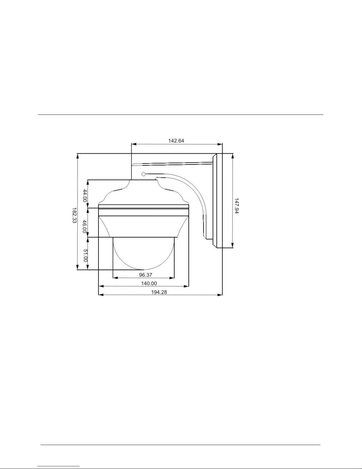
A mini dome camera supports wall-mounted and suspension installation modes. Figure
2-1 shows mounting bracket and suspension installation modes, as shown in Figure
2-2.
To prevent the water flow into the dome camera, please make sure that the multi-head cable
is not exposed.
The following describes how to install a dome camera in wall-mounted mode.
Page 12
Error! Use the Home tab to apply 标题
1,heading 1,h:1,h:1app,level 1,Level 1
Head,H1,h1,Huvudrubrik,Title1,l1,1st
level,Section Head,Sec1,h11,1st level1,h12,1st
level2,h13,1st level3,h14,1st level4,h15,1st
level5,h16,1st level6,h17,1st level7,h18,1st
level8,h111,1Error! Use the Home tab to apply 标
题 1,heading 1,h:1,h:1app,level 1,Level 1
Head,H1,h1,Huvudrubrik,Title1,l1,1st
level,Section Head,Sec1,h11,1st level1,h12,1st
level2,h13,1st level3,h14,1st level4,h15,1st
level5,h16,1st level6,h17,1st level7,h18,1st
level8,h111,1
Network High Speed Mini Dome
User Manual
4 Issue V1.0 (2014-06-10)
Figure 2-1 Mounting bracket (unit: mm)
Page 13

Network High Speed Mini Dome
User Manual
Error! Use the Home tab to apply 标题
1,heading 1,h:1,h:1app,level 1,Level 1
Head,H1,h1,Huvudrubrik,Title1,l1,1st
level,Section Head,Sec1,h11,1st level1,h12,1st
level2,h13,1st level3,h14,1st level4,h15,1st
level5,h16,1st level6,h17,1st level7,h18,1st
level8,h111,1Error! Use the Home tab to apply 标
题 1,heading 1,h:1,h:1app,level 1,Level 1
Head,H1,h1,Huvudrubrik,Title1,l1,1st
level,Section Head,Sec1,h11,1st level1,h12,1st
level2,h13,1st level3,h14,1st level4,h15,1st
level5,h16,1st level6,h17,1st level7,h18,1st
level8,h111,1
Issue V1.0 (2014-06-10) 5
Figure 2-2 Suspension installation (unit: mm)
2.1.1 Installing a Dome in a wall-mounting Mode
Open the package and carefully take out the dome camera and accessories.
Procedure
Step 1 Determine the positions of installation holes based on the installation dimensions of the
bracket and mark the holes. Use a percussion drill bit with a diameter of 8 mm to drill
four holes that are 60 mm deep.
Step 2 Drive four expansion bolts into the holes.
Page 14

Error! Use the Home tab to apply 标题
1,heading 1,h:1,h:1app,level 1,Level 1
Head,H1,h1,Huvudrubrik,Title1,l1,1st
level,Section Head,Sec1,h11,1st level1,h12,1st
level2,h13,1st level3,h14,1st level4,h15,1st
level5,h16,1st level6,h17,1st level7,h18,1st
level8,h111,1Error! Use the Home tab to apply 标
题 1,heading 1,h:1,h:1app,level 1,Level 1
Head,H1,h1,Huvudrubrik,Title1,l1,1st
level,Section Head,Sec1,h11,1st level1,h12,1st
level2,h13,1st level3,h14,1st level4,h15,1st
level5,h16,1st level6,h17,1st level7,h18,1st
level8,h111,1
Network High Speed Mini Dome
User Manual
6 Issue V1.0 (2014-06-10)
Step 3 Align the dome IPC with the bracket. Mount the IPC on the bracket and rotate the IPC
clockwise so that the holes on the bracket are aligned with the screw holes on the
installation base of the IPC. Then, lock four screws between the bracket and the IPC, as
shown in Figure 2-3.
Figure 2-3 Fixing the main body of the high-speed dome IPC onto the bracket
Step 4 Remove protective vinyl sheet from the dome cover, as shown in Figure 2-4.
Page 15

Network High Speed Mini Dome
User Manual
Error! Use the Home tab to apply 标题
1,heading 1,h:1,h:1app,level 1,Level 1
Head,H1,h1,Huvudrubrik,Title1,l1,1st
level,Section Head,Sec1,h11,1st level1,h12,1st
level2,h13,1st level3,h14,1st level4,h15,1st
level5,h16,1st level6,h17,1st level7,h18,1st
level8,h111,1Error! Use the Home tab to apply 标
题 1,heading 1,h:1,h:1app,level 1,Level 1
Head,H1,h1,Huvudrubrik,Title1,l1,1st
level,Section Head,Sec1,h11,1st level1,h12,1st
level2,h13,1st level3,h14,1st level4,h15,1st
level5,h16,1st level6,h17,1st level7,h18,1st
level8,h111,1
Issue V1.0 (2014-06-10) 7
Figure 2-4 Removing the protective vinyl sheet
----End
2.1.2 Installing the IPC on the Ceiling
Step 1 Determine the positions of installation holes on the ceiling based on the installation
dimensions of the bracket and mark the holes. Use a percussion drill bit with a diameter
of 8 mm to drill four holes that are 60 mm deep.
Step 2 Drive four expansion bolts into the holes.
Step 3 Align the dome IPC with the bracket. Mount the IPC on the bracket and rotate the IPC
clockwise so that the holes on the bracket are aligned with the screw holes on the
installation base of the IPC. Then, lock three screws between the bracket and the IPC,
as shown in Figure 2-5.
Page 16

Error! Use the Home tab to apply 标题
1,heading 1,h:1,h:1app,level 1,Level 1
Head,H1,h1,Huvudrubrik,Title1,l1,1st
level,Section Head,Sec1,h11,1st level1,h12,1st
level2,h13,1st level3,h14,1st level4,h15,1st
level5,h16,1st level6,h17,1st level7,h18,1st
level8,h111,1Error! Use the Home tab to apply 标
题 1,heading 1,h:1,h:1app,level 1,Level 1
Head,H1,h1,Huvudrubrik,Title1,l1,1st
level,Section Head,Sec1,h11,1st level1,h12,1st
level2,h13,1st level3,h14,1st level4,h15,1st
level5,h16,1st level6,h17,1st level7,h18,1st
level8,h111,1
Network High Speed Mini Dome
User Manual
8 Issue V1.0 (2014-06-10)
Figure 2-5 Fixing the main body of the high-speed dome IPC onto the bracket
Step 4 Remove protective vinyl sheet from the dome cover, as shown in Figure 2-6.
Page 17

Network High Speed Mini Dome
User Manual
Error! Use the Home tab to apply 标题
1,heading 1,h:1,h:1app,level 1,Level 1
Head,H1,h1,Huvudrubrik,Title1,l1,1st
level,Section Head,Sec1,h11,1st level1,h12,1st
level2,h13,1st level3,h14,1st level4,h15,1st
level5,h16,1st level6,h17,1st level7,h18,1st
level8,h111,1Error! Use the Home tab to apply 标
题 1,heading 1,h:1,h:1app,level 1,Level 1
Head,H1,h1,Huvudrubrik,Title1,l1,1st
level,Section Head,Sec1,h11,1st level1,h12,1st
level2,h13,1st level3,h14,1st level4,h15,1st
level5,h16,1st level6,h17,1st level7,h18,1st
level8,h111,1
Issue V1.0 (2014-06-10) 9
Figure 2-6 Removing the protective vinyl sheet
----End
Page 18

Error! Use the Home tab to apply 标题
1,heading 1,h:1,h:1app,level 1,Level 1
Head,H1,h1,Huvudrubrik,Title1,l1,1st
level,Section Head,Sec1,h11,1st level1,h12,1st
level2,h13,1st level3,h14,1st level4,h15,1st
level5,h16,1st level6,h17,1st level7,h18,1st
level8,h111,1Error! Use the Home tab to apply 标
题 1,heading 1,h:1,h:1app,level 1,Level 1
Head,H1,h1,Huvudrubrik,Title1,l1,1st
level,Section Head,Sec1,h11,1st level1,h12,1st
level2,h13,1st level3,h14,1st level4,h15,1st
level5,h16,1st level6,h17,1st level7,h18,1st
level8,h111,1
Network High Speed Mini Dome
User Manual
10 Issue V1.0 (2014-06-10)
3 Quick Configuration
3.1 Login and Logout
You must use Internet Explorer 6 or a later version to access the web management
system; otherwise, some functions may be unavailable.
Login system
Step 1 Open the Internet Explorer, enter the IP address of IP camera (default value:
192.168.0.120) in the address box, and press Enter.
The login page is displayed, as shown in Figure 3-1.
Page 19

Network High Speed Mini Dome
User Manual
Error! Use the Home tab to apply 标题
1,heading 1,h:1,h:1app,level 1,Level 1
Head,H1,h1,Huvudrubrik,Title1,l1,1st
level,Section Head,Sec1,h11,1st level1,h12,1st
level2,h13,1st level3,h14,1st level4,h15,1st
level5,h16,1st level6,h17,1st level7,h18,1st
level8,h111,1Error! Use the Home tab to apply 标
题 1,heading 1,h:1,h:1app,level 1,Level 1
Head,H1,h1,Huvudrubrik,Title1,l1,1st
level,Section Head,Sec1,h11,1st level1,h12,1st
level2,h13,1st level3,h14,1st level4,h15,1st
level5,h16,1st level6,h17,1st level7,h18,1st
level8,h111,1
Issue V1.0 (2014-06-10) 11
Figure 3-1 Login page
Step 2 Input the User and password.
The default name is admin. The default password is admin. Change the password when
you log in the system for first time to ensure system security.
You can change the system display language on the login page.
Step 3 Click Login.
The main page is displayed.
----End
logout
To logout of system, click Sign out in the upper right corner of the main page, the login
page is display after you log out of the system.
3.2 Main page layout
On the main page, you can view real-time video, set parameter, Video parameter, Video
control, PTZ control, PTZ Configure and log out of the system. Figure 3-2 is shown the
main page layout.
Page 20

Error! Use the Home tab to apply 标题
1,heading 1,h:1,h:1app,level 1,Level 1
Head,H1,h1,Huvudrubrik,Title1,l1,1st
level,Section Head,Sec1,h11,1st level1,h12,1st
level2,h13,1st level3,h14,1st level4,h15,1st
level5,h16,1st level6,h17,1st level7,h18,1st
level8,h111,1Error! Use the Home tab to apply 标
题 1,heading 1,h:1,h:1app,level 1,Level 1
Head,H1,h1,Huvudrubrik,Title1,l1,1st
level,Section Head,Sec1,h11,1st level1,h12,1st
level2,h13,1st level3,h14,1st level4,h15,1st
level5,h16,1st level6,h17,1st level7,h18,1st
level8,h111,1
Network High Speed Mini Dome
User Manual
12 Issue V1.0 (2014-06-10)
Figure 3-2 Main page layout
Table 3-1 Elements on the main page
N
O.
Element
Description
1
Real-time video
area
Real-time videos are displayed in this area, You can also
set sensor parameters.
2
Menu area
You can choose a menu to set device parameters,
including the device information, video streams, alarm
setting, and privacy mask function.
3
Video area
Video parameters, such as the I frame interval, bit rate
type, bit rate, and quality, are display.
4
Video control
area
You can perform the following operation in this area:
Switch between cameras.
Page 21

Network High Speed Mini Dome
User Manual
Error! Use the Home tab to apply 标题
1,heading 1,h:1,h:1app,level 1,Level 1
Head,H1,h1,Huvudrubrik,Title1,l1,1st
level,Section Head,Sec1,h11,1st level1,h12,1st
level2,h13,1st level3,h14,1st level4,h15,1st
level5,h16,1st level6,h17,1st level7,h18,1st
level8,h111,1Error! Use the Home tab to apply 标
题 1,heading 1,h:1,h:1app,level 1,Level 1
Head,H1,h1,Huvudrubrik,Title1,l1,1st
level,Section Head,Sec1,h11,1st level1,h12,1st
level2,h13,1st level3,h14,1st level4,h15,1st
level5,h16,1st level6,h17,1st level7,h18,1st
level8,h111,1
Issue V1.0 (2014-06-10) 13
N
O.
Element
Description
Start or stop playing Videos.
5
PTZ control
You can control the camera direction, zoom in or out, and
change the focal length and aperture for a dome camera or
a camera connected to an external PTZ.
NOTE
Currently the automatic aperture adjustment function is not
support.
6
PTZ
configuration
area
you can perform the following operation in this area:
Add, delete, and invoke the presents and tacks.
Adjust the PTZ rotation speed.
Enable or disable 3D position.
Set the direction to due north.
Set the PTZ timer.
NOTE
PTZ timer function as a time trigger. When it is activated,
the PTZ rotates according to presents and tracks as
scheduled.
The PTZ timer use the time set in camera. Ensure the time is
correct.
This function is available only to a camera with PTZ or
camera connected to external PTZ.
7
Sign out
You can click this button to return to the login page.
8
Change
password
You can click this button to change the password.
9
Fault icon
When the device encounters an exception, the fault icon
is displayed. You can click to view the fault
information.
10
Alarm icon
When the device generates an alarm, the alarm icon
is displayed. You can click to view the alarm
Page 22

Error! Use the Home tab to apply 标题
1,heading 1,h:1,h:1app,level 1,Level 1
Head,H1,h1,Huvudrubrik,Title1,l1,1st
level,Section Head,Sec1,h11,1st level1,h12,1st
level2,h13,1st level3,h14,1st level4,h15,1st
level5,h16,1st level6,h17,1st level7,h18,1st
level8,h111,1Error! Use the Home tab to apply 标
题 1,heading 1,h:1,h:1app,level 1,Level 1
Head,H1,h1,Huvudrubrik,Title1,l1,1st
level,Section Head,Sec1,h11,1st level1,h12,1st
level2,h13,1st level3,h14,1st level4,h15,1st
level5,h16,1st level6,h17,1st level7,h18,1st
level8,h111,1
Network High Speed Mini Dome
User Manual
14 Issue V1.0 (2014-06-10)
N
O.
Element
Description
information.
Note
When the device accepts an alarm signal, the alarm icon will
display within 10s in the web management system.
3.3 Browsing Video
User can browse the real-time video in the web management system.
Preparation
To ensure the real-time video can be play properly, you must perform the following
operation when you log in to the web for the first time:
1. Open the Internet Explorer. Choose Tools > Internet options > Security >
Trusted sites > Sites.
In the display dialog box, click Add, as shown in Figure 3-3.
Page 23

Network High Speed Mini Dome
User Manual
Error! Use the Home tab to apply 标题
1,heading 1,h:1,h:1app,level 1,Level 1
Head,H1,h1,Huvudrubrik,Title1,l1,1st
level,Section Head,Sec1,h11,1st level1,h12,1st
level2,h13,1st level3,h14,1st level4,h15,1st
level5,h16,1st level6,h17,1st level7,h18,1st
level8,h111,1Error! Use the Home tab to apply 标
题 1,heading 1,h:1,h:1app,level 1,Level 1
Head,H1,h1,Huvudrubrik,Title1,l1,1st
level,Section Head,Sec1,h11,1st level1,h12,1st
level2,h13,1st level3,h14,1st level4,h15,1st
level5,h16,1st level6,h17,1st level7,h18,1st
level8,h111,1
Issue V1.0 (2014-06-10) 15
Figure 3-3 Adding the a trusted site
2. In the Internet Explorer, choose Tool > Internet Options > Security > Customer
level, and set Download unsigned ActiveX control and initialize and script ActiveX
controls not marked as safe for scripting under ActiveX controls and plug-ins to
Enable, as shown in Figure 3-4.
Page 24

Error! Use the Home tab to apply 标题
1,heading 1,h:1,h:1app,level 1,Level 1
Head,H1,h1,Huvudrubrik,Title1,l1,1st
level,Section Head,Sec1,h11,1st level1,h12,1st
level2,h13,1st level3,h14,1st level4,h15,1st
level5,h16,1st level6,h17,1st level7,h18,1st
level8,h111,1Error! Use the Home tab to apply 标
题 1,heading 1,h:1,h:1app,level 1,Level 1
Head,H1,h1,Huvudrubrik,Title1,l1,1st
level,Section Head,Sec1,h11,1st level1,h12,1st
level2,h13,1st level3,h14,1st level4,h15,1st
level5,h16,1st level6,h17,1st level7,h18,1st
level8,h111,1
Network High Speed Mini Dome
User Manual
16 Issue V1.0 (2014-06-10)
Figure 3-4 Configuring ActiveX control and plug-ins
3. Download and install the player control as prompted.
The login page is display when the control is loaded.
3.3.1 Download the right control in the Internet Explorer
Preparation
User uses the Internet Explorer browse video.
Real-time video page pop-ups the message “clicks to play live video with ActiveX
control to reduce latency” as shown in Figure 3-5.
Page 25

Network High Speed Mini Dome
User Manual
Error! Use the Home tab to apply 标题
1,heading 1,h:1,h:1app,level 1,Level 1
Head,H1,h1,Huvudrubrik,Title1,l1,1st
level,Section Head,Sec1,h11,1st level1,h12,1st
level2,h13,1st level3,h14,1st level4,h15,1st
level5,h16,1st level6,h17,1st level7,h18,1st
level8,h111,1Error! Use the Home tab to apply 标
题 1,heading 1,h:1,h:1app,level 1,Level 1
Head,H1,h1,Huvudrubrik,Title1,l1,1st
level,Section Head,Sec1,h11,1st level1,h12,1st
level2,h13,1st level3,h14,1st level4,h15,1st
level5,h16,1st level6,h17,1st level7,h18,1st
level8,h111,1
Issue V1.0 (2014-06-10) 17
Figure 3-5 Change the ActiveX
Click the message, jump to download ActiveX control interface, once downloading is
complete, you can watch more fluent video screen.
Uable to display video picture, and need to download and install the control
Preparation
User uses the IE Explorer browse video.
Real-time video page pop-up the message “click to download the latest version of
Flash Play live video” and “click to play video with ActiveX control to reduce
latency” as shown in Figure 3-6.
Page 26

Error! Use the Home tab to apply 标题
1,heading 1,h:1,h:1app,level 1,Level 1
Head,H1,h1,Huvudrubrik,Title1,l1,1st
level,Section Head,Sec1,h11,1st level1,h12,1st
level2,h13,1st level3,h14,1st level4,h15,1st
level5,h16,1st level6,h17,1st level7,h18,1st
level8,h111,1Error! Use the Home tab to apply 标
题 1,heading 1,h:1,h:1app,level 1,Level 1
Head,H1,h1,Huvudrubrik,Title1,l1,1st
level,Section Head,Sec1,h11,1st level1,h12,1st
level2,h13,1st level3,h14,1st level4,h15,1st
level5,h16,1st level6,h17,1st level7,h18,1st
level8,h111,1
Network High Speed Mini Dome
User Manual
18 Issue V1.0 (2014-06-10)
Figure 3-6 Download control tips
Click the message” click to play live video with ActiveX control to reduce latency”,
jump download Adobe Flash Player Plugin control interface, once downloading is
complete, you can watch video screen.
Click the message “click to download the latest version of Flash Play live video”, jump
to download ActiveX control interface, once downloading is complete, you can watch
more fluent video screen.
3.3.2 In the Google, Firefox, or Safari browsers watch real-time
video
Google, Firefox, and Safari browsers only support Adobe Flash Player Plugin to play
video. When Adobe Flash Plugin control version is too low, browser will automatically
clew you to download the latest control.
Page 27

Network High Speed Mini Dome
User Manual
Error! Use the Home tab to apply 标题
1,heading 1,h:1,h:1app,level 1,Level 1
Head,H1,h1,Huvudrubrik,Title1,l1,1st
level,Section Head,Sec1,h11,1st level1,h12,1st
level2,h13,1st level3,h14,1st level4,h15,1st
level5,h16,1st level6,h17,1st level7,h18,1st
level8,h111,1Error! Use the Home tab to apply 标
题 1,heading 1,h:1,h:1app,level 1,Level 1
Head,H1,h1,Huvudrubrik,Title1,l1,1st
level,Section Head,Sec1,h11,1st level1,h12,1st
level2,h13,1st level3,h14,1st level4,h15,1st
level5,h16,1st level6,h17,1st level7,h18,1st
level8,h111,1
Issue V1.0 (2014-06-10) 19
3.4 Setting Local Network Parameters
Description
Local network parameters include:
IP protocol
IP address
Subnet mask
Default gateway
Dynamic Host Configuration Protocol (DHCP)
Preferred Domain Name System (DNS) server
Alternate DNS server
Procedure
Choose Device Configuration > Local Network.
The Local Network page is displayed, as shown in Figure 3-7.
Page 28

Error! Use the Home tab to apply 标题
1,heading 1,h:1,h:1app,level 1,Level 1
Head,H1,h1,Huvudrubrik,Title1,l1,1st
level,Section Head,Sec1,h11,1st level1,h12,1st
level2,h13,1st level3,h14,1st level4,h15,1st
level5,h16,1st level6,h17,1st level7,h18,1st
level8,h111,1Error! Use the Home tab to apply 标
题 1,heading 1,h:1,h:1app,level 1,Level 1
Head,H1,h1,Huvudrubrik,Title1,l1,1st
level,Section Head,Sec1,h11,1st level1,h12,1st
level2,h13,1st level3,h14,1st level4,h15,1st
level5,h16,1st level6,h17,1st level7,h18,1st
level8,h111,1
Network High Speed Mini Dome
User Manual
20 Issue V1.0 (2014-06-10)
Figure 3-7 Local Network page
Step 4 Set the parameters according to Table 3-2.
Page 29

Network High Speed Mini Dome
User Manual
Error! Use the Home tab to apply 标题
1,heading 1,h:1,h:1app,level 1,Level 1
Head,H1,h1,Huvudrubrik,Title1,l1,1st
level,Section Head,Sec1,h11,1st level1,h12,1st
level2,h13,1st level3,h14,1st level4,h15,1st
level5,h16,1st level6,h17,1st level7,h18,1st
level8,h111,1Error! Use the Home tab to apply 标
题 1,heading 1,h:1,h:1app,level 1,Level 1
Head,H1,h1,Huvudrubrik,Title1,l1,1st
level,Section Head,Sec1,h11,1st level1,h12,1st
level2,h13,1st level3,h14,1st level4,h15,1st
level5,h16,1st level6,h17,1st level7,h18,1st
level8,h111,1
Issue V1.0 (2014-06-10) 21
Table 3-2 Local network parameters
Parameter
Description
Setting
IP Protocol
IPv4 is the IP protocol that uses
an address length of 32 bits.
[Setting method]
Select a value from the
drop-down list box.
[Default value]
IPv4
Device obtain an
IP address
automatically
The device automatically
obtains the IP address from the
DHCP server.
[Setting method]
Click the option button.
NOTE
To query the current IP
address of the device, you
must query it on the
platform based on the
device name.
DHCP IP
IP address that the DHCP server
assigned to the device.
N/A
IP Address
Device IP address that can be
set as required.
[Setting method]
Enter a value manually.
[Default value]
192.168.0.120
Subnet Mask
Subnet mask of the network
adapter.
[Setting method]
Enter a value manually.
[Default value]
255.255.255.0
Default Gateway
This parameter must be set if
the client accesses the device
through a gateway.
[Setting method]
Enter a value manually.
[Default value]
192.168.0.1
Page 30

Error! Use the Home tab to apply 标题
1,heading 1,h:1,h:1app,level 1,Level 1
Head,H1,h1,Huvudrubrik,Title1,l1,1st
level,Section Head,Sec1,h11,1st level1,h12,1st
level2,h13,1st level3,h14,1st level4,h15,1st
level5,h16,1st level6,h17,1st level7,h18,1st
level8,h111,1Error! Use the Home tab to apply 标
题 1,heading 1,h:1,h:1app,level 1,Level 1
Head,H1,h1,Huvudrubrik,Title1,l1,1st
level,Section Head,Sec1,h11,1st level1,h12,1st
level2,h13,1st level3,h14,1st level4,h15,1st
level5,h16,1st level6,h17,1st level7,h18,1st
level8,h111,1
Network High Speed Mini Dome
User Manual
22 Issue V1.0 (2014-06-10)
Parameter
Description
Setting
Preferred DNS
Server
IP address of a DNS server.
[Setting method]
Enter a value manually.
[Default value]
192.168.0.1
Alternate DNS
Server
IP address of a domain server.
If the preferred DNS server is
faulty, the device uses the
alternate DNS server to resolve
domain names.
[Setting method]
Enter a value manually.
[Default value]
192.168.0.2
MTU
Set the maximum value of
network transmission data
packets.
[Setting method]
Enter a value manually.
NOTE
The MTU value is range
from 800 to 1500, the
default value is 1380,
Please do not change it
arbitrarily.
Step 5 Click OK.
If the message "Network Parameter Updated" is displayed, click OK. The system
saves the settings. The message "Set network params success, Please login system
again" is displayed. Use the new IP address to log in to the web management
system.
If the message "Invalid IP Address", "Invalid Subnet Mask", "Invalid default
gateway", "Invalid primary DNS", or "Invalid space DNS" is displayed, set the
parameters correctly.
If you set only the Subnet Mask, Default Gateway, Preferred DNS Server, and
Alternate DNS Server parameters, you do not need to log in to the system again.
You can click Reset to set the parameters again if required.
----End
Page 31

Network High Speed Mini Dome
User Manual
Error! Use the Home tab to apply 标题
1,heading 1,h:1,h:1app,level 1,Level 1
Head,H1,h1,Huvudrubrik,Title1,l1,1st
level,Section Head,Sec1,h11,1st level1,h12,1st
level2,h13,1st level3,h14,1st level4,h15,1st
level5,h16,1st level6,h17,1st level7,h18,1st
level8,h111,1Error! Use the Home tab to apply 标
题 1,heading 1,h:1,h:1app,level 1,Level 1
Head,H1,h1,Huvudrubrik,Title1,l1,1st
level,Section Head,Sec1,h11,1st level1,h12,1st
level2,h13,1st level3,h14,1st level4,h15,1st
level5,h16,1st level6,h17,1st level7,h18,1st
level8,h111,1
Issue V1.0 (2014-06-10) 23
4 Function Menus
4.1 OSD Menu
You can do personalized settings, such as the Preset position, Intermittent Cruise,
Regional Cruise (Cruising between Points), Preset Cruise (group cruise), Auto Cruise,
and other features.
Call Preset 95 to open OSD menu.
4.2 Preset Retention
Some of the presets can be reserved for the special use, see in Table 4-1.
Table 4-1 Call the PTZ camera’s particular preset
Preset
Description
Call 95 preset
Enter the OSD menu
Call 83 preset
Clear all presets
Call 96 preset
360 Intermittent cruise
Call 97 preset
Regional cruise (cruising between points): Area
between two preset cruise
Call 82/98 presets
Preset cruise (Group Cruise)
Call 99 preset
360 auto cruise
4.3 Preset
A maximum of 256 presets can be configured.
Set Preset
Page 32

Error! Use the Home tab to apply 标题
1,heading 1,h:1,h:1app,level 1,Level 1
Head,H1,h1,Huvudrubrik,Title1,l1,1st
level,Section Head,Sec1,h11,1st level1,h12,1st
level2,h13,1st level3,h14,1st level4,h15,1st
level5,h16,1st level6,h17,1st level7,h18,1st
level8,h111,1Error! Use the Home tab to apply 标
题 1,heading 1,h:1,h:1app,level 1,Level 1
Head,H1,h1,Huvudrubrik,Title1,l1,1st
level,Section Head,Sec1,h11,1st level1,h12,1st
level2,h13,1st level3,h14,1st level4,h15,1st
level5,h16,1st level6,h17,1st level7,h18,1st
level8,h111,1
Network High Speed Mini Dome
User Manual
24 Issue V1.0 (2014-06-10)
Set Preset [1~256].
Run Preset
Call Preset [1~256].
Delete Preset
Call Preset 83 to clear all presets.
4.4 Intermittent Cruise
Run to do the 360 auto cruise in the horizontal direction at a constant speed intermittent
cruise, speed from 1(Slowest) to 32(Fastest).
Set Intermittent Cruise
Use OSD to set Intermittent Cruise.
Call Intermittent Cruise
Call Preset 96 to Intermittent Cruise.
4.5 Regional Cruise (Cruising between points)
Move the camera loop between two preset positions. Camera clockwise move from the
first preset to the second preset, and also move from the second point in the
counterclockwise direction back to the first point. Speeds range from 1 (slowest) to 32
(fastest).
Figure 4-1 Regional cruise (cruising between points)
Page 33

Network High Speed Mini Dome
User Manual
Error! Use the Home tab to apply 标题
1,heading 1,h:1,h:1app,level 1,Level 1
Head,H1,h1,Huvudrubrik,Title1,l1,1st
level,Section Head,Sec1,h11,1st level1,h12,1st
level2,h13,1st level3,h14,1st level4,h15,1st
level5,h16,1st level6,h17,1st level7,h18,1st
level8,h111,1Error! Use the Home tab to apply 标
题 1,heading 1,h:1,h:1app,level 1,Level 1
Head,H1,h1,Huvudrubrik,Title1,l1,1st
level,Section Head,Sec1,h11,1st level1,h12,1st
level2,h13,1st level3,h14,1st level4,h15,1st
level5,h16,1st level6,h17,1st level7,h18,1st
level8,h111,1
Issue V1.0 (2014-06-10) 25
Set Regional cruise (cruising between points): 1 group
Use the OSD menu to set the Regional cruise (cruising between points).
Run Regional cruise (cruising between points):
Call number 97 Preset.
Delete Regional cruise (cruising between points)
Use the OSD menu to delete.
4.6 Preset Cruise (Group Cruise)
Run the Preset: You can adjust the order, the largest store 10 preset positions, dwell
time can be adjusted between presets, ranging from 5 to 250 seconds. As shown in
Figure 4-2.
Figure 4-2 Preset Cruise (Group Cruise)
Set preset cruise (Group Cruise): A total of three groups
Use the OSD menu to set preset cruise (group cruise).
Run preset cruise (Group Cruise):
Call number 82 or number 98 presets.
Delete preset cruise (Group Cruise)
Use the OSD menu to delete.
Page 34

Error! Use the Home tab to apply 标题
1,heading 1,h:1,h:1app,level 1,Level 1
Head,H1,h1,Huvudrubrik,Title1,l1,1st
level,Section Head,Sec1,h11,1st level1,h12,1st
level2,h13,1st level3,h14,1st level4,h15,1st
level5,h16,1st level6,h17,1st level7,h18,1st
level8,h111,1Error! Use the Home tab to apply 标
题 1,heading 1,h:1,h:1app,level 1,Level 1
Head,H1,h1,Huvudrubrik,Title1,l1,1st
level,Section Head,Sec1,h11,1st level1,h12,1st
level2,h13,1st level3,h14,1st level4,h15,1st
level5,h16,1st level6,h17,1st level7,h18,1st
level8,h111,1
Network High Speed Mini Dome
User Manual
26 Issue V1.0 (2014-06-10)
4.7 Auto Cruise
The camera can autorun horizontally cruise at a speed of 360-degree continuous cyclic
scanning.
Set Auto Cruise
Do not need to set up, the system has been set.
Call Auto Cruise
Call Preset 99.
4.8 Other Functions
POWER UP Action
Auto-run specified action after power on. Actions include: Auto Cruise, Intermittent
Cruise, Regional Cruise (Between points Cruise), Preset 1, Preset 8, Preset cruise
(group cruise).
PARK ACTION
This feature allows the camera automatically placed in a specific location. If the
camera is not operated temporarily, it will run automatically the specified action.
Actions include: Auto Cruise, Intermittent Cruise, Regional Cruise (Between points
Cruise), Preset 1, Preset 8, revert to the most recent action, Preset cruise (Group
cruise). The idle time can be defined,from 5 to 250 seconds.
4.9 General Rules of Menu Operation
Use UP/DOWN to select each submenu.
Press IRIS+ to enter the submenu.
Press IRIS+ button to go return when UP/DOWN to the BACK option.
Use UP/DOWN or LEFT/RIGHT to change settings.
Exit the menu: Use the UP / DOWN buttons to select EXIT, or press IRIS-key.
Page 35

Network High Speed Mini Dome
User Manual
Error! Use the Home tab to apply 标题
1,heading 1,h:1,h:1app,level 1,Level 1
Head,H1,h1,Huvudrubrik,Title1,l1,1st
level,Section Head,Sec1,h11,1st level1,h12,1st
level2,h13,1st level3,h14,1st level4,h15,1st
level5,h16,1st level6,h17,1st level7,h18,1st
level8,h111,1Error! Use the Home tab to apply 标
题 1,heading 1,h:1,h:1app,level 1,Level 1
Head,H1,h1,Huvudrubrik,Title1,l1,1st
level,Section Head,Sec1,h11,1st level1,h12,1st
level2,h13,1st level3,h14,1st level4,h15,1st
level5,h16,1st level6,h17,1st level7,h18,1st
level8,h111,1
Issue V1.0 (2014-06-10) 27
4.9.1 MAIN MENU
The OSD main menu is displayed as shown in Figure 4-3.
Figure 4-3 Main menu
Table 4-2 describes the function options on the OSD main menu.
Table 4-2 OSD Main Menu Description
Name
Description
SYSTEM
INFORMATION
System Information Display.
MOTION
PTZ settings.
CAMERA
Camera settings.
CRUISE SETTING
Preset cruise (group cruise) settings.
RESTORE
FACTORY
DEFAULT
Reset the PTZ, restore to the factory default settings.
REBOOT SYSTEM
System restart, to re-power-on reset.
EXIT
Exit the menu.
Page 36

Error! Use the Home tab to apply 标题
1,heading 1,h:1,h:1app,level 1,Level 1
Head,H1,h1,Huvudrubrik,Title1,l1,1st
level,Section Head,Sec1,h11,1st level1,h12,1st
level2,h13,1st level3,h14,1st level4,h15,1st
level5,h16,1st level6,h17,1st level7,h18,1st
level8,h111,1Error! Use the Home tab to apply 标
题 1,heading 1,h:1,h:1app,level 1,Level 1
Head,H1,h1,Huvudrubrik,Title1,l1,1st
level,Section Head,Sec1,h11,1st level1,h12,1st
level2,h13,1st level3,h14,1st level4,h15,1st
level5,h16,1st level6,h17,1st level7,h18,1st
level8,h111,1
Network High Speed Mini Dome
User Manual
28 Issue V1.0 (2014-06-10)
4.9.2 SYSTEM INFORMATION
System Information menu: Displays basic information, as shown in Figure 4-4.
Figure 4-4 System Information menu
Table 4-3 describes the function options on the system information menu.
Table 4-3 System Information Description
Name
Description
COM
Serial information: Displayed baud rate , parity, data bits,
stop bits of the serial port.
ADDRESS
Dome address, show the address coding.
PORTOCOL
PELCO-D
Control protocol, display Communication Protocol
PRESETS
Display preset number.
SOFTWARE
VERSION
Software version.
BACK
Return to the main menu.
EXIT
Exit menu settings.
Page 37

Network High Speed Mini Dome
User Manual
Error! Use the Home tab to apply 标题
1,heading 1,h:1,h:1app,level 1,Level 1
Head,H1,h1,Huvudrubrik,Title1,l1,1st
level,Section Head,Sec1,h11,1st level1,h12,1st
level2,h13,1st level3,h14,1st level4,h15,1st
level5,h16,1st level6,h17,1st level7,h18,1st
level8,h111,1Error! Use the Home tab to apply 标
题 1,heading 1,h:1,h:1app,level 1,Level 1
Head,H1,h1,Huvudrubrik,Title1,l1,1st
level,Section Head,Sec1,h11,1st level1,h12,1st
level2,h13,1st level3,h14,1st level4,h15,1st
level5,h16,1st level6,h17,1st level7,h18,1st
level8,h111,1
Issue V1.0 (2014-06-10) 29
4.9.3 MOTION
PTZ setup menu is displayed as shown in Figure 4-5.
Figure 4-5 PTZ setup menu
Table 4-4 describes the function options on the PTZ setup instructions menu.
Table 4-4 PTZ setup instructions
Name
Description
SET FRAME SCAN
Set the starting position and end position of Regional
Cruise (Cruising between points).
POWER UP
Power-action setting. Actions include:
NONE: No action;
AUTO SCAN: auto cruise;
RANDOM SCAN: Intermittent cruise;
FRAME SCAN:Regional cruise (cruising between
points)
PRESET1:Preset 1;
PRESET8:Preset 8;
CRUISE:Preset cruise (group cruise).
PARK TIME
Idle time setting, 0~ 255 seconds.
PARK ACTION
Power-action setting. Actions include:
NONE: No action;
Page 38

Error! Use the Home tab to apply 标题
1,heading 1,h:1,h:1app,level 1,Level 1
Head,H1,h1,Huvudrubrik,Title1,l1,1st
level,Section Head,Sec1,h11,1st level1,h12,1st
level2,h13,1st level3,h14,1st level4,h15,1st
level5,h16,1st level6,h17,1st level7,h18,1st
level8,h111,1Error! Use the Home tab to apply 标
题 1,heading 1,h:1,h:1app,level 1,Level 1
Head,H1,h1,Huvudrubrik,Title1,l1,1st
level,Section Head,Sec1,h11,1st level1,h12,1st
level2,h13,1st level3,h14,1st level4,h15,1st
level5,h16,1st level6,h17,1st level7,h18,1st
level8,h111,1
Network High Speed Mini Dome
User Manual
30 Issue V1.0 (2014-06-10)
Name
Description
AUTO SCAN: auto cruise;
RANDOM SCAN: Intermittent cruise;
FRAME SCAN:Regional cruise (cruising between
points)
PRESET1:PRESET1;
PRESET8:PRESET8;
REAPEAT LAST:Return to action recently;
CRUISE:Preset cruise (group cruise).
FRAME SCAN
SPEED
Set the speed of Regional cruise (cruising between
points), speed from 1(Slowest) to 32(Fastest).
RANDOM SCAN
SPEED
Set Intermittent Cruise, speed from 1(Slowest) to
32(Fastest).
BACK
Return Main menu
EXIT
Exit Menu
4.9.4 CAMERA Settings
Camera menu operation rules:
Use the UP / DOWN keys to select.
Use LEFT / RIGHT keys to change the value of some function.
Use IRIS + button or wait 30 seconds automatically return to previous menu (PTZ
menu).
Page 39

Network High Speed Mini Dome
User Manual
Error! Use the Home tab to apply 标题
1,heading 1,h:1,h:1app,level 1,Level 1
Head,H1,h1,Huvudrubrik,Title1,l1,1st
level,Section Head,Sec1,h11,1st level1,h12,1st
level2,h13,1st level3,h14,1st level4,h15,1st
level5,h16,1st level6,h17,1st level7,h18,1st
level8,h111,1Error! Use the Home tab to apply 标
题 1,heading 1,h:1,h:1app,level 1,Level 1
Head,H1,h1,Huvudrubrik,Title1,l1,1st
level,Section Head,Sec1,h11,1st level1,h12,1st
level2,h13,1st level3,h14,1st level4,h15,1st
level5,h16,1st level6,h17,1st level7,h18,1st
level8,h111,1
Issue V1.0 (2014-06-10) 31
Camera settings page is displayed as shown in Figure 4-6.
Figure 4-6 Camera Settings
Table 4-5 describes the function options on the camera settings menu.
Table 4-5 Camera settings description
CAMERA MENU A
Name
Description
CAMERA ID
Camera address. Fixed value, cannot be changed.
IRIS
Camera aperture. Fixed value, cannot be changed.
SHUTTER
Electronic shutter. Adjusted value:
1/60,1/120,1/250,1/500,1/1000,1/2000,1/4000,1/10K
AGC
Auto Gain Control. Available AGC options are MAX,
MIDDLE and MIX.
WDR
WDR function. Available WDR options are ON and
OFF.
DNR
DNR function. Available DNR options are ON and OFF.
DAY&NIGHT
Day / night function. Available DAY&NIGHT options
are BW, AGC and COLOR.
FOCUS
Focus mode. Available FOCUS options are MANU,
KEY and AUTO.
BUAD RATE
Communication baud rate, cannot be changed. The
default value is 9600.
Page 40

Error! Use the Home tab to apply 标题
1,heading 1,h:1,h:1app,level 1,Level 1
Head,H1,h1,Huvudrubrik,Title1,l1,1st
level,Section Head,Sec1,h11,1st level1,h12,1st
level2,h13,1st level3,h14,1st level4,h15,1st
level5,h16,1st level6,h17,1st level7,h18,1st
level8,h111,1Error! Use the Home tab to apply 标
题 1,heading 1,h:1,h:1app,level 1,Level 1
Head,H1,h1,Huvudrubrik,Title1,l1,1st
level,Section Head,Sec1,h11,1st level1,h12,1st
level2,h13,1st level3,h14,1st level4,h15,1st
level5,h16,1st level6,h17,1st level7,h18,1st
level8,h111,1
Network High Speed Mini Dome
User Manual
32 Issue V1.0 (2014-06-10)
CAMERA MENU A
Name
Description
NEXT
Next page.
CAMERA MENU B
BRIGHTNESS
Used to set the picture brightness level. The level ranges
from 0 to 127, and the default value is 12.
SHARPNESS
Used to set the picture sharpness level. The level ranges
from 0 to 15, and the default value is 04.
MIRROR
Level mirroring. Available MIRROR options are ON and
OFF.
FLIP
Vertically inverted function. Available FLIP options are
ON and OFF.
NEGATIVE
Negative film image feature. Available NEGATIVE
options are ON and OFF.
OSD
Zoom Lens info settings. Available OSD options are ON
and OFF.
OUTPUT
PAL: 1080/25P; NTSC: 1080/30P. The default value is
1080/25P.
FACTORY
Reset to factory default setting. Available FACTORY
options are ON and OFF.
4.9.5 Preset CRUISE (Group CRUISE) Setting
Preset Cruise (Group Cruise) setting page is displayed as shown in Figure 4-7.
Page 41

Network High Speed Mini Dome
User Manual
Error! Use the Home tab to apply 标题
1,heading 1,h:1,h:1app,level 1,Level 1
Head,H1,h1,Huvudrubrik,Title1,l1,1st
level,Section Head,Sec1,h11,1st level1,h12,1st
level2,h13,1st level3,h14,1st level4,h15,1st
level5,h16,1st level6,h17,1st level7,h18,1st
level8,h111,1Error! Use the Home tab to apply 标
题 1,heading 1,h:1,h:1app,level 1,Level 1
Head,H1,h1,Huvudrubrik,Title1,l1,1st
level,Section Head,Sec1,h11,1st level1,h12,1st
level2,h13,1st level3,h14,1st level4,h15,1st
level5,h16,1st level6,h17,1st level7,h18,1st
level8,h111,1
Issue V1.0 (2014-06-10) 33
Figure 4-7 Preset Cruise (Group Cruise) Setting
Table 4-6 describes the function options on the camera settings menu.
Table 4-6 Preset Cruise (Group Cruise) Setting Description
Name
Description
DWELL
TIME(SECS)
Cruise waiting time between presets,range:5~250
Seconds.
PRESET LIST
Preset cruising list. Total three pages, each can select 10
presets.
1 ON 0 OFF
1234567890
PRESET
0000000000
(1~10)
Select the involved presets,parameters 0 or 1.To change
setting by pressing IRIS+:press 1 for the selection, 0
skipped.
BACK
Return Main Menu
EXIT
Exit OSD setting
4.9.6 RESTORE FACTORY DEFAULT
PTZ reset function. Select after entering: YES or NO. YESAuto reboot and restore
PTZ to factory default setting after waiting about 30 seconds, NO Cancel reset.
Page 42

Error! Use the Home tab to apply 标题
1,heading 1,h:1,h:1app,level 1,Level 1
Head,H1,h1,Huvudrubrik,Title1,l1,1st
level,Section Head,Sec1,h11,1st level1,h12,1st
level2,h13,1st level3,h14,1st level4,h15,1st
level5,h16,1st level6,h17,1st level7,h18,1st
level8,h111,1Error! Use the Home tab to apply 标
题 1,heading 1,h:1,h:1app,level 1,Level 1
Head,H1,h1,Huvudrubrik,Title1,l1,1st
level,Section Head,Sec1,h11,1st level1,h12,1st
level2,h13,1st level3,h14,1st level4,h15,1st
level5,h16,1st level6,h17,1st level7,h18,1st
level8,h111,1
Network High Speed Mini Dome
User Manual
34 Issue V1.0 (2014-06-10)
4.9.7 REBOOT SYSTEM
Reboot system.
Page 43

Network High Speed Mini Dome
User Manual
Error! Use the Home tab to apply 标题
1,heading 1,h:1,h:1app,level 1,Level 1
Head,H1,h1,Huvudrubrik,Title1,l1,1st
level,Section Head,Sec1,h11,1st level1,h12,1st
level2,h13,1st level3,h14,1st level4,h15,1st
level5,h16,1st level6,h17,1st level7,h18,1st
level8,h111,1Error! Use the Home tab to apply 标
题 1,heading 1,h:1,h:1app,level 1,Level 1
Head,H1,h1,Huvudrubrik,Title1,l1,1st
level,Section Head,Sec1,h11,1st level1,h12,1st
level2,h13,1st level3,h14,1st level4,h15,1st
level5,h16,1st level6,h17,1st level7,h18,1st
level8,h111,1
Issue V1.0 (2014-06-10) 35
5 Specifications
Table 5-1 lists the technical specifications of the mini dome.
Table 5-1 Technical specification
Items
Parameters
Specifications
Module
Specific
ations
Sensor
1/2.8 Exmor CMOS Sensor
Pixel
2MP
Resolution
1920×1080
Video Format
PAN:1920×1080p/25fps;NTSC:1920×1080p/30fps
Synchronizati
on
Inter-sync
Lens
4.9mm(wide)–49mm(tele)
Foucus
Auto/Manual/Keyboard
Optical Zoon
10x
Horizontal
viewing angle
Near 53.2°,Far 5.65°
SNR
>50dB
Illumination
0.1Lux/F1.6 (Color), 0.01Lux/F1.6 (Black/White)
Auto-Gain
Low/Mid/High
WDR
On/Off
DNR
On/Off
Day/Night
COLOR,B/W,AGC
Funtions
Horizontal
range
360 degree continuous rotation
Page 44

Error! Use the Home tab to apply 标题
1,heading 1,h:1,h:1app,level 1,Level 1
Head,H1,h1,Huvudrubrik,Title1,l1,1st
level,Section Head,Sec1,h11,1st level1,h12,1st
level2,h13,1st level3,h14,1st level4,h15,1st
level5,h16,1st level6,h17,1st level7,h18,1st
level8,h111,1Error! Use the Home tab to apply 标
题 1,heading 1,h:1,h:1app,level 1,Level 1
Head,H1,h1,Huvudrubrik,Title1,l1,1st
level,Section Head,Sec1,h11,1st level1,h12,1st
level2,h13,1st level3,h14,1st level4,h15,1st
level5,h16,1st level6,h17,1st level7,h18,1st
level8,h111,1
Network High Speed Mini Dome
User Manual
36 Issue V1.0 (2014-06-10)
Items
Parameters
Specifications
Horizontal
speed
0.5-300°/ sec
Vertical range
0-90 degrees, mechanical flip
Preset
256
Preset Speed
300 degrees / sec.
Preset cruise
Supports 30 presets, preset dwell time can be set
Other cruise
Intermittent cruise, auto cruise
Other features
Power-on action, free action
Network
function
s
Network
Interface
RJ-45,10/100Base-T
Video
encoding
format
H.264(ISO/IEC 14496-10) high/baseline profile
Rate Control
CBR、VBR
Image Coding
Maximum 1920×1080p@30fps
Multi-stream
Supported
Image overlay
Time, date, channel number, channel name and custom
text
Motion
Detection
Support
Heartbeat
mechanism
Support
Alarm and
event
processing
Can trigger events according to the plan, Motion
detection or External Input. Support uploading image
and notification by FTP、Email and HTTPS
Network
Transmission
Control
Flow control technology of Embedded network
bandwidth adaptive
Page 45

Network High Speed Mini Dome
User Manual
Error! Use the Home tab to apply 标题
1,heading 1,h:1,h:1app,level 1,Level 1
Head,H1,h1,Huvudrubrik,Title1,l1,1st
level,Section Head,Sec1,h11,1st level1,h12,1st
level2,h13,1st level3,h14,1st level4,h15,1st
level5,h16,1st level6,h17,1st level7,h18,1st
level8,h111,1Error! Use the Home tab to apply 标
题 1,heading 1,h:1,h:1app,level 1,Level 1
Head,H1,h1,Huvudrubrik,Title1,l1,1st
level,Section Head,Sec1,h11,1st level1,h12,1st
level2,h13,1st level3,h14,1st level4,h15,1st
level5,h16,1st level6,h17,1st level7,h18,1st
level8,h111,1
Issue V1.0 (2014-06-10) 37
Items
Parameters
Specifications
WebServer
Embedded WebServer,support real-time monitoring
through a browser, support parameter configuration
Network
protocol
IPv4、RTP/RTCP、TCP/UDP、HTTPS、DHCP、DNS、
FTP、DDNS、PPPOE、SMTP
Security
Password protection, support for multi-level user,
multi-level group management
General
Specific
ations
Power supply
DC12V/2A
Power
15W(MAX)
Working
temperature
and humidity
-10℃–50℃,Humidity <90%
Protection
Level
IP66(Outdoor Speed dome), Lightning protection,
anti-surge, anti-breakthrough
Storage
Environment
-40-85℃ Humidity 0-95%
Bracket
Outdoor wall bracket, Indoor ceiling mount bracket
Installation
Wall, Ceiling etc.
Size
125(L)×124(H) mm
Weight
1.3KG(With Bracket)
Page 46

Error! Use the Home tab to apply 标题
1,heading 1,h:1,h:1app,level 1,Level 1
Head,H1,h1,Huvudrubrik,Title1,l1,1st
level,Section Head,Sec1,h11,1st level1,h12,1st
level2,h13,1st level3,h14,1st level4,h15,1st
level5,h16,1st level6,h17,1st level7,h18,1st
level8,h111,1Error! Use the Home tab to apply 标
题 1,heading 1,h:1,h:1app,level 1,Level 1
Head,H1,h1,Huvudrubrik,Title1,l1,1st
level,Section Head,Sec1,h11,1st level1,h12,1st
level2,h13,1st level3,h14,1st level4,h15,1st
level5,h16,1st level6,h17,1st level7,h18,1st
level8,h111,1
Network High Speed Mini Dome
User Manual
38 Issue V1.0 (2014-06-10)
6 Troubleshooting
Table 6-1 describes the common faults and solutions.
Table 6-1 Common fault and solution
Problems
Possible Causes
Remedies
No action when
power is switched on
Power supply fault
Replace
Bad connection of the power
Correct
Transformer damaged
Replace
Abnormal self-check.
But with images
Mechanical failure
Repair
Camera inclined
Reinstall
Power supply not enough
Replace
Normal self-check but
no images
Bad connection of the video
Press to connect well
Camera damaged
Replace
Normal self-check but
out of control
RS485 bus bad connection
Check the RS485
connection
Dome ID setup is wrong
Reselect
Protocol setup is wrong
Reset and Switch ON
again
Vague image
Bad connection of the video
Press to connect well
Power supply not enough
Replace
Dome camera out of
control
Self check error
Switch ON again
Bad connection of control
Press to connect well
Page 47

Error! Use the Home tab to apply 标题
1,heading 1,h:1,h:1app,level 1,Level 1
Head,H1,h1,Huvudrubrik,Title1,l1,1st
level,Section Head,Sec1,h11,1st level1,h12,1st
level2,h13,1st level3,h14,1st level4,h15,1st
level5,h16,1st level6,h17,1st level7,h18,1st
level8,h111,1
Network High Speed Mini Dome
User Manual
Issue V1.0 (2014-06-10) 39
Bad control of matrix
Switch ON again
Lens of Dome out of
control
In manual state
Use the control
command to set the lens
of dome into manual
state.
Use IR Remote
controller on DVR but
out of control
Address of IR Remote
controller error
Correct
IR Remote controller no battery
Change battery
Page 48

Error! Use the Home tab to apply 标题
1,heading 1,h:1,h:1app,level 1,Level 1
Head,H1,h1,Huvudrubrik,Title1,l1,1st
level,Section Head,Sec1,h11,1st level1,h12,1st
level2,h13,1st level3,h14,1st level4,h15,1st
level5,h16,1st level6,h17,1st level7,h18,1st
level8,h111,1Error! Use the Home tab to apply 标
题 1,heading 1,h:1,h:1app,level 1,Level 1
Head,H1,h1,Huvudrubrik,Title1,l1,1st
level,Section Head,Sec1,h11,1st level1,h12,1st
level2,h13,1st level3,h14,1st level4,h15,1st
level5,h16,1st level6,h17,1st level7,h18,1st
level8,h111,1
Network High Speed Mini Dome
User Manual
40 Issue V1.0 (2014-06-10)
A Lightning Proof and Surge Signal Proof
The product adopts TVS lightning proof technology to prevent from damage by
lightning strike below 1500 W and impulse signals such as surge; but it is also
necessary to abide by the following precautions to ensure electrical safety based on
practical circumstances:
Keep the communication cables at least 50 meters away from high voltage
equipment or cables.
Make outdoor cable laying-out under eaves as possible as you can.
In open area shield cables in steel tube and conduct a single point ground to the
tube. Trolley wire is forbidden in such circumstances.
In strong thunderstorm or high faradic zone (such as high voltage transformer
substation), extra strong lightning proof equipment must be installed.
Take the building lightning proof requirements into account to design the lightning
proof and grounding of outdoor equipment and cable laying-out in accordance with
the national and industrial standards.
The system must be grounded with equal potentials. The earth ground connection
must satisfy the anti-interference and electrical safety requirements and must not be
short connected with high voltage electricity net. When the system is grounded
separately, the resistance of down conductor should be ≤ 4Ω and the sectional area
of down conductor should be ≤25mm
2
(refer to Figure E.1).
Page 49

Error! Use the Home tab to apply 标题 7 to the
text that you want to appear here.
Network High Speed Mini Dome
User Manual
Issue V1.0 (2014-06-10) 41
Page 50

Network High Speed Mini Dome
User Manual
Error! Use the Home tab to apply 标题 7 to the
text that you want to appear here.
42 Issue V1.0 (2014-06-10)
B Declaration on Hazardous Substances in
Electronic Information Products
Part
Hazardous Substances
Pb
Hg
Cd
Cr6+
PBB
PBDE
Mechanic
al part
× ○ ○ ○ ○
○
Board/cir
cuit
module
× ○ ○ ○ ○
○
Connector
× ○ ○ ○ ○
○
Support
devices
× ○ ○ ○ ○
○
○: Indicates that the concentration of the hazardous substance contained in all the
homogeneous materials of this part is below the limit requirement of the SJ/T 11363−2006
standard.
×
: Indicates that the concentration of the hazardous substance contained in all the
homogeneous materials of this part is above the limit requirement.
101-500-0114-01
 Loading...