

Page 1

Net DVR
Preface
Thank you for selecting our products. We will offer the best service for you wholeheartedly.
We take 16 channel DVR (D1) as a sample. In this series, different product models’ configuration will have a little difference, and it will work the
difference between product function and operation.
It is for reference only. We will not provide any new information separately for later firmware update. The updating files will be added into the new
edition of the user manual and will also be posted on our website in the download center. This user manual may have some inaccuracy or misprint. We
sincerely hope your ti mely feedback and comments to let us correct and improve this booklet in the s ubsequent edition.
1
Page 2

User Manual
CONTENT
Preface.................................................................................. ........... .................................................................................................... ..... ........1
Chapter 1 Brief Introduction about the DVR .......................................................................................................................................................................... 6
1 .1 Summarization................................................................................. ..........................................................................................................6
Chapter 2 Technology Guideline and Main Functions ............................................................................................................................................................ 7
2.1 Technology Guideline ..................................................................................................................................................................................................... 7
2.2 Main Functions.. ................................. .................................................................................. ................................. ....................................8
Chapter 3 Equipment Installation and Illustration. ................................................. .............................................................................................12
3.1 Installation Environment and Cautions .....................................................................................................................................................................1 2
3.1.1 Attentions on Installing Hard Disk ..................................................................................................................................................................... 1 4
3.2 Package Checking .........................................................................................................................................................................................................1 4
3.3 Device interface ............................................................................................................................................................................................................14
3.3.1 Video/Audio Connection ...................................................................................................................................................................................... 15
3.3.2 USB Backup Interface ..........................................................................................................................................................................................1 5
3.3.3 Network Interface ................................................................................................................................................................................................15
3.3.4 Alarm Input/Output Connection .........................................................................................................................................................................1 5
3.3.5 RS-485Connection ...............................................................................................................................................................................................20
3.3.6 Keyboard Controlling ...........................................................................................................................................................................................2 0
2
Page 3

Net DVR
3.3.7 Intercommunication Port.................................................................... .. ............................................................................................20
3.3.8 Front panel description....................................................................... ................................................................................................20
3.4 Mouse Operation ........................................................................................................................................................................................................... 2 3
3.5 Menu Operation Description ....................................................................................................................................................................................... 2 5
3.5.1 Menu Structure Chart ........................................................................................................................................................................................... 25
3.5.2 Menu Option Schedule .........................................................................................................................................................................................26
Chapter 4 Device Operation............................................................................................................................................................................31
4.1 Power On/0ff and Login /Lock.................................. ................ ................................................................................. ................ ..............31
4.1.1 Keystroke Unlock/Lock ...................................................................................................................................................................................... 31
4.1.2 System Login ......................................................................................................................................................................................................... 32
4.1.3 System Lock .......................................................................................................................................................................................................... 3 2
4.1.4 Main Menu ............................................................................................................................................................................................................ 3 2
4.2 General Setup ................................................................................................................................................................................................................. 33
4.2.1 General Setup ......................................................................................................................................................................................................... 33
4.2.2 Time Setup.................................................. .............................................................................................. .......................................3 4
4.3 Record Setup .................................................................................................................................................................................................................. 3 5
4.3.1 Record Para meter ................................................................................................................................................................................................. 35
4.3.2 Manual Record ...................................................................................................................................................................................................... 36
4.3.3 Schedule Record .................................................................................................................................................................................................... 37
3
Page 4

User Manual
4.4 Output Setup .................................................................................................................................................................................................................. 3 8
4.4.1 Dispay Setting ....................................................................................................................................................................................................... 38
4.4.2 Preview Digital Zoom ..........................................................................................................................................................................................3 9
4.4.3 Sequence Cruise ..................................................................................................................................................................................................... 4 0
4.5 Alarm Setup .................................................................................................................................................................................................................... 4 1
4.5.1 M otion Detectiom ................................................................................................................................................................................................41
4.5.2 Sensor Alarm Setup ............................................................................................................................................................................................... 4 2
4.5.3 Alarm Output ......................................................................................................................................................................................................... 44
4.5.4 Email Setup........................................................................... .................................................................................................... .......45
4.6 COM Setup ..................................................................................................................................................................................................................... 46
4.6.1 COM........................................................................ ..........................................................................................................................46
4.6.2 PTZ................................................................................... ...............................................................................................................47
4.7 Network Setup ............................................................................................................................................................................................................... 48
4.7.1 IP Setup .................................................................................................................................................................................................................. 48
4.7.2 DDNS ..................................................................................................................................................................................................................... 4 9
4. 7. 3 PPPOE ................................................................................................................................................................................................................... 5 0
4.8 Playback ......................................................................................................................................................................................................................... 5 1
4.9 System Management...... ........................................................................ ................... ..................... ..................... ..................... .................5 2
4.9.1 User Management............................................................................................................................................................................53
4.9.2 Backup Management............................................................................. ...........................................................................................54
4.9.3 Disk M anagement................... .......... .......... .....................................................................................................................................55
4.9.4 Restore Default......................... .......... .......... .......... .......... .......... .... ................................................................................................56
4.9.5 Password Reset............................................................................. ... ................................................................................................57
4
Page 5

Net DVR
4.10 System Information .................................................................................................................................................................................................... 58
4.10. 1 System Information ........................................................................................................................................................................................... 5 8
4.10.2 Record Status ....................................................................................................................................................................................................... 5 8
4.10.3 Alarm Status .............. .................................................... ................................................................................................................59
4.10.4 Online Status ............................................................................... ..................................................................................................59
4.10.5 Log Information............................................................................................................................. ...............................................60
4.11 Software Upgrade......................................................... ...................... ............................................... ......................................... ............ 61
4.11.1 Client Software Upgrade..................................... ......................................................................... .....................................................61
4.11.2 USB Upgrade........ .................................................................. .................................................. .................................................. ......62
4.12 Power Resume............................. ......................................... ............. ................................................................................................. ... .63
Appendix 1: IE Operation Instructions ................................. .......... .......... ......... ................................................................................................64
1. LAN Configuration for IE Browse .......................................................................................................................................................................... 6 4
2. WAN Operation Instructions............................................ ........................................................ .......... ..................................................65
Appendix 2: Net DVR Q&A............................................................................ ...................................................................................................66
5
Page 6

User Manual
Chapter 1 Brief Introduction about the DVR
1.1 Summarization
The series Digital Video Recorder a re designed for video/audio digital surveillance system. They ar e adopting H.264 compress format, integrate
the embedded RTOS and processor to realize all of the functions like video and audio acquisition and compression, storing, remote control, Multi-PTZ
control and alarm in a single board. This series DVR achieve the integrate host to a single plate structure, which ensure the system’ s high-integration
and reliability.
The series adopt latest file system, which named MFS, it’s the latest file system which is based on the Microsoft FAT32.It is the innovative and
dedicated DVR file system. It won’ t create the disk defragment in a long run; Logical stream media operation, fast response; Add the key information
verify protection, a void the key area of the HDD damage.
The Series offers multi ports , it can support USB2.0 high-speed backup, mouse ,keyboard op eration ,etc.
6
Page 7

Chapter 2 Technology Guideline and Main Functions
2.1 Technology Guideline
1. Video parameters
Video input: composite video input PAL(25 fps) NTSC (30 fps ) (BNC ,1Vp-p ,75 Ω)
Video output: 1 channel composite video output(BNC,1Vp -p,75 Ω)PAL(625 line/fra me)NTSC (525 line/frame)
2. Audio parameters
Audio inpu t: BN C in terface, inpu t resis ta nce: 10K Ω,inp ut extent: V p-p=2 .0VLINE
A udio ou tput:BNC interface, inp ut resis ta nce: 10K Ω,i nput extent: Vp -p=2.0V LINE
Voice chat:Input (3.5MM interface,input resis tance: 10 K Ω, input extent: Vp-p=2.0VLINEin/50mVM ICi n)
3. Vid eo compression: Compression arithmetic H.264,Resolution CIF: PAL(352x288) 25FPS; NTSC(352x240) 30FPS
4. Audio Compression: Compression arithmetic G.711A,Audio sampling rate 8K sample/sec., 16 bit/sample
5. Opera tion System: Real Time Operation System(RTOS)
6. HDD interface: support 48bit LBA working mode
7. A lar m int erfac e
Alar m i nput: Al arm input supp or t normal on/off
Alarm output: Normal on, relay output
8. Series interface:RS485 ,support network transparent connection,support serial keyboard
9. Op eration mode: multi-functional IR remote control, USB mouse,serial keyboard.
Net DVR
7
Page 8

User Manual
10. Backup interface: USB2.0 interface
11. Network port: RJ 45 10M/100M Ethernet Int erface
12. Power supply: 220 ± 30% V,50 ± 3% HZ, 110 ± 20% V,60 ± 3% HZ
2.2 Main Functions
High effective RTOS and embedded processor a re adopted in this series DVR, a s well as all func tions needed for the monitoring system are
integrated. Code is solidified in the flash chip to keep the system in high stability and reliabilit y. System can also work in a long time surveillance
environment and even in stringent circumstance.
Note: The following features might differ from the below description since we have series prod ucts and different hardware and software versions.
Compression features
1. Support PAL/NTSC video format signal.
2. Video compression algorithm is H.264.
3. Video and audio signals are compressed into H.264 code stream. Audio and video stream are synchronous when playback, and audio recording can be
cancel ed if only video is in need.
4. Audio compress ion algorithm adopt G.711A, the video and audio signals of each channel is compress ed in real time and separately, then become a
composite compressed code stream .The video and audio stream are synchronous when playback, you can also setting disable audio. Audio sampling rate:
8K sample/sec., 16 bit/sample.
5. Support dual stream encode.Main code stream used for local storing ,sub code stream used for tran smission to internet in narrow bandwidth condition.
6. 6-level record quality is provided for you to select. Users can choose any preferred one.
8
Page 9

Net DVR
Recording function
1. Support 4 record modes: manual, schedule, motion and alarm recording.
2. Video motion detection function: multi detecti on areas can be set up to 5 sensitive levels.
3. Support screen shield. Each channel can max setting 4 mask areas, support part area or full s cree n mask.
4. Support sensor alarm. One sensor can be linked to one or more cameras. Support alarm recall to PTZ preset point.
5. Monitoring center can record the real time compression code stream, and support synchronizing record video and audio into client PC.
6. Video and audio parameters of each camera can be set up separately.
7. Support OSD, such as channel name, record time , date ,week , etc.
8. Support multiplex opera tion, can real time recording without imp acting other functions( such as p layback , fast forward, slow playback, rewind,
network monitor, VOD and remote download )when displaying the record files at the same time.
9. Support pre-record feature, and pre-record time is 5-30 seconds.
10. Support record status inquiry functi on.
Playback functions
1. Accurate time orientation.
2. Playback by search category(All,manual,schedul e,motion,alarm).
3. Support digital zoom function.
4. Support 16 channel accurate playback
Real time display features
1. Support VGA , BNC and HDMI output.
2. Support digital zoom function.
9
Page 10

User Manual
3. Support part area or full screen video mask.
4. Support video parameter adjustment (brightness, contrast, hue, saturation).
5. Support channel auto sequence cruise.
6. Support intercommunication(inter-talk).
Storing and backup functions
1.
It has the specialized USB2.0 backup interface in the back panel. .
2. Backup record files through client manager software .
3. Backup record files through windows IE.
4. Powerful HDD management function, support formating the HDD when the DVR is in normal state, support damage sector masking function. It can
reduce the DVR temperature and power consumption.
Alarm inspection functions
1. Local alarm: video lost alarm, motion detection alarm, sensor alarm, no HDD alarm, no HDD space alarm, video abnormal alarm, HDD sector error
alarm.
2. Remote alarm: video lost alarm, motion detection a larm and sensor alarm can be sent to client man ager via network.
3. Video lost alarm, motion detection alarm and sensor alarm can be transmitted to the external equi pment such as mobile phone or fixed phone within
three seconds.
4. Network alarm relation ( alarm signal upload),it is alarmed by the PC integrated loudspeaker.
5.
Video motion detection function, user can set multi-area on each channel.
6. Support alarm email li nkage upload function , can auto upload the information (channel No., alarm type, snapshot) to the target email.
10
Page 11

Net DVR
Network fun ctions
1. Support TCP/IP protocol (support ARP, RARP, IP, TCP,UDP, PPPOE, DHCP, DDNS). Support PPPOE ,auto reconnect and DD NS function.
2. Perfect network-end control order (Client manager and IE browse can be used to control the D VR, s uch as setting the parameters,remote upgrade,
etc) .
3. Support WebServer function, DDNS,remote view ,VOD and PTZ control, etc.
4. User can control the PTZ , lens and wiper in both host and client side,user can add and modify th e custom protocol by himself. (This function is
realized by client softw are)We add the PTZ auto sequence curise function.
5. Firmware upgrade through network makes after sale service much easier.
6. Support USB disk upgrade.
Security guarantee
1. High quality 32 bits embedded microprocessor and embedded RTOS, which ensure the system’s high-af fectivity, reliability and stability.
2. Perfect log search function (sensor record log, motion detection record log, remote login log, record pa rameter modification log, upda te log,
playback log, system start-up log, backup log).
3. System lock, keystroke lock, password verificati on, multi-level user authorization(using the user name and p assword as encryption key of code
stream when transmission.).
4. Video lost alarm, motion detection alarm and sensor alarm can be transmitted to the external equi pment such as mobile phone or fixed phone.
5. Network alarm linkage (alarm signal can be uploaded).
6. Watchdog function. When the system is abnormal, watchdog automatically detects a nd reboots the system.
Exploitation Support
Client manager software and client management SDK.
11
Page 12

User Manual
Chapter 3 Equipment Installation and Illustration
3.1 Installation Environment and Cautions
Installation environment:
● Normal working temperature is -10℃-45℃. Storage temperature is -10℃-70℃
● Normal working humidity is 15%-85%
● The equipment must keep horizontal either in installation or on using
● Avoid installing in high temperature or humidity conditions
● The back of Net DVR should be placed 6cm away from the other device or wall while installing
● Moving the Net DVR between two places with high difference in temperature will shorten the using life
● Please install the lightning conductor when the machine is used in frequent thunder areas
● The network shield twisted cable must be with magnetic ring
12
Page 13

Net DVR
Cautions:
● Don’t touch the power switch or the Net DVR by wet hands.
● Make sure the machine a nd its case a re grounded (There is an earth interface on the back panel of the machine).
● Keep the power supplier stable to avoid abnormal power cutoff.
● Avoid droppi ng liquid or metal into machine that may cause short circuit or fire.
● Don’t record or playback until at least one HD D is installed.
● Short circuit would happen when moist dust is on the board , so user has to termly brush the board a nd other accessories to make the machine
work in good condition.
● Video/audio/RS485 devices cann’t be plug or draw when the power is on, or else the equipment will be easily damaged.
● Use the power on/off button on the front panel instead of direct shut off the power directly when tu rn off the Net DVR, so that the hard disk
won’t be damaged.
● DVR can scan the entered HDD automatically,if the HDD is the new one that is not formatted by DV R, t he system will prompt users to
format. (s ystem can support formatting, it will not depends on PC).
● Warning: Please don't try to connect the DVR HDD to PC if you are not professional person;The illea gal operations such as revise or
edit the file name, open the file and edit, copy back the recording data that was copied out before etc; and some third party browsing software
can modify the physics store location of files in the HDD at the ba ckstage;above operations will be lead to HDD record data cannot be
identificated and request formatting when connect the HD D.
● When hot swap the SATA hard disk, please plug in/out the data cable and power cable together.
● In order to keep the integrality of the records, damaged disks should be exchanged promptly. (There is information about the error of the
disk in the logbook.)
13
Page 14

User Manual
3.1.1Attentions on Installing Hard Disk
1. Recommend high speed hard disk above 7200 rpm.
2. The capacity of the single hard disk is above 32GB at least, each HDD can max support 2000 GB.
3. The selection and calculation for capacity:
Total capacity= channels number * record time needed (hours) *capacity pe r hour (M/hour)
For example: If you choose the recording bit rate type for CBR 512KB (refer to 4.3 for bit rate types), the HDD Capacity /hour/channel=bit rate
(Mbps) * 3600s=512Kbps * 3600s=1800MBb=225MB (1MB=8Mb). Due to the various factors, the calculated r esult is for reference only. Some slight
differences or small errors might exist in the calculation.
Audio recording capacity is about 15MB per camera per hour. In order to save HDD space, we suggest c losing the audio except users mandatory require
audio recording. If you choose CBR record ing, the recording data will not differ from the bit rate o ption.
Notes: When HDD is full, the default set will let system overwri te the earliest recorded files,and t he free space will show 0M.
4. The attachments, such as data cable, power line, and hard disk are prepared well.
Notes: This series DVR don't support the hot s wap, please install the HDD and connect the data line first then plug the electricity in.
3.2 Package Checking
After opening the box, please check the hos t computer w hether it is distorted or mangled. If there h ave, please do not use it and contact your
suppliers in time. Meanwhile, please check all accessories of the host computer; do read the attached information carefully.( Notes: Accessories as
for the packing lis t)
3.3 Device interface
14
Page 15

Net DVR
3.3.1 Video/Audio Connection
Video output: 1 VGA output, 1 CVBS output.
Audio input: User can use our special cable to capture audio.
Audio output cautions: If you want to connect sound box for audio output, please use 3.5mm to two lotus flower cable for change.
3.3.2 USB Backup Interface
This port is just used to backup. The capacity for the U disk should be larger than 512M, and the format is FAT32. If you want to format the U disk,
please enter the “disk management” to check it.(Specific operation please refer to “Disk Management” )The U disk backup operation please refer to
“Ba cku p Operation”.
3.3.3 Network Interface
There is a RJ45 10M/100M adaptive Ethernet interface which is used to connect the PC and the DVR. The indicator lights ACT and LINK are used to
indicate current network status.
LINK (Network speed indica tor) on —100M off —10M
ACT (Send/Receive data indicator) Blink — Sending/Receiving data
Notes: When you directly connect the computer's network card with the hos t DVR, please use the cross line; when connect with the computer through
router, please use the parallel line.
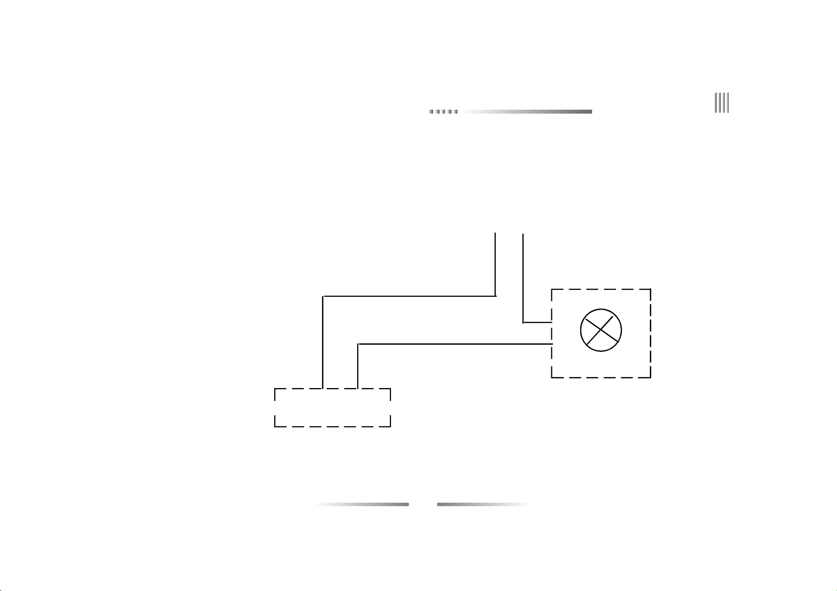
3.3.4 Alarm Input/Output Connection
Alarm input: Input resistance : 22K Ω
Sensor power: The machine provides a +12V DC power outp ut port.
15
Page 16

User Manual
Alarm sensor connection:
Alarm input: The physical connections of the normal on/off mode are the s ame. And user can select normal on/off mode in the DVR. Typical alarm
connection: the sensor power supply is provided by DVR. The fig is as follows:
sensor
+
-
DVR NC C
+12V GND Alarm input 1 Alarm input 2
16
Page 17

If the distance between the probe and DVR is too far, the probe requires a separate power supp ly:
12V Power Supply
GND +12V
sensor
+
-
DVR NC C
+12V GND Alarm input 1 Alarm input 2
Net DVR
17
Page 18
User Manual
If we parallel connected the sensor, the DVR can not recognize the triggered sensor. User n eed to ha ve a resistance.
+12V GND Alarm input 1 Alarm input 2
sensor port
+ - C NC + - C NC + - C NC
sensor sensor sensor
18
Page 19
Net DVR
Alarm output connection:
The alarm output side is normal-off and do not have voltage output. The other alarm equipments need the individual power supply.
supply the power separately
Alarm
Output1A Output1B
DVR
Normally, Alarm’s power usually is much bigger, preferab ly supply power separately, and do not use the DVR's power to supply.
Each series alarm output critical parameters are as follows: 120V/AC1A,24V/DC1A.Exceeding these parameters will damage the motherboard.
19
Page 20

User Manual
3.3.5 RS-485 Connection
Attentions for PTZ decoder connection:
1. Confirm that the PTZ decoder and Net DVR are one point ground connected, or common mode voltage m ight exist to cause the PTZ invalid.
2. Prevent high voltag e inroad, carefully dis pose connection cables secure thunder proof.
RS485:For PTZ control, series keyboard and transparency port connection.
3.3.6 Keyboard Controlling
If you want to unify control more tha n one DVR, you have to use the series keyboard (we suggest user using one series keyboard to control
more than one DVR in the same model). The function of the keyboard is the same with the remote contr oller (Note: the keyboard mu st be added
with the protocol from our company and go through the test of our company). Take the RS485 i nterface series keyboard for example:
1. In the DVR menu: “COM Setup”, to the corres ponding device type to the seria l keyboard,then setup the protocol,baud rate,addres s code.
2. Connect with the power supplier.
3. Connect between RS485+ of the keyboard and RS485+ of the DVR, also RS485- of
the keyboard and RS485- of the DVR.
4. Shift keyboard mode to DVR mode, input corres ponding address code, then you can
control DVRs.
The detail set of keyboard can refer to the user ma nua l of keyboard.
3.3.7 Intercommunication Port
There is a voice input port on the back panel, which is used to connect the extral power microphone.
3.3.8 Front panel decription
20
Page 21
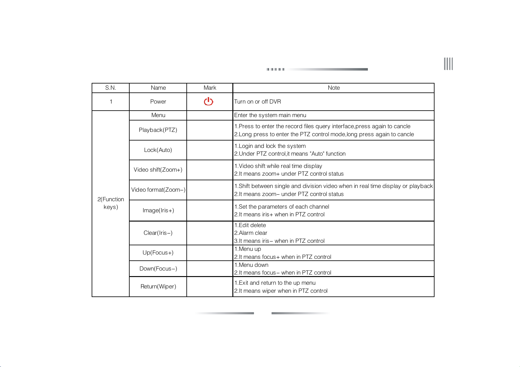
S.N. Name Mark Note
1 Power Turn on or off DVR
Menu Enter the system main menu
Net DVR
2(Function
keys)
Playback(PTZ)
Lock(Auto)
Video shift(Zoom+)
Video format(Zoom-)
Image(Iris+)
Clear(Iris-)
Up(Focus+)
Down(Focus-)
Return(Wiper)
1.Press to enter the record files query interface,press again to cancle
2.Long press to enter the PTZ control mode,long press again to cancle
1.Login and lock the system
2.Under PTZ control,it means "Auto" function
1.Video shift while real time display
2.It means zoom+ under PTZ control status
1.Shift between single and division video when in real time display or playback
2.It means zoom- under PTZ control status
1.Set the parameters of each channel
2.It means iris+ when in PTZ control
1.Edit delete
2.Alarm clear
3.It means iris- when in PTZ control
1.Menu up
2.It means focus+ when in PTZ control
1.Menu down
2.It means focus- when in PTZ control
1.Exit and return to the up menu
2.It means wiper when in PTZ control
21
Page 22
User Manual
POWER
HDD
3(Indication
lamp area)
4(Direction
keys)
IR
ALARM Alarm indication lamp,it is light when there is alarm,or it will be off
REC Record indication lamp,it is blink when DVR is recording,or it will be off
NET
Slow play 1.Cursor move;2.Slow play;3.It means up while in PTZ control
Frame on 1.Cursor move;2.Frame on;3.It means down while in PTZ control
Rewind 1.Cursor move;2.Rewind;3.It means left while in PTZ control
Fast forward 1.Cursor move;2.Fast forward;3.It means right while in PTZ control
While supplying power to DVR and the system running,this lamp will be
lighted to green.When the system is in standby mode,this lamp will be
lighted to red.When power supply cut off,the lamp will be off
Hard disk indication,it is blink when the hard disk is working,or it will be
off
Infrared signal receiver lamp,when operate the DVR by remote
control,it will blink
Network connection indication lamp,it is light when the PC client
connect to the DVR
OK/Play/Pause ← 1.Confirm select;2.Play/Pause
22
Page 23

Net DVR
3.4 Mouse Operation
Besid es remote controller, mous e also can be used to control the DVR. System also su pports mouse hot plug.
Right click the mouse:
1. If the system is in login status, right click the mouse,then shortcut menu will display.
2. If DVR is locked and in real time monitor status, the login menu will pop out when right click the mouse. The
system default setting user name is “admin”, and password is 888888(double click left button to open the flexible
keyboard).
3. Once entering the menu, right click the mouse, it will let you exit the current interface and back to the former
menu or exit the main menu.
4. For date input, left click the mouse you can see the software keyboard. After input date, right click the mouse you
can exit the software keyboard.
Left click the mouse:
1. Left click the mous e, and you will enter the functional menu.
2. In the main menu, left click and choose the item to enter or set up the parameters.
3. When sel ecting the motion detection setup, left click the mouse to change the st atus of the mot ion detection square unit.
4. To set up the video images parameters, you can change the brightness, contrast, saturation, hue of the image by left click the mouse on a
certain point you prefer.
5. Left click mouse in the input box and choose number, uppercase/lowercase letter, symbol, delete, blank, confirm button in the software keyboard
to input target informa tion.(Through click the Caps button ,you can switch the s tatus between uppercase and lowercas e )
23
Page 24

User Manual
Double click left mouse: the division can be switched by double click. Double click left mouse in the input box to enable the software keyboard , right
click the mouse to exit software keyboard. The interface is as follows:
24
Page 25

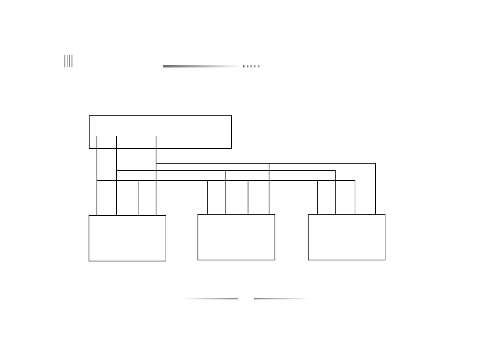
3.5 Menu Operation Description
3.5.1 Menu Structure Chart
Net DVR
25
Page 26

User Manual
3.5.2 Menu Option Schedule
Menu Instruction
1.Display contrast:from 1:1 to 1:5,the color of background is changed from
light to da rk.
General
setup
Record
setup
General
setup
Time setup Set system date,time.
Schedule
record
Record
parameters
2.Video format(PAL,NTSC).
3.Record overwrite mode(auto,alarm indicate);
4.Auto lock setup:1 -10 minutes.
5.Resolution:800 X 600,1024X76 81280X1024,1440X900,1920X1080,1080P,
6. Language switching: Support in both Chinese and English switching
Set continuous record time table.
1.Record type: manual, schedule, motion detection and alarm record.
2.Definition:CIF;
3.Bitrate type:CBR,VBR;
4.Bit rate size:100K,128K,256K,512K,1M;(Under the CIF maximizing th e
1M)
5.Image quality:6 level(highest, higher, high, middle, low, lowest)
26
Page 27

Net DVR
Record
setup
Output
setup
Record
parameters
Display
Setup
Sequence
Setup
Video Matrix Video matrix se tup,support 1:1 or 1:N output.
6.Video frame rate :PAL 2-25F/S optional;NTSC 2-30 F/S optional.
7.Audio.
8.Network HD, bitrate, quality, audio(c orrespo nding to su b stream).
1.Setting channel name.
2.Video mask area.
3.Channel duplication.
4.Date format setu p:year-month-da y,month-day-year.
5.OSD setup:channel name,time,week,temperature.
6.Video parameters setup:brightness,transparence,contrast,Hue.
7.Video input adjustment.
Sequ ence setup:Sequence cruise channels,polling interval,sequence
cruise type.
27
Page 28

User Manual
1.Alarm schedule.
Alarm setup
Motion
Detection
Sensor
Detection
Alarm
Output
Email Setup Support ema il alarm uplo ad.
2.Motion detect sensitivity:1-5 level(5 is the highest).
3.Set m otion detection a rea.
4.Video lost alarm.
5.Channel duplication.
1.Sensor ID.
2.Alarm schedule.
3.Relat e the recording channel.
4.Recall PTZ preset position.
5.Channel duplication.
1.Full screen when alarm output.
2.Buzzer alarm output.
3.Alarm retain time(2- 300 s).
4.Alarm type:n ormal on/off.
5.Alarm recording time.
6.Alarm output duplicatio n.
28
Page 29

Net DVR
Network Setup
COM Setup
System
Management
IP Setup
Setting server name,DNS server,IP address,network transport ports,LAN
multicast
PPPOE Setting dial-up username and password, for PPPOE dial-up
DDNS Choose DDNS server
Keyboard address,series type,COM device,baudrate,date bit,stop bit,parity
COM Setup
bit
PTZ Setup PTZ protocol,speed,address code
1.Add and delete user account.
2.Change local/remote user account and authority.Support remote user
User
authorities: remote preview,parameter setup,remote playback,remote
Management
backup,log Inquiry,voice talk,remote upgrade,user binding IP and MAC
address.
Backup Setup Support backup, require, playback the record date.
Hard Disk
Display the status, information of each HDD,HDD format.
Management
Restore to default setting: display setup, record parameter, manual, motion,
Restore to
schedule, alarm record, PTZ setup, network setup, COM setup,Channel
Default
setup, password setup, video parameters, alarm output, matrix setup
29
Page 30

User Manual
Syete m
Inform ation
Menu of
Right Click
the Mouse
Syete m
Inform ation
Recording
Status
Alarm Stat us Display the alarm status of each chan nel(sensor alarm,motion alarm,lost alarm)
Online Stat us Display the username, IP address, c onne cted channel
Log Inf ormation Require system log, display number of log
Main Menu Ent er the mai n me nu rapidly
Image Switch Swi tch the channel rapidly
Video Zoom Ent er the real time digital zoom men u rapidly
PTZ Ent er the PTZ m enu rapidly
Alarm Clear Alarm Clear
Video
Parameters
Logout Logout
Shutdown Shu tdown (user should press the power in front panel next time in this case
Display software version, m ain board serial No.,SCM version, IP address, MAC
address, file system , video sta ndard and language
Display the recording status o f each cha nnel
Video parameter adjustment(brightness, cont rast, satura tion, Hue )
Mute Mute
Restart Restart the local DVR
30
Page 31

Net DVR
Chapter 4 Device Operation
4.1 Power On/off and Login /Lock
Power on: After connected up the power cable, the front panel of the DVR will s tart and enter the s t andby state. Click the “power” button on the
remote controller for 3 seconds to enter the running state.
Power off: When the system is under the running state, click “power” button on the remote controller to popup the shut down interface. And clicked
the “confirm” button, the system will enter the st andby state.
Login/Lock :To avoid unauthorized user using the machine or influencing the system’s normal working, w e speciall y set the key lock a nd unlock
function for the machine.
4.1.1 Keystroke Unlock/Lock
When multi DVRs are put to work together, using the remote controller may influence the machin es which users do not intend to control. So we
set system key lock fun ction correspond to remote control. Under the system management of DVR main m enu, please enter series configuration and
setup device number, then enable key lock and save it. Now to press the DN button on the remote cont roller, the DVR is locked, and you will see the
"LOCK" light on the front panel is on.To unlock the DVR ,please press the DN button and input the c orrespondi ng DVR device num ber(Device
number range is 1-99,default set is 1).
Note: If the remote control does not respond, please check if this function is enabled.
31
Page 32

User Manual
4.1.2 System Login
When the system is in the status of locking “ ”, press the “Login/Lock” on the remote controller or right click the mouse, the figure of login
will appear as follows:
Input user name and password on the login port(distribute in authority in a dvance), after you in put correct user name and passw ord and press
“ENTER”, the sign “ ” on the lower left corner will switch to “ ” automatically, and show the current user name. Then you can carry on the
operations in the authority to the system at the moment.
1.Default user:admin,default password:888888.
2.When you inpu t the incorrect password 3 times continuously,the system will
alarm and get into the status of locking automatically. In that case ,you need to
click th e “clear” on remote controller to retype the password.
3.To input name and password, you can left click mouse .It will pop out software
keyboard. Right click mouse to exit.
Note: For the sake of safety, please change the default password immediately.
4.1.3 System Lock
When the system is in login status, according to the automatic locking time setting in the “general setting”(System default automatic lock time
is 3 minutes),if there is no operation in the automatic locking time,the system will automatically logout. You can also press “login/lock” on the remote
controller or right click mouse to logout.
4.1.4 Main Menu
After user log in successfully, and click the “MENU” on the remote controller , the system will switch to main menu.
32
Page 33

Net DVR
4.2 General Setup
4.2.1 General Setup
Overwrite
We suggest that user select auto overwrite mode, when disk is full, the DVR will auto overwrite the earliest recording file. The alarm indicate method:
When HDD is full, GUI information indicates whether overwrite the earliest recording files, and stop the recording.
Auto locking
When you enable auto locking, system will enter the status of locking in fixed time(1~10 min). For example, if you set the locking time to 3 minutes,
during this period if there is no operation, the system will auto lock.
Video format
User can choose the systerm video format as PAL or NTSC.
Resolution
Su pport 800*600,1024*768,1280*1024,1440*90 0, 1920*108 0,
1080Padjustment.
Display contrast
When you enable this option, you can setup the menu display contras t.
There are 5 levels and the default value is 5:1. When “1” is chosen, the
background color is the lightest.
33
Page 34

User Manual
4.2.2 Time Setup
Time setup
After login, user can through “general setup”-> “time setup” to enter the time setup interface. The fig is as follows:
This function is used to set or modify current system time, the system adopted the perpetual calenda r, the day will change as the date’s change.
(Note: please check the system time when firstly use. Because system time is in close relation with video record, try not to adjust system time on
general occasion)
Network time checking
NTP:NTP(N etw ork Time Protocol) means regulate the time form remote
server via network .
The default sever is hk.pool.ntp.org, port: 123,time zone is GMT+08 :00.
Make sure select “NTP” before use this function.
1.The system support 26 time zone for setting, user can set according to
current zone.
2.We do not suggest user change the Time server on g eneral occas ion. If
connect fai led, you can manually select the other server.
3.Port and time zone is optional.
4.The s ystem will automatically regulate time by update interval which
selected by user.
5.DVR need to access internet to realize NTP.
34
Page 35

Net DVR
4.3 Record Setup
4.3.1 Record Parameter
Before using the record function, it is important to setting the record parameter. It is related to video playback and hard disk capacity, etc. After
login, select “record setup”-> “record parameter”,enter the interface as follows:
Channel No.:Customer can select the cha nnel by pressing “ +”, “-” on remote controller or by the mouse.
Record mode:The record parameters will be active in the selected record mode.
Definition: CIF/D1 adjustable.
Encoding stream type: VBR and CBR.
VBR: It means when compress the video signal, system can adjust the
compression bite rate dynamically according to the ch anging of the
image source.Thus , when recording, system maximally saves HDD
capa city, and for net transmission, the bandwidth is also maximally
utilized.
CBR: The compression bitra te keep s constant even w hen image source
changes. The characteristic for CBR is in limited bitrate to have g ood
compression images, as well as easy to estimate the HDD occupation
and network bandwidth.
35
Page 36

User Manual
Encoding strea m: When compressing the intense moving image, we should make a u pper limit of the compress ion bitrate, there are (unit: bps):
100K,128K,256K,512K,1M(Under the CIF maximizing the 1M.Note: the more intense of the movement, the h igher b ite rate you should set).
Video quality:There are 6 levels of video quality(highest, higher, high, middle, low, lowest).
Au dio:The on/off switch for audio(Tick off indicates open, otherwise means off).
Dual streams
1.The parameters of local stream are for main stream. The local stream parameter settings affect the recording main stream and network main stream.
2.The parameters of net s tream are for sub stream. The net stream pa rameter setting affect n etwork s ub stream.
Pre-record time: The 4 record modes support Pre-record function, default pre-record time is 1 0s, ran ge is 0-3 0s. Due to the variable bitrate, the
actual pre-record time may have some difference with what your set.
Delay record time :The record duration time when the motion/s ensor ala rm appears, default duration t ime is 30s,range is 0-180s.
4.3.2 Manual Record
After login, click the “Manual” on the low er left corner,or press the
“Record” button on the remote controller to enter the manual record interface,
the figure is as follows:
When the channel button t urns yellow,the ma nual record is started,
otherw ise the button is grey.Once the manual recording is started, it will not
stop recording until manual closing.If the power is off abnormally, the recording
will continue after the power is on.
36
Page 37

Net DVR
4.3.3 Schedule Record
To enter the schedule recording interface,follow the steps below:
1.Select the corresponding channel No..
2.Select the recordin g date(everyday or someday),and set the record deployment period.
3.Set the alarm deployment period ,system supports setting multi-periods. Time period should be selected in chronological order. Tick off the date and
then enable the time period. By dragging the left mouse to set the deployment period .
(Note: double click left mouse can cancel one selected time period.)
4.Click “save” to activa te the settings, you can als o duplicate the settings to other channels.
37
Page 38

User Manual
4.4 Output Setup
4.4.1 Display setting
After login,click “ma in menu”-> “output setup”-> “display setup”, enter the interface as follows:
It’s used for adjusting the channel parameters, include chann el name, video mask, video adjustment, channel name position and OSD setting.
1.Channel Name
The channel name can be established at most 16 Chinese characters or 32
English letter and numeral.
Modify by mouse:Double click left but to n to pop out the soft ware
keyboard; In the pinyin input states, click “En” to switch to English input
meth od.
Modify by remote controller:Use "#" to switch the input method.
Channel name fi xed fold on the top left corner of the corresponding
channel, you can en ter th e channel name position interface, and s elect the
channel name to ad just its position by dragging the mouse .
When copy the channel settings, not include copying the channel na me.
2.Mask Area Setting
In some s urveillance occasion, user need to mask the sensitivity or private
area in the s urveillance area of the location, such as ATM’s password area.
Each channel can max support 4 mask areas. The way of set the mask area is as follows:
Tick off the video mask to enable this function, click “mask area”to enter the video mask status.
Set by mouse:Left click a pane as the start position of the mask area, then click another pa ne as the end position, and the area will shown.
38
Page 39

Net DVR
Set by remote controller : press direction key to move the cursor, press “OK” to confirm the start p osition, then move the cursor to select the area
you want to ma sk, press “OK” again to confirm the end position. Press “clear” to cancel the area.
Back to the channel setting interfa ce, cl ick save to activate the setting.
The selected mask area will take effect both in the real-time and the record.
3.Video adjustment
After login,u ser can “display setup”-> “Video Para” or right click mouse and press “image”
button remote controller instead, then select the “ Video Para” to enter the interface.
Default video parameter: brightness(128), contrast(128), saturation(128), hue(128).
Channel No.: used to switch channels,user can also setup all channels directly.
Adjustment Method:
(1) Select the parameters you want to change, then press “+” “-” button on the remote controller.
(2) Click the left mouse on the “+” “-” to change the value , the “+” “-” on the interface can
indicate the increase or decrease of the value.
(3) Video input adjustment
Video input adjustment: adjust black edges on each channel. The input video is normally
with black edges, actually DVR reduced black edges by moving the capturing window position
to capture more effective informa tion.
Horizontal offset: set the capturing window potion.
Vertica l offset: fixed.
4.4.2 Preview Digital Zoom
Setup method:after login, right click the channel to enlarge to full screen,then click mouse w heel to start setting, left click to select start point, then
move to the end poin t and click a gain. Dra g any border to enlarge the selected area. Double left cli ck the mouse to cancel the selection, right click
39
Page 40

User Manual
the mouse to exit the digital zoom.
4.4.3 Sequence Cruise
This function is used to cruise different channels, user can select sequence channel No.,sequence division,sequence interval time. The interface is
as follows:
Sequence format:1ch,4ch,9ch,16ch division s.
Sequence channel number: user can set the sequence channel number, the sequence channel number must be more than the selected division.
Sequence interval time: range is 3-60s.
Note: The sequence function is only enable in system locking status.
40
Page 41

Net DVR
4.5 Alarm Setup
4.5.1 Motion Detection
1.After login, click “main menu”-> “alarm setup”,the interface is as follows:
By analyzing the real-time video, the system could confirm whether the video scene has changed or not. If you need record when the video scene
is changed, then you can through “Motion Detection” to perform it, user could set the motion detection time, schedule time, sensitivity, detection area,
alarm output channel and whether ena ble audio alarm.The specific operation steps of motion detection setup is as follows:
(1) After login, through “main menu”-> “record setup”-> “record parameter” to set the corresponding channel p re-record time and delay record
ti me.
(2) Choose the motion record channel.
(3) Set the schedule time(the specific setting please refer to schedule record).
(4) Select the sensitivity:The sensitivity of the motion detection is adjustable a nd the sensitivity g oes up in order from 1 to 5.When the motion
detection of the current channel happens, the system will alarm and record. If the sensitivity is low, such as “1”,when the video scene make a big change,
the system will motion detection alarm; If the sensitivity is high, such as “5”,when the video scene make little change, the system will motion detection
alarm.
(5) Settin g detection area:
Before you start the motion detect, you should define which areas are detection areas, then when ima ge is changed in these areas, it will detect and make
alarm. System default yellow area is detection area.
Setting detection area by remote controller.Press direction button, move the cursor to set the start point,then move cursor to the area you want to be
the end point. Press the confirm button to finish the operation. Left cli ck the mouse to change the status of the motion detection square unit. Then
press “return” button to the record setup status ,click “save” to activate the setup.
41
Page 42

User Manual
Setting detection area by mouse: Left click a pane as the start position of the detection area, then click another pane as the end position, and the area
will shown. Double left click mouse to cancel your choice. Click “return” to record setup interface, click “sa ve” to save the setup.
(6) Alarm output setup: The button will turn yellow when enable the alarm output function ,otherwise the button is grey.
2.Video Lost Alarm
The DVR default enable alarm output when video lost. We provide three ways to output alarm: aud io, buzzer, full screen.You can press “information”
button to en ter alarm information statu s rapidly.
4.5.2 Sensor Alarm Setup
The steps of sensor alarm setup is as follows:
(1) After login, choose “main menu”-> “Record setup”-> “record parameter” to enter the setting interface of alarm record, set the corresponding
channel, pre-record time and delay record time.
(2) Choose “main menu”-> “alarm setup”-> “sensor”, enter the interface of alarm record, the interface is as follows:
42
Page 43

Net DVR
(3) Choose the sensor type.
(4) Choose the sensor number.
(5) Set the deployment period (the specific setting please refer to schedule record),left click mouse to set start point then drag mouse to the end point.
(6) The linkage record channel can record when alarming, we recommend that each channel correspond with each sensor, so that we can find the
alarm record files by channel, t he yellow channel button means have linkage alarm record, gray means not linkage to any alarm record.
(7) Alarm output setup: you can select the alarm output button. (Yellow indicates enable, and grey indicates disable).
The system support recall to preset point function when alarm appear(the precondition is the camera support preset function),the setting procedure
is as follows:
1.Click “PTZ preset point” to enter the PTZ pres et interface, then you
can set the preset point.(Note: the range of the PTZ preset is 1-255,2 55
means close, when copying the channel parameters, these settings will not
copied to other channels). After finishing this operation, you should right
click mouse to enter the up menu and click “save” to activate the setting.
2.In “COM Setup” interface you can set COM type, COM device, baudrate.
In the PTZ setup interface you can set the protocol, address code.
3.Switch to the channel which you want to set preset points, press the
“PTZ” button on remote controller to enter the PTZ control mode, then
press “PRESET”, input the preset number mentioned in step 1,or you can
right click the mouse to enter the PTZ status, select “PTZ”, then you can
see the interface, input the preset number mentioned in step 1 to the box,
click “preset” to save setting. Right click the mouse again to quit.
43
Page 44

User Manual
4.5.3 Alarm Output
After login,through “Alarm setup”-> “Alarm output” continuous opera tions to enter A larm output interface.The interface is as follows:
The “Alarm output” interface have the following options: Sensor type, Alarm to full-screen,Ala rm to Buzzer,Audio Alarm,Alarm output Time,
Alarm output deployment time.
Sensor type: n ormal on/off.
Alarm to full-screen: when the system is in multi-picture and the alarm is triggered, the alarm chan nel will auto full-screen.
Alarm to buzzer: when the alarm is triggered,the system will start buzzing.
Audio alarm: when the alarm is triggered, the alarm sound will output to
the audio output.
Alarm ou tput time: inspection(2~300s),the system default is 30s.
Alarm deployment time: the system default alarm output schedule time
is 00: 00-23:59 of everyday.
44
Page 45

Net DVR
4.5.4 Email Setup
After login, click “main menu”-> “alarm setup”-> “email setup” ,the interface is as follows:
Email setup steps:
(1) Enable the Email upload, select the related email. W hen alarm(video lost, motion detect, sensor detect) triggered, the DVR will send email to
user mail account automatically.
(2) Set the SMTP server, default is s mtp.126.com.
(3) Input the username and password of the mail account.
(4) Input the mail address which applied from SMTP server in the “sender email”.
(5) Input the receiver mail box which can be multiple and separated by
“;”, the maximum length of the letter you input is 256 bit.
(6) Default port is 25,nomally do not need to change.
(7) Set the e-mail upload interval time, that is the time interval for
upload ala rm information to the target email, no matter how many times
alarm triggered, it just upload once during every interval time, and also can
be uploaded a snapshot which is .jpg in default.
(8) Aft er saved the settin g, the receiver mai lbox wil l get the alarm
information m ail when alarm is triggered.
Note: If mail unable to send, please check whether DVR can access internet,
or the mail server can work well.
45
Page 46

User Manual
4.6 COM Setup
After login, click “Main Menu”-> “COM setup” ,the interface is as follows:
You can do the operation of connecting other serial device to DVR in this interface.DVR provide two pairs of serial connection terminal:RS4 85
and RX.The two serial port both are full duplex terminal which have receive and transmit function. D VR can be connected to PTZ, serial keyboard
and other serial devices at the same time.
4.6.1 COM
“COM”’s interface is as follows:
The parameters of RS485 include:baudrate, data bit, stop bit,check bit etc.
These parameters are used for defining the COM type, there are 3
types to choos e: PTZ, serial keyboard, transpa rency channel.
Baudrate:Set the baudrate of the communica tion between COM and
its outer devices.Such as PTZ ,keyboard's baudrate must be identical with
DVR system's baudrate.
Data bit,stop bit,check bit: Set the data bit, stop bit and check bit
according to the PTZ protocol code. Commonl y, the PTZ protocol’s
default date bit is 8,check bit is None, stop bit is 1.
Host a ddress: When one keyboard connect with several DVRs in the
parallel way,the keyboard is used to control and differentiate different
DVR’s identify code.
PTZ protocol: Set the outer PTZ protocol in this option, an d the
protocol must be the same with the PTZ itself.
46
Page 47

Net DVR
4.6.2 PTZ
The procedure of PTZ setting:
Set COM type, COM device and baudrate in the “COM setup” interface.
Enter the “PTZ Setup” interface to set protocol and ad dress code (The default PTZ address code is coincide with every channel, for instance, the
first channel’s PTZ address code is 1).
Note: PTZ protocol, baudrate, address code must coincide with the PTZ camera itself.
Switch the channel to single picture display status, press the “PTZ” key on the remote controller to get in the PTZ control mode, then you can use
the remote controller to control the PTZ, press “PTZ” again you can quit the PTZ control mode; You can als o right click the mouse to enter the PTZ
control interface.
Setting and calling preset point by th e remote controller :
Enter the PTZ status, press the direction button make the PTZ turn the
direction which you want to set as p reset point,press “*preset” botton
on remote controller and input the No. of the preset point in the box(such
as 001),then turn the PTZ to another direction,if you press the
“#call” button and input the No. (1) which you preset to the box,the
PTZ w ill turn to the 0 01 preset point automa tically.
Setting and calling preset point by mouse: Enter the PTZ status, double
left click mouse at the preset input box to enabl e the software-keyboard
and input the preset No.(such as 1).Right click mouse to quit softwa re-
keyboard, then click “preset” to activate the s etup. Then turn the PTZ to
another direction,if you click the “call” and input the No.(1) which you
preset to the box,the PTZ will turn to the 1 preset point automatically.
Click “ return” to quit the PTZ interface.
47
Page 48

User Manual
Multi-preset position sequence (Note: Only enable when system log off)
(1) Sequence interval time:0-99s.
(2) Preset No.:each channel can max set 16 preset position.
(3) Range of preset No.:001-255,255 means closed.
4.7 Network Setup
After login, user can through “Main menu”-> “Network Setup” to
enter the network setup interface.
4.7.1 IP Setup
The Network setup interface is as follows:
Auto acquire IP address:If the server in the LAN where the DVR is placed
has the DHCP service and you have selected the “DHCP” option, DVR will
obtain a dynamic IP address from the server an d displayed within the IP
address column.
Di sable DHCP: If there is no DHCP service in the LAN, you can choose this option to designate the static IP address.
IP set tings: This IP must be unique. It can’t conflict with the IP of other servers or working stations in the same LAN.Default: 192.168.0.6.
Subnet mask code: Used to differentiate subnet.
Gateway address:Used to realize communication between different networks, it needs to set up ga teway address.
DNS server:Input the DNS address acquired by PPPOE(Note: Please ensure the DNS address is correct, otherwise the DDNS will not work).
Command port: The port for data transmitting with client, default set is 8101,port range 8000-9000.
HTTP port:IE browse port, d efault set is 81. Port can be changed. You have to restart the system to effect the changes. After you change the
48
Page 49

Net DVR
HTTP p ort, you should type http://IP:port for IE browse.
Enable multicast: This function only affects UDP stream.
Multiple IP address:Multiple IP address set range is from 224.0.0.0 to 239.255.255.255;The system default is 239.0.0.1.
Multiple port:The default port is start with 8000.Note: If there are 2 DVRs or above in one section of the n et, please ensure that the multiple port
is unique, or you cannot open the multiple video.
It shows the network information of the public network after the ADSL connection succeeds(Such as IP address and Subnet mask code). Click the “save”
key to save the information. Next time, it will be dial to net automatically( Note: You must connect the net manually after first set the “auto re-dial”).
4.7.2 DDNS
Our DVR system support DDNS function. You can analyze the WAN
IP which is directly dial form the ADSL, and also the router ma pping
WAN IP address.This function supports the domain name which is registered
from www.oray.cn, www.dyndns.com. You can choose one of them according
to the need.
Login www.oray.cn to apply the oray DDNS service, please write down
the username and the password.Choose the oray server on the DVR,
input the username, password you have applied, save it, then you can see
the DDNS information after a few minutes.
Login www.dyndns.com to apply the dyndns DDNS service, please
write down the username and the password.Choose the dyndns server on
the DVR,input the username, password you have applied, save it, then you
can see the DDNS information after a few minutes.
49
Page 50

User Manual
4.7.3 PPPOE
Select “Network Setup” and click “PPPOE”, and the interface is as follows:
PPPOE is one of the mode to connect to the WAN: C onnect to the WAN by system via dialing the ADSL directly.
Username:ADSL account user name.
Password:ADSL account password.
Con nect:After you input the correct ADSL account and password,focus the cursor on the icon and pres s “Connect” to connect the WAN.
A uto Connect: If you select this option, system w ill automatically connect the WAN after disconnect ion.
Save password: If you select this option, system will automatically
save the ADSL password, so you don't need to input them again when
reconn ect to the WAN.
It s hows the network information of the public network(such as IP,
Subnet address) after the connection succeeds. Press “save” button, it will
save the options include auto re-dial and save password.
Note: You must connect the net manually after first set the “auto re-dial”.
50
Page 51

Net DVR
4.8 Playback
System has two ways to enter playback interface:
(1) Enter the playback interface by press “play” button on the remote controller . Click yellow magnifier icon to start the accurate time playback,press
“playback” again you can switch to the record file inquiry interface.
(2) After login, click “main menu”-> “playback” to enter the playback interface as follows:
Click the blue zoom key to enter the record inquire interface, you can
choose record files by period or record type. Click yellow zoom mark to
switch to the accurate playback interface.
There are 4 types record file: manual, schedule, motion, alarm. You can
press “+” or “-” button on the remote controller or left click mouse to
choose file type. System default list all record types files.
Full channel playback:System support multi-playback (8channels)
function.They are all real time playback. You can press the number button
on remote controller to switch to another channel when playback the
record.
After choos e time period and channel, system will update the record
data.
When you choose a record file, the start/s top time and size of the file
will display at the lower part of the interface.
Move cursor to the file you want by remote controller, press “confirm” button to sta rt playback the file.you can also use this function by double
left click mouse on the file.
Click page up/down key for category search in different pages.
51
Page 52

User Manual
Right click the mouse during playback to use/hide playback control menu.
Support digital zoom when playback by mouse. Operation procedure: Enter the playback image, click mouse wheel to start option,left click mouse
for selecting digital zoom start point, then drag mouse to the point where you want to be digital zo om end point. There will be appear an square. Drag
any border of the square area to zoom in. Right click mouse to quit the digital zoom interface.
4.9 System Management
After login, user can through “Main Menu”-> “System Management”
enter the s ystem management interface. The figure is as follow:
4.9.1 User Management
When the DVR leaves the factory, there is just one user named “admin”,
the default password is 888888,please use this password when firstly login
the DVR. User “admin” has the most powerful right of all the users, and can
create15 users at most, all the rights of the 15 users are distributed by
“admin”. In order to protect the DVR’s security, the administrator should
modi fy the password on the “User mana gement” interface.
1. User management
Add/delete user:Focus the cursor on the “add” icon and click to add new user, move the cursor to select the user in the user list, then focus the cursor
on the “delete” icon and click to delete the user.
52
Page 53

Net DVR
Modify password:Using the direction key of the remote controller to move the cursor to the user list, press “OK”, then you can get in the interface,
or double click the mouse to get in.
Support local and remote rights setting.
Display the user list when login: When login the DVR, use the “+”, “-” on the remote controller or click the wheel of the mouse to select the user;
If not select “Display the user list when login” , you must input the username when login.
2. User Group
Support user group function:each user can just take part in one group,the admin user can distrib ute rights to users in this group.The interface is as
follows.
53
Page 54

User Manual
4.9.2 Backup Management
There are three ways for back up:(1) Backup the file to remote computer through network. For detail operation please refer to the DVR client user
manual. (2) U disk backup,suppot U disk hot-swappable:The backup disk must be FAT32 and capacity is bigger than 512M.
1.File Backup
The backup interface is the right figure above:
Backup function allows to backup up to 26 record files for different channels or different time periods. The details of back up is a s follows:
(1) Input time period and channel number.
54
Page 55

Net DVR
(2) Move the cursor to “ADD” and press to confirm. The ad ded file will appear in th e backup files lis t. For more record files, please select the time
period and channel number and add them to the list.
(3) After you add all the files, move the cursor to “BACKUP” icon and press to confirm, then system would automatically start to backup.
(4) You can backup a ny record files without waiting.
Backup files list: Display added record files for different channels and different time periods.
Backup host: User can name the host to differ it from other hosts. After setti ng up the host name, user can click “save” to confirm it.(Note: The host
name can be set up to maximum 32 characters.)
2.Backup file playback
To playback the backu p files, user has to enter the backup interface and click “Inquire” button,select the record file and press “ENTER” to playback.
Backup date: Display the backup files in current HDD backup partition.
Move the cursor on the date icon and pres s “ENTER ”, and the file list at
the right side would display all files information of the date.
Backup file li st: Display backup file information of a certain date.
Note: User can not use the fast forward function when display backup file.
4.9.3 Disk Management
After lo gin ,en ter the inte rface th rough “ Main Me nu” -> “D isk
Man agem ent” ,the interface is as follows:
The 1st line displays the connective HDD NO.. The 2nd line displays
the HDD status. The 3rd, 4th and 5th lines display the HDD capacity, free
spa ce and partition type informa tion. The last line displays the total HDD
capacity and total free s pace of a ll the HDDs.
55
Page 56

User Manual
Disk format: System supports only FAT32 format, the capacity of the HDD is ab ove 32G.System s upports only one partition for backup.
Format: Select the HDD NO., then focus on the “format” icon and press “OK” to choose the type of the p artition (DATA or BACKUP ). The
interface is as follows, after you confirmed the partiti on type, press “OK”, the system will prompt “It’s formatting...”.
4.9.4 Restore Default
The way to restore default setting: After login, through “System Management”-> “Default” conti nuous operations to enter the interface, the
interface is as follows:
Note: Network IP and port, System time, user account and hard disk management wouldn’t be restore default when do this operation.System
default parameters:
Common Para.:Contrast(5:1),Video format (PAL);Record overwrite mode(Auto cycle);Disk error alert(Ena bled);Open auto locking(Enabled),auto
lock time 3 minutes;Date format(YYYY-MM-DD);Display channel
name (Enabled);Display time(Enabled);Display temperature(Enabled);
Channel switch(Closed).
Rec. Para.:Record mode(All);Encoding stream type(VBR);Encoding
stream(512K);Record quality(High);Video frame(25);Audio(Enabled);
Transmission encoding stream(512K);Trans mis sion record quality(High);
Trans mission audio(enabled).
Record Mode:Manual(Closed);Schedule(Closed);Motion detection
(Closed);Alarm detection(Closed).
Network:Auto redia l(Closed);Auto login(Closed).
COM:Ba udrate(9600);Data bit(8);Parity bit(Non e);Stop bit(1);Keyboa rd
addres s(1);Protocol(Unknown).
Channel:Channel name(Reset to default);Video loss alarm(Enabled);
56
Page 57

Net DVR
Alarm output(1~2);Video area mask(No mask);Preset poll(Closed);Pre-record time(10s);Delay record time(30s).
4.9.5 Password Reset
When you forget the system password or the admin’s password, the factory’s default setting can be retrieved by t he following operati on.
The operations are as follows:
1.Shut off the machine and cut off the power supply.
2.Unload the cover screw, and remove the case lid from the machine.
3.Find J1, it's on top right of the SC M which is beset on the back of the front panel.
4.Jump the thread piece to put the legs 1, 2(next to the resistance R13) of J1 to the status of short circuit.(the thread piece is put on the legs 2, 3 when
leave fa ctory)
5.Connect the power supply, and start the machine. You can hear buzzer sounds, and it indicates that the passwords have been set to the default value
at the moment.
6.Shut off the machine again, and cut off the machine power supply.
7.Pull out the jumping thread piece, and let the legs 2, 3 of J1 to the s tatus of short circuit.
57
Page 58

User Manual
4.10 System Information
4.10.1 System Information
It displays software version, IP address etc. The interface is as follows:
4.10.2 Record Status
The interface is the right figure above:
Quick inquire the current system record status. It shows the record s tatus of each channel’s current record type, record quality,definition and
the audio record sta tus (on or off),if in the recording statu s, the “Type” bar would show the type of current record(manual,timer,motion, alarm),
record quality shows the current image quality.
58
Page 59

Net DVR
4.10.3 Alarm Status
The interface is as follows:
It shows the alrm type of each channel: Sensor alarm (Red color), motion alarm(Yellow color) and video lost alarm(Blue color). You can clear
the alarm th rough the “CLEAR” button of the remote controlleror click the “alarm clear” on the menu by mouse.
4.10.4 Online Status
It displays the information of outer PC which connected to DVR. Such as: IP address, login/off time.The interface is the right figure above:
59
Page 60

User Manual
4.10.5 Log Information
The interface is as follows:
At the bottom of log information interface will display page No., user can click page up/down to check (The number of the log item is no limited).
The log file can’t be recognized on PC,the log information of host side can search and show through client software.Click page up/down key for
category search in different pages.
Contents of the logbook:system start-up/shutdown and change version log, alarm log, PTZ control lo g, user login /log off, changing system
parameters, recording playback log, backup log, format HDD log , user login client log ,etc.
60
Page 61

Net DVR
4.11 Software Upgrade
There are 2 ways for firmware upgrade:1.Client software upgrade;2.USB device upgrade.Please read the statement carefully before upgrade.
4.11.1 Client Software Upgrade
Please double check the version of the upgra de software, so you can restore to the former version w hen your upgrade is failed. If your system are
running well or just don't need the new function, we recommend you keep the default version. Please backup the important record files before upgrade.
Do ensure supplying the power and the stability of network when upgrading. Network outages and inte rrupted power supply will cause upgrading
fail ure. On a PC client remote upgrade download files completed, the host-side did not a ppear “the update was s uccessful, which is resuming the
equipment, please be later...”,in six minutes, you ca n shut down and then reboot, then check whether the host computer update was successful.
Please double check the version of the upgrade software, including machine model and boot interface, and make sure whether it corresponds to your
system.If you have any doubts, don’t upgrade, or in case you fail to upgrad e the firmware, you can neither redo the s ystem upgrade nor restart the
machine(These upgrade failure machine must send back to the factory).
After upgrade, for the new features, please refer to the user manual of the new version. You can get the new version from our website or the suppliers.
Don’t modify the software(inclu ding the nam e of the firmware), otherwise, we will take no responsib ility and will not provide free update.
Make sure the client installation procedure is the same as the system.
The procedure is as follows:
1. Conn ect the Net DVR to PC by coherent network cable or LAN (pay attention to IP conflict).
2. Before upgrading, please confirm the IP address of host computer, then enter client end.
3. After login and choose “system” -> “Remote update”.
4. Choose “Browse”, choose the file to be updated, and refer to the following figure(left figure).
5. The following figure is displayed on DVR (right figure).
61
Page 62

User Manual
6. Waits for 3 seconds, the DVR will display “Transmitting data finished. Updating software ...”. It probably takes 2-3 minutes to update the software.
7. When a window that contains the information of upgrading successfully pops up, it means that the update finis hed. Then, the machine will
automatically restart.
8. After the system restart, the a dmin password is t he former version’s.
4.11.2 USB Upgrade
Operation steps:
1. Copy the upgrade.bin to the U disk.
2. Insert the USB flash to the USB port on the back panel, after th e USB device recognized, enter the "information" interface, click "USB
upgrade", and confirm the hints to start upgrade.
3. The host says “The system is updating...”.
4. When the upgrade have been finished, the host will pops out “Update success, it’s rebooting, please wait...”,that indicates the upgrade is
successful, then the host will restart automa tically.
62
Page 63

Net DVR
5. After the system restart, the a dmin password is t he former version's.
4.12 Power Resume
If the power is shut down unexpectedly when the system is in standby or working status, system could start automatically restart and resume to
the original s tatus after power back. The advantage of this function assures the system maintain the continuity condition for outage.
63
Page 64

User Manual
Appendix 1 IE Operation Instructions
Notice: Please set firewall rank for low or medium, and surf s oftware or net assistant software, etc. should be blocked or unloaded. Otherwise the
software may not run properly. Please guaran tee to install D irectX 9.0 of Microsoft and confirm the Internet Explorer edition is 6.0 version or
above.
1. LAN Configuration for IE Browse
1. “Ping”the hos t IP first to confirm i f the DVR is connected.
2. Type the host IP into windows IE and connect to the DVR. Input user name and password to log in. If the log in is succeeded, the following
interface will pop out.
64
Page 65

Net DVR
3. Please refer to “Client user guide” for further operation.
2. WAN Operation Instructions
If there is a fixed WAN IP address that can be allocated to the DVR host, the DVR host can directly access wide-area network, and can be visited after
set up IP, subnet mask and gateway.
The host-setting steps are as follows: after logging, click the “Menu” button, enter “Network Settin gs”, then choose and enter the “Dial-up Settings”
interface, input the user name and password, and click on the “Link” to make the DVR host access Internet by dial-up. After dial-up successfully, Net
DVR will display relevant information. User can input the host IP address in windows IE and visit th e host through network.
If you want to connect multiple DVRs to wide area network with only
one IP, please refer to the followin g instruction:
Firstly, set up IP, subnet mask and gateway in the “IP set up” interface
of “network setting” in the main menu of host DVR. Note: Gateway must be
set the same as the mapping router ’s LAN IP. After set-up, connect the
host to LAN to make the n etwork mapping on the dial-up internet router.
(Note: The instru ction is for TCP p rotocol mapping)
Through the router m apping:
Host network interface settings are as following:
Note: The values of command port and HTTP port indicated by red box
were 8101 and 81. Users ca n cu stomize the value of the two ports. After
setting and saving, DVR will res tart to take the setting into effect.
65
Fig 1
Page 66

User Manual
Take the TP-LINK as an example:
[1] After signing up routers, by choosing “Running Status” icon on left side menu
of Figure 2, view the LAN IP and WAN IP addres s of the routers, such as, the
LAN IP address 192.168.2.1, WAN IP address 11 6.30.143.163.
[2]Choose the “Transfer Rules” on Figu re 2 left menu, as shown in Figure 3,
respectively input “com man d port : 8101”, “HTTP monitor port: 81”, “IP
Address: 192.168.2.6”, as shown in Figure 1, and choose to enable the agreement
“ALL”. Click the “Save” to save the settings.
Fig 2 Fig 3
[3]Port Description: The command port is the TCP port of a ll DVRs communications, and HTTP port is I E browser port.
66
Page 67

Net DVR
a. When the two ports are default setting, directly input the WAN IP address (116.30.143.1 63) shown in Figure 2 into client manager, and sign in.
After login successfully, the interface is shown as Figure 4. For IE browse, directly input the WAN IP address (116.30.143.163) shown in Figure 2,
and input the correct user name and password, you can log in. After login successfully, the interfac e is shown as Figure 5.
Fig 4 Fig 5
b. when these two ports are not the default values, for IE browser, input as the following mode: http://116.30.143.163:http port. For client manager,
when login, input the command port in the login box.
Note: between IP address and port number, or between user name and port number, the pun ctuation “:” must be input.
67
Page 68

User Manual
Appendix 2: Net DVR Q&A
Thank you for choosing our DVR series products. We will always be at your services. In case you have any difficulty while using the products,
please refer to the below frequently asked questions & answers. If you cannot find solution here, or the solution offered here still fails, please feel free
to contact us by our hotlin e and/or technical support E-mail b ox. We will make most timely reply to your questions.
Testing Methods:
[1] Replace Method(Replace the power supply and HDD of the DVR).
[2] Minimum Load Method(Get rid of the HDD, video, audio an d alarm resource).
[3] Upgrade(Solve some incompatible problems).
Note:Some problems may be caus ed by incorrect operation. If you can not make sure the problems, plea se run “Reset default”option.
(A)The problem about rebooting, self testing, system halted.
01: Why the DVR doesn’t start up though power cable is well connected to power source?
01: 1. Check if you have turned on the switcher on the back panel. 2.Check if you have inputted the right power password and pressed Enter
button.
02: I see the Super DVR logo, but why it stops at self-check process?
02: To detect if the problem is caused by hard disks, please remove all the hard disks and start system again. The DVR can start up
without a hard disk. After start up, system will prompt “system does not detect the disk information , whether to continue”. Click “OK”
button, and t he host can engage in normal operation.
03: My system can finally start up but seems to be quite slow. Why?
03: Hard disk error will take system much time on rechecking.
68
Page 69

Net DVR
04: Why does my s ystem restart after self-check?
04: 1.Check the hard disks if they are in FAT32 file format, if not, change to FAT32. 2. Check Color System setting in Record Parameter
menu. In case this setting is PAL, while present video input is in NTSC format, which will cause system restart. 3. Please unplug the network
cable, to see w hether DVRs run normall y, since there are serious problems of the network which may a lso cause the host to restart
repeatedly.
05: Why my remoter doesn’t w ork?
05: 1.Please check if the IR indicator light on the front panel flashes when you make operations with the buttons. If not, please check whether
the remote control has run out of battery, or the remote control has been damaged. 2. Check if the front panel is in lock up status. If so, press
Login/Lock button and input power password to unlock. 3. Please check if the host software locks the operation. If yes, please input user
name, passw ord to login, so to make IR remoter control work.
06: Why system halts at some certain time?
06: In case system halts at some certain time, for example, around 7 :30am, please check your electri city system. This problem is mostly
happened in factories, when at around 7:30, all machines start and cause power supply in a short tem porarily. Try to make the DVR not
connect to the same circuit as the industrial machines.
(B)Display Problems
01: W hy there is nothing displayed on the monitor or the display keeps shaking?
01: 1.Check if the power is on or not. If the power is on, the power light at the front panel should be on. 2.Check the display mode. Refer
to VGA/CVBS display switch from the user manual.
02: Why my DVR display images that seems to be interfered, and like water wave shape?
02: 1.Please check if the video cable has well connected. 2. Check if there are strong electricity c urrent around the video cable. Please don’t
put video cable together with electricity cables to avoid interfering. 3.Please check if the DVR case is well grounded.
69
Page 70

User Manual
Only connect the case to ground by the screw on the back panel, while no other points connect to gro und. 4.Please check camera, monitor
and video cables if they are aging.
03: Why both the live display image and playback image are not showing the true color?
03: Please check if you have set the parameters well. (Plea se refer to chapter 4.2.1 for details)
04: Wh y my DVR displays distorted images on VGA monitor or cannot make full screen display?
04: 1.Please check if your VGA monitor is well set up. 2. Change your VGA monitor settings till make it full screen.
05: Why my DVR system shows disordered color?
05: 1.Please check you VGA data line, as well a s connection condition between DVR to VGA monitor. 2. Check if the DVR system has
overh eat.
06: I started my system s eemin g to be successfull, but there was a certain channel displaying nothing, neither caption. Why?
06: Please make restore to factory default settings.
07: Why it displays mosaics when playback?
07: 1.Check the recording parameter setting. If the recording parameter is set too low, it can influ ence the image quality and cause mosaics.
2.If bad sectors exist in the HDD, it might cause mosaics when playback. Users need to check HDD.
(C)Client manager and remote functions
01: Why my windows system refused my installing client manager software?
01: You may haven’t installed DirectX8.1 or above. Please make sure you have installed before instal lation.
70
Page 71

Net DVR
02: How to make remote surveillance?
02: 1.Install the client manager software, and connect the computer to the network, e.g. LAN, ADSL.2 . Set a fixed IP for the DVR:a.In LAN,
manually give the DVR a n IP, like 192.168.1.188.b.In Internet, you should apply for the fixed IP from Internet services sup pliers.3. Client
PC should also get an IP. If it’s in the same LAN as DVR, then set manually an IP like 192.168.1.23 for the PC.4. Test the connection between
client PC and DVR by PING the DVR IP address on the PC.5. Input DVR IP address and port number in th e client manager software, as well
as the user name and password that is preset on DVR.
03: When I connect to remote DVR, bu t I can get only picture with mosaics , and sometimes pictures are still. Why?
03: 1.Please check the network conditions. It’s probably blocked or very busy, so some video data ma y lose in transmission, which will cause
mosaics. 2. Check the DVR server side, if the original images have mos aics. 3. On win2003 operating system, after the successfully sign, if
DVR client cannot open image or images have mosaics, please set as the following: On the desktop spa ce, click the right button of mouse, and
select Attribute - > Settings - > High - > FAQ - > hardware acceleration option completely.
04: I h ave wel l connected the DVR with network cable (netw ork cable indicator light fla shes), but I fail to Ping the DVR from remote
computers. Why?
04: Please input “arp-d *” command on “Run Interfa ce of Computer” to delete items set by inet_ add r.
05: How to use client software to access DVR server?
05: A. Make sure whether the DVR server is turned on. B. Make sure the IP of DVR server is unique. C . Make sure the client software is installed
correctly on the client side. D. Use command ping to check whether the computer connected to DVR hos t. If not, Please input “arp-d*”
command to delete items set by inet_addr.
For example:
71
Page 72

User Manual
Following picture shows computer and 192.168.0.19 DVR connection has been established;Following pict ure shows computer and 192.168.0.
11 DVR connection has not been established:
E. Enter the client software. F. Input the IP, Port, user n ame, password of the DVR server, and then click login.
Note: If you still can not login successfully, please confirm the above user name and password or re peat checking A-> F steps. If you can not
login, please uninstall the client program, select new directory for installation, and then implement A-> F steps again.
06: I input DVR IP address, user name and password in client manager software, and system shows successfully connected to remote DVR, but
I cannot view the cameras. Why?
06: 1.Please check if the computer has opened firewall protection. If so, close it or s et the s ecuri t y level lower.2. Try to close/open the
Multicast function in host DVR. When multicast data can’t be received, some devices fail to have ima ges although user successfully log in. 3.
Check the model of your display card. Some diaplay cards are not compatible with our products.
72
Page 73

Net DVR
(D)Record, video data and backup
01: Why my DVR system can’t record audio?
01: 1.Please check if you have enabled ‘Mute’ function. 2. Please check the Record parameter setup window if you have enabled audio record.
3. Check the audio cable if it is in good condition.
02: Why I enable manual record, but there is no recording data in the file list?
02: 1. Check if you have set the correct search mode. Be sure that you have selected manual record m ode to search the record data. 2. Please
make sure you have formatted the HDD before use the DVR. The system only supports FAT32 format.
03: Why I cannot make timer record (schedule record)?
03: 1.Please check if you have corrected the set of the schedules. There are two period of time, and please make sure the first time period is
before the second one. 2. Please check if power supply was cut off in the scheduled time periods. 3. Users needing the data has been covered.
4. User’s hard drive has a physical damage or a logical error, which will result in the data to refresh normally.
04: Why I cann ot make motion detection record?
04: 1. Please check the motion detection record schedule setting. There are two periods. The first o ne shall be a head of the second one. 2.
Plea se check if you have correctly selected the motion detection areas. 3. Maybe caused by too low s ensitivity. Try to increase the motion
detection sensitivity.
05: Why cannot I make alarm record?
05: 1. Please check the alarm record schedule setting. There are two periods. The first one shall be ahead of the second one. 2. Please refer
to the alarm record setup window to check if the alarm linkage channels are well set. 3. Please check if the s ensors are well mounted.
06: Why the recorded videos are not continuous?
06: 1. In case you are a pplying manual record or timer record mode, please check if power supply was cut off in the period. 2. In case
73
Page 74

User Manual
you are applying motion detection or alarm record mode, as system only records after the motion or a larm happens and lasts for a specific time
and stops recording. So the recorded files may be not continuous.
07: Why use client manager software to backup data, click on the backup but not respond?
07: Check if firewall is open. O pening a firewall could lead the client program can not backup data from host-side.
08: Why show that backup is successful, but there is no backup data in the list?
08: Host side can not back up the data recorded within 15 minutes. (For example: It is now time 12:00, the video data between 11:45-12:00 can
not be backupped.)
09: Why it displays mosaics when playback?
09: Hard disk errors may also cause mosaics. If it is logic damage, please repartition and reformat the hard drive. If it is physical damage, please
replace a hard drive.
10: Why playback is quite slow?
10: 1. Please check whether you choose the slow playback. Our DVRs support 1 / 2, 1 / 4, 1 / 8, 1 / 16 of the slow-speed. 2. Please check whether
the hard cable is connected well, meanwhile check whether there is a damage to the sector of hard di sk. When there is an existence of a bad hard
drive sector, it will appear the phenomenon such as playback pause.
11: Why the images are shaking during live view or playback?
11: Check the format of DVR a nd cameras system. Make sure they are in same format, PAL or NTSC.
(E)Alarm PTZ control
01: How to connect sensor to the system?
01: Ou r system supports general sensors, e.g. smoke sensor, IR sensor, and supports normal open and normal close working modes.
74
Page 75

Net DVR
1. In case your sensing equipments are of high power consumption, to avoid damaging the alarm output module, please make relay extension
connecti on.
2. In case you are using high frequency equipments, e.g. High frequency lights please make relay extension connection method, or alarm module
may not work properly.
02: How to connect multiple PTZ cameras , or PTZ devices ?
02: 1. Please make connection in star method: Connect multiple controlling lines (RS485) in parallel connection, and set addresses properly.
2. Bus connection: Connect 485+ and 485- to the DVR’s 485+ and 485- pins, and connect the next DVR’s 485+ and 485- to the first DVR’s
485+ and 485-. You may need to add a terminal resistance. Please read the P/T unit manual.
03: I opened motion alarm and sensor alarm, but I got misinformation frequently. Why?
03: Pleas e check and set motion detection sensitivity properly. (Motion detection is sensed motion b y light intensity. In case you set it very
high sensitivity; day & night changing may trigger an alarm)
04: How to clear the alarms?
04: Under the status of login, you can clear the alarms by pressing the “Clear” button on font panel or “Alarm Clear” key on the IR remoter,
or by clicking “Alarm Clear” in the menu using mouse. If the host DVR is locked, please login first.
05: Why I cannot control PTZ devices, e.g. speed d ome?
05: 1. please check if you have connected 485 controlling line to DVR correctly. 2. Please check DVR settings, i.e. protocol, baud rate are set
the same as the PTZ device. 3. Check whether the address code of the PTZ devices and the settings of DVR host channel are consistent or not
(if can not control, can adjust forward or back one address code for testing). 4. If several DVR hos ts connect with a same PTZ, the host must
enable “System Management”-> “Serial Port Setting”-> “Serial Port Keyboard” on DVR host. (Note: The host has over 30 kinds of commonly
used protocols, please patiently test whether your PTZ or high-speed dome protocols can be used in o ur DVRs.)
75
Page 76

NOTES:
User Manual
SDE7X-B0612
76
 Loading...