

Page 1
Alarm connection instruction
The DVR support two alarm input mode(normal on/off) , these
two mode has the same external connection method but different
setting in host system. Choosing normal on/off mode by software
operation make it simple to user and below are the detail steps of
normal on mode setting .
1. Alarm external connection
Typical connection
DVR
+12V GND IN 1 IN 2
the DVR host supply power to sensor.
:
+ - NO C
Probe
Probe
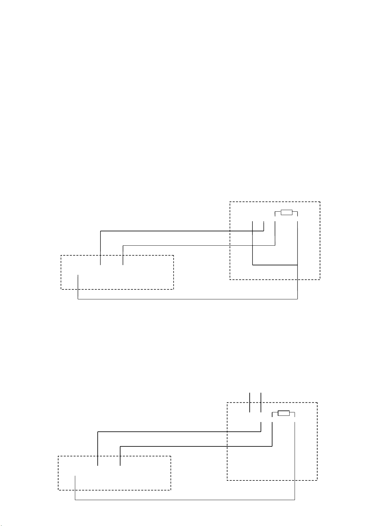
We suggest sensor get power supply separately to avoid power supply
instability if there has a long distance between DVR and sensor. We suggest
connected both side GND together to stable the power supply as follows:
DVR
+12V GND IN 1 IN 2
+12V
+ - NO C
Probe
Page 2
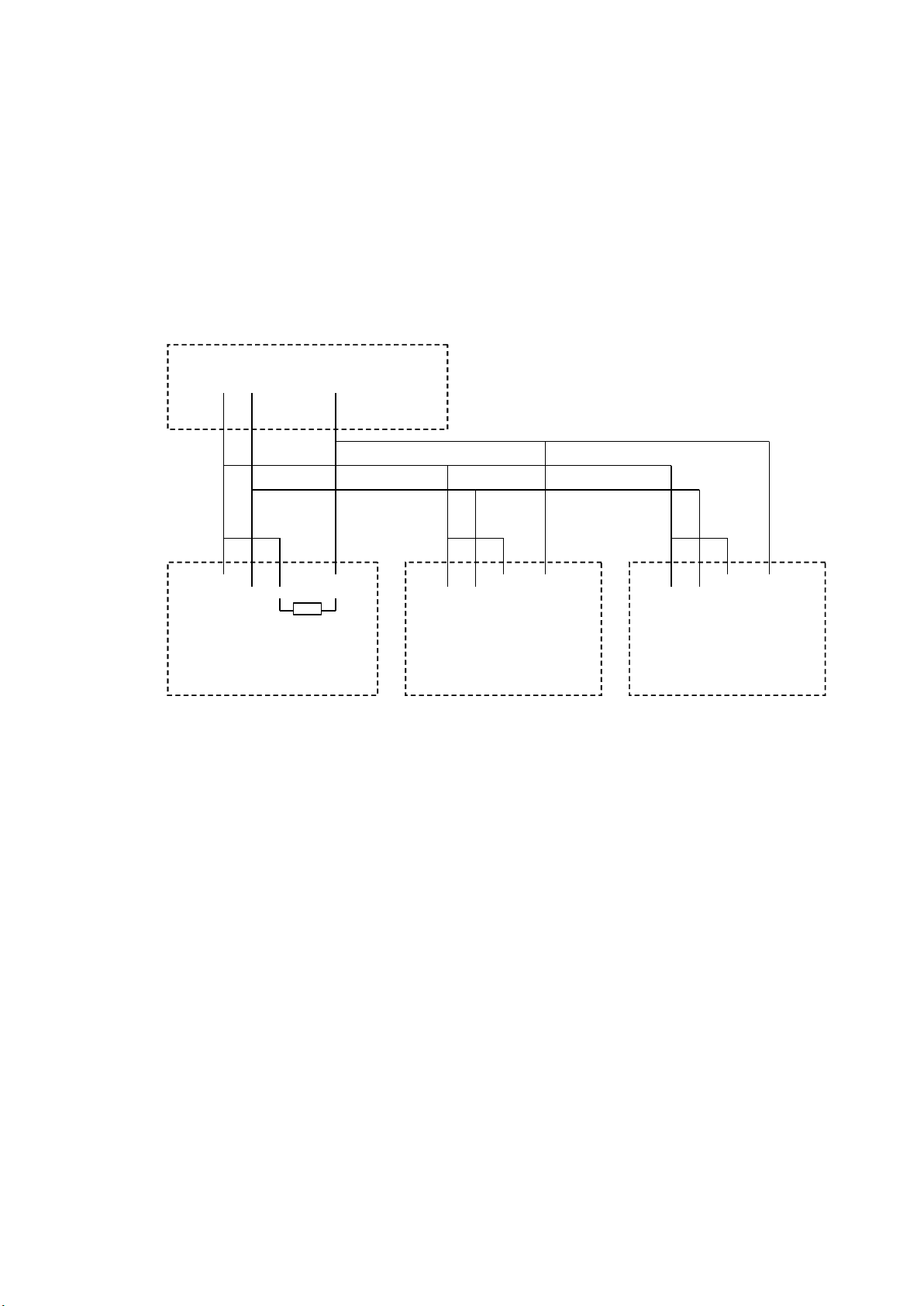
If user wants to parallel connected multi-sensor to host, the DVR can ’ t
recognize the triggered sensor. User needs to parallel connect this resistance
to all sensors as below fig.
+12V GND IN 1 IN 2
+ - C NO
Probe 1
DVR
+ - C NO
Probe 2
2. Alarm input normal on/off setting of software
+ - C NO
Probe 3
7000T series: Enter main interface — > record mode — > alarm record to
enter the interface as follows, and choose the open status of sensor type.
Page 3

8000T /8200T series: Enter the main interface->alarm setup-> alarm
output ,and choose the normal on status of sensor type.
3. Alarm output connection
When alarm happens, the main board will give a triggered voltage signal
to the alarm output equipment(loud speaker, light, etc
alarm. But the alarm equipment should has a separately power supply.
and make them output
)
Page 4

OUT 1A OUT 1B
DVR
Independent power supply
Alarm Speaker
There has an power consumption limit of external alarm equipment
7000T series
8000T/8200T series
The
excessive
The
excessive
The
The excessive
excessive power
01 : How to use the alarm function ?
Answer : Our system supports general sensors. ( e.g. smoke sensor, IR
sensor ) Outgoing On/off value transfers the signal to Server via alarm
processing module. And it can enable related recording or output the
On/Off value , all our products support normal open and normal close
working modes
① In case your sensor equipments are of high power consumption, to
avoid damaging the alarm output module, please make relay extension
connection.
240V/AC 7A, 125V/AC 10A, 28V/DC 10A
:
120V/AC 1A, 24V/DC 1A
:
power
power
power consumption
consumption
consumption
consumption may
FAQ
FAQ
FAQ
FAQ
may
may
may damage
damage
damage
damage main
main
main
main board.
board.
board.
board.
:
② In case you are using high frequency equipments, e.g. High frequency
lights please make relay extension connection method, or alarm module
may not work properly.
02
How to clear alarm
:
Answer
IR remote controller. If the host DVR is locked, please login first.
you can clear the alarms by pressing the “ alarm clear ” key on the
:
?
 Loading...