

Elin EBG ELVOvert SX Operating Manual
ELVOvert SX
Operating, Service
Projecting, Mounting & Connecting
8074667.02/02

Sicherheitshinweise
Folgende Symbole werden Sie durch die Anleitung begleiten:
Safety instructions
The following symbols should assist you in handling the instruction:
Allgemeiner Hinweis, Unbedingt beachten !
Gefährliche Spannungen ! Lebensgefahr !
Messung, Kontrolle !
Hinweis, Tip !
Bedienung über das Bedienfeld !
Beispiel !
Voraussetzung für eine erfolgreiche Inbetriebnahme sind eine
korrekte Geräteauswahl, Projektierung und Montage. Sollten Sie
in diesem Zusammenhang weitere Fragen haben, so wenden Sie
sich bitte an Ihre Vertriebsstelle oder direkt an den Lieferanten
des Gerätes.
Kondensatorentladung !
Vor Arbeiten am Gerät ist nach dem Freischalten vom Netz die
Kondensatorentladezeit von mindestens 5 Minuten abzuwarten
(Ladekontroll-LED auf der Platine !!), um sicherzustellen, daß das
Gerät völlig spannungsfrei ist.
Automatischer Wiederanlauf !
Bei bestimmten Parametereinstellungen kann es vorkommen,
daß der Frequenzumrichter nach einem Ausfall und anschließender Netzzuschaltung automatisch wiederanläuft. Stellen Sie
sicher, daß dadurch weder Personen noch Einrichtungen gefährdet sind.
Inbetriebnahme und Service !
Arbeiten am Gerät dürfen nur von dafür qualifizierten Personen
unter Beachtung der gültigen Bedienungsanleitung und
Vorschriften erfolgen. Im Fehlerfall können auch betriebsmäßig
potentialfreie Kontakte und/oder Baugruppen gefährliche
Spannungen führen. Um eine Gefährdung auszuschließen, sind
die Vorschriften ”Arbeiten unter Spannung” zu beachten.
Lieferbedingungen:
Unseren Lieferungen und Leistungen liegen die ”Allgemeinen
Lieferbedingungen der Elektro- und Elektronikindustrie Österreichs” neuester Ausgabe zugrunde.
Angaben in dieser Anleitung:
Es ist unser Bestreben, unsere Erzeugnisse ständig zu verbessern
und jeweils dem neuesten Stand der technischen Entwicklung
anzupassen. Änderungen der Angaben in dieser Anleitung, insbesondere von Maßen und Abmessungen, bleiben daher jederzeit vorbehalten. Die Projektierungshinweise und
Anschlußbeispiele sind unverbindliche Vorschläge, für die wir insbesondere deshalb keine Gewähr übernehmen können, da die
anzuwendenden Bestimmungen von Art und Ort der Installation
und Verwendung der Geräte abhängen.
Vorschriften:
Der Anwender hat sicherzustellen, daß das Gerät sowie
zugehörige Komponenten nach den jeweils gültigen Vorschriften
verwendet werden. Der Einsatz dieser Geräte in Wohngebieten
ist ohne besondere Maßnahmen zur Funkfrequenzentstörung
nicht zulässig.
Schutzrechte:
Wir bitten zu beachten, daß keine Gewähr dafür übernommen
wird, daß die hier beschriebenen Schaltungen, Geräte und
Verfahren frei von Schutzrechten sind.
Bewahren Sie diese Anleitung in
Gerätenähe jederzeit griffbereit auf !
General information, note exactly !
Dangerous voltages ! Danger of life !
Measurement, control !
Advise, tip !
Keypad operation !
Example !
The requirements for a successfull commissioning are a correct selection
of the unit, projection and mounting. In case of further questions, please
contact the supplier or call the manufacturer of the unit directly.
Capacitor discharge !
Before any work on or in the unit, disconnect from the mains and wait at
least 5 minutes until the D.C.link capacitors have been fully discharged.
Check that the device is no longer alive by measuring the voltage at the
D.C.link capacitor.
Automatic restart !
In case of certain parameter adjustments it may happen that the frequency inverter starts up automatically after switching on the mains
again. You have to guarantee, that no person and no other equipment
is in danger.
Commissioning and service:
Works on or in the unit must only be undertaken by properly qualified
staff in full compliance of the appropriate instructions and pertinent
regulations. Note that a fault may cause potential-free contacts and/or
PCBs to carry mains potential. To avoid any risk to humans, obey the
regulations concering ”Work on Live Equipment” explicitly.
Delivery conditions:
Our deliveries and services are based on the ”General Terms of Delivery
of the Austrian Electrical Industries” latest edition.
Specifications in this instruction:
We are constantly striving to improve our products and adapt them to
the latest state of technical development. We therefore reserve the right
to modify the specifications given in this instruction at any time, particulary those refering to measures and dimensions. All planning hints and
connecting samples are non-binding suggestions, for which we are unable to assume any liability, particulary since the regulations to be complied with depend on the type and location of the plant and on the use
of the instruments.
Regulations:
It is the users responsibility to ensure that the instrument and its component parts are used in compliance with applicable regulations.
It is not permitted to use these instruments in residential areas without
special measures to supress radio frequency interferences.
Patent and Trade Marks:
Please note that we do not guarantee any connections, instruments or
processes described herein to be free from patent or trademark right of
third parties.
Keep this instruction near the unit to
hand !

Operating & Service
Projecting, Mounting & Connecting
ELVOvertELVOvert SXSX
5,5(7,5) to 15(22) kW, 3 AC 380 to 460 V
8 074 667.02/02 / December 1998
ThemeTheme PagePage
Operating & ServiceOperating & Service 3 - 263 - 26
Projecting, Mounting & ConnectingProjecting, Mounting & Connecting 27 - 5027 - 50
Commissioning protocolCommissioning protocol A1 - A2A1 - A2
This documentation covers themes on operating, service, projecting, mounting and connecting.
It consists of the two main parts operating & service and projecting, mounting & connecting.
Regulations for the observance of the CE-directive and the new Power-Drive-Standard (EN 61800-3) are
described in the instruction manual „Additional installation regulations PX, SX“ (Cat.no. 8074578).
In case of damage or incomplete delivery, please inform the supplier or the insurance company.
The manufacturer declines responsibility for faults occurring during transport or unpacking.
SX - Operating- & Service instruction - 8 074 667.02/02 - page 1

Notes
SX - Operating- & Service instruction - 8 074 667.02/02 - page 2

Operating & Service instruction
ELVOvert SX
5,5(7,5) to 15(22) kW, 3 AC 380 to 460 V
ThemeTheme PagePage
Operation via the built-in keypad 4
Overview: actual value display 5
Overview: 1st level of operation 5
Overview: 2nd level of operation 6
Commissioning 7
Actual value displays d0 - d3, d10, d11 8
1st level of operation
F2, F4 9
F6, F7, F8, F9, F10 10
F11, F14 11
2nd level of operation
A0 12
A1 - A4 13
A5, A6 14
A7 - A14 15
A23 - A25 16
A26, A27, A34 17
A38 - A40, A44, A47, A48 18
A49, A54, A58, A59 19
A61 - A64 21
A80, A81, A86, A90 - A92, A94 - A96 22
A97 23
A98, C0 - C7 24
C10, C11, C20, C21 25
Notes 26
This documentation covers themes on operating, parameter setting and service. Themes on projecting, mounting
and connecting can be read in the projecting, mounting & connecting instructions starting on page 27.
Regulations for the observance of the CE-directive and the new Power-Drive-Standard (EN 61800-3) are
described in the instruction manual „Additional installation regulations PX, SX“ (Cat.no. 8074578).
In case of damage or incomplete delivery, please inform the supplier or the insurance company.
The manufacturer declines responsibility for faults occurring during transport or unpacking.
SX - Operating- & Service instruction - 8 074 667.02/02 - page 3

Operation via the built in operator panel
Example for the input of data
LED Display:
Shows frequency, motor current, DC-link voltage, motor
rotation direction and type.
FUNC-key:
Selects a basic parameter or
saves a changed parameter
value.
RUN-key:
Starts the inverter (only in
the keypad mode); not functional if the RUN-terminal is
activated.
STOP/RESET-key:
Stops the inverter or resets an existing trip.
Operates in the manual and in the terminal
mode but does not operate if parameters in
the 2nd level of operation are selected.
POWER-LED:
Shows if the electronic is working;
Attention: Use the charging LED
(right-sided to the connection terminals) to check the charging condition
of the DC-link.
UP/DOWN-key:
Changing of parameter values or
increasing/decreasing of the output
frequency.
Programming example for adjusting the frequency and starting of the inverter
There are 3 levels of operating the inverter:
1. The level of display of values is used to display operating parameters like e.g. actual-frequency and motor current.
2. In the 1st level of operation the frequency inverter can be programmed by usage of a few selected parameters.
3. The 2nd level of operation offers a lot of additional parameters which altogether can be modified only during standstill.
Overview of the actual value display and the 1st level of operation
Selecting and changing parameters in the 1st level of operation
Assuming that parameter d0 is selected (after mains-on often 0.00):
1) Switch to the parameter mode by pressing the FUNC-key.
2) Go through the parameter list by using the UP/DOWN-keys.
3) Select the parameter by pressing the FUNC-key.
4) Change it´s value by using the UP/DOWN-keys.
5) Confirm the change by pressing the FUNC-key.
SX - Operating- & Service instruction - 8 074 667.02/02 - page 4

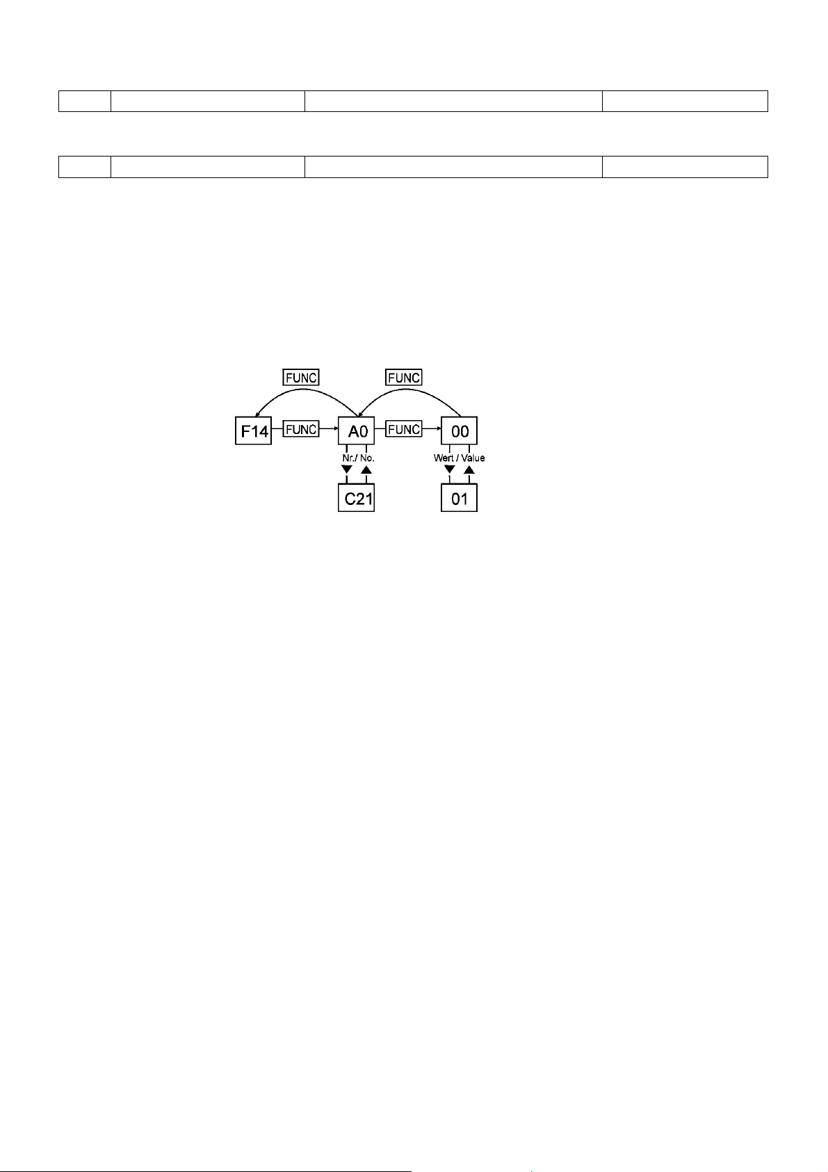
Selecting and changing parameters in the 2nd level of operation
Assuming that parameter d0 is selected (after mains-on often 0.00):
1) Switch to the parameter mode by pressing the FUNC-key.
2) Select parameter F14 using the UP/DOWN-keys.
3) Select the 2nd level of operation by pressing the FUNC-key.
4) Go through the parameter list by using the UP/DOWN-keys.
5) Select the parameter by pressing the FUNC-key.
6) Change it´s value by using the UP/DOWN-keys..
6) Confirm the change by pressing the FUNC-key.
7) Go back to the 1st level of operation (F14) by pressing the FUNC-key once more.
Remark:Remark:
After switching on the mains the parameter which was activated before switching off is displayed again.
Parameter
Overview of the actual value display and the 1st level of operation
Parameter nameParameter name No.No. RangeRange FDFD (Factory default)(Factory default) see pagesee page
Display of the output frequency d0 read only read only 8
Display of the motor speed x 100 d1 read only read only 8
Display of the motor current d2 read only read only 8
Display of the converted frequency d3 read only read only 8
Display of the last trip message d10 read only read only 8
Display of the trip memory d11 read only read only 8
Frequency reference & preset speeds F2 00.0- A63 Hz 0.00 9
Running direction selection F4 F or r F 9
Acceleration time F6 0.01-999 s 30 10
Deceleration time F7 0.01-999 s 30 10
Voltage boost F8 00-99 11 10
Operating mode (reference, start/stop) F9 00-15 03 10
Analogue meter adjustment F10 00-250 172 10
Nominal motor voltage F11 380,400,415,440,460 V 400 11
2nd level of operation F14 all parameters of the 2nd
level of operation *) 11
*) Only in the factory default setting (FD) and only if selected the first time, F14 will show A0.
In all other cases the last adjusted parameter is displayed under F14.
SX - Operating- & Service instruction - 8 074 667.02/02 - page 5

Overview of the 2nd level of operation
Parameter nameParameter name No.No. RangeRange FDFD see pagesee page
Operating methode A0 0-5 0 12
Motor capacity setting A1 4.0- 160 kW Nominal power 13
Pole number A2 2, 4, 6, 8 poled 4 13
Speed response A3 0.00-100 2.00 13
Starting frequency A4 0.10-9.99 Hz 0.50 13
f-MAX limitation A5 00.0- A63 Hz 0.0 14
f-MIN limitation A6 00.0- A63 Hz 0.0 14
Skip frequency 1 A7 00.0- 400 Hz 0.0 15
Skip frequency 2 A8 00.0- 400 Hz 0.0 15
Skip frequency 3 A9 00.0- 400 Hz 0.0 15
Carrier frequency A10 2.0-16.0 kHz 16 8) 15
Frequency command sampling A11 1-8 8 15
Preset speed 1 A12 00.0- A63 Hz 0.0 15
Preset speed 2 A13 00.0- A63 Hz 0.0 15
Preset speed 3 A14 00.0- A63 Hz 0.0 15
Elektronic motor protection A23 20-120% 100 16
Motor protection characteristic A24 0, 1, 2 0 16
Motor pole number for d1 A25 02, 04, 06, 08, 10, 12...48 04 16
Ext. f-ref limitation: start value A26 00.0- A63 Hz 0.0 17
Ext. f-ref limitation: end value A27 00.0- A63 Hz 0.0 17
Restart selection A34 0-3 0 17
Braking unit: usage ratio A38 0.0-100% 1.5 18
Signal „Frequency arrival“: On-level A39 00.0- A63 Hz 0.0 18
Signal „Frequency arrival“: Off-level A40 00.0- A63 Hz 0.0 18
Analogue output f/I/T A44 0-3 0 18
Calculation factor n A47 0.0 - 99.9 1.0 18
Frequency reference selection A48 0, 1 1 18
„Frequency arrival“ characteristic A49 0, 1, 2 0 19
Speed search function A54 0, 1 1 19
Start with reduced voltage A58 0-06 6 19
Mode of operation A59 0, 1, 2 0 19
JOG-frequency A61 0.00-9.99 Hz 1.00 21
Base frequency A62 30- A63 Hz 50 21
End frequency A63 30-120(400)Hz 50 21
Maximum frequency A64 120, 400 Hz 120 21
Calibration of f-reference. voltage A80 0...255 pre-adjusted !! 22
Calibration of f-reference. current A81 0...255 pre-adjusted !! 22
Reset input performance A86 0, 1 0 22
PID-controller: P-gain A90 0.1 - 5.0 1.0 22
PID-controller: I-gain A91 0.0 - 15.0 s 1.0 22
PID-controller: D-gain A92 0.0 - 100.0 0.0 22
PID-controller: selection A94 0 - 4 0 22
PID-controller. reference A95 0, 1 0 22
PID-controller: internal reference A96 0.0 - 200 % 0.0 22
Auto-Tuning A97 0 - 2 0 23
Motor data selection A98 0 - 2 0 24
Input phase supervision A99 0, 1 0 = ON 24
Setting for input 1 C0 0...28 18 24
Setting for input 2 C1 0...28 16 24
Setting for input 3 C2 0...28 5 24
Setting for input 4 C3 0...28 11 24
Setting for input 5 C4 0...28 9 24
Setting for input 6 C5 0...28 2 24
Setting for input 7 C6 0...28 1 24
Setting for input 8 C7 0...28 0 24
Setting for output terminal 11 C10 0-2 0 25
Setting for output terminal 12 C11 0-2 1 25
Inputs 1-4: Inversion C20 00-09, 0A-FF 08 25
Outputs 11,12 & relay: inversion C21 00-07 04 25
SX - Operating- & Service instruction - 8 074 667.02/02 - page 6

Commissioning
Before start of commissioning please notice the following items:
1. Check the correct connection of mains- and motorlines.
2. Check if the control lines are connected with the correct terminals.
3. Check if the frequency inverter is correctly grounded according to regulations and mounted vertically to a wall.
4. Remove all stray pieces of wire, solderless terminals or other objects left from wiring work.
5. Check if all screws and terminals are fixed.
6. Check if the motor is specified for the defined frequency range in particular for the maximum speed.
7. For optimum adaptation of the frequency to the motor see parameter A97, Auto-Tuning.
Factory default setting (Initialisation)
At delivery all frequency inverters of the series ELVOvert SX are preset to factory default. The devices can be reset to this
basic setting any time.
To do so, proceed the following steps:
1. Switch the power on (display 0 0 0) and press the FUNC-key once (display d 0).
2. Select parameter F14 by repeatedly pressing the arrow keys.
3. Press the FUNC-key once. Parameter A0 is displayed.
4. Select one of the parameters C0 - C7 (corresponding to the terminals 1- 8, e.g. C1 = input 2) via repeatedly pressing
the arrow keys and press key FUNC once.
5. Put in parameter 7 under this parameter by usage of the arrow keys (terminal function STN = factory default setting)
and store the input via pressing the FUNC-key once.
6. The terminal which is selected by this procedure is now used to activate setting to factory default. Connect this terminal
to terminal P24 and switch off power. Wait as long as the LED which monitors the link voltage is switched off.
7. Switch on power again and wait for appr. 6 sec.
8. Disconnect the link between the terminal for factory default setting and terminal P24.
9. Switch off power again and wait until the LED which monitors the link voltage is switched off.
Commissioning via built-in keypad
Remark:Remark:
The inverter needs “Pulse unlocked“ to rotate the motor. Terminal 4 is from manufacturing preset with “Pulse unlocked“
and therefore has to be connected with P24 via a linking wire. Additionally a wire to link PLC with CM1 is required.
1. Switch on the power; the power-LED on the operator panel is then on (display shows value of d 0).
2. Select parameter F4 by repeatedly pressing the arrow keys. Press the FUNC-key. Now you can select the required
direction of rotation by usage of the arrow keys (F = forward, r = reverse). Store the input by pressing the key FUNC.
3. Select parameter F9 via pressing the arrow keys and put in 00 on this parameter position (see parameter F9).
4. Now selecet parameter F2 and adjust the set frequency by usage of the arrow keys.
5. Start the inverter via the RUN key.
SX - Operating- & Service instruction - 8 074 667.02/02 - page 7

Description of the actual value display area
The level of “Display of the actual values“ offers the user important operating data (e.g. motor current, link voltage, ...). In
addition it supports the analysis in case of a failure.
d 0 Output frequency Hz read only
The parameter shows the actual output frequency in Hz. Display during stand-still: 0.00
In the range from 0,01 to 9,99 Hz the display cycles in 0,01 Hz steps, between 10 and 99,9 Hz in 0,1 Hz steps
and from 100 Hz to 400 Hz in 1 Hz steps.
d 1 Motor speed x 100 rpm read only
The parameter shows the calculated motor speed. As the frequency inverter cannot measure the actual speed of
the slipping motor, if no speed feedback is used, this value is theoretical.
Display during stand-still: 0.00. Pay attention to the adjustment of parameter A25 „Motor pole
number for d1“ !
Speed range Display Steps
1 to 999 rpm 0,01 to 9,99 0,01 rpm
1000 to 9990 rpm 10,0 to 99,9 0,1 (10 rpm)
10000 to 60000 rpm 100 to 600 1 (100 rpm)
d 2 Motor current A read only
The parameter shows the output current of the inverter (=motor current) with an accuracy of +/- 10%
according to the upper limit value. Display during stand-still: 0.0
From 0,1 to 99,9 A the display cycles in 0,1 A steps and from 100 to 999 A in 1 A steps.
d 3 Converted frequency read only
The parameter shows the result of the output frequency d0 multiplied by the value of A47.
Anzeige Werte
0.0 - 9.99 0.0 - 9.99
10.0 - 99.9 10.00 - 99.99
100. - 999. 100.00 - 999.99
100 - 999 1000.00 - 9999.99
10 - 39 10000.00 - 39960.00
d10 Last trip message read only
The last trip, the relevant output current and the link voltage (x10) are stored under this parameter and can be
read out with the FUNC-key.
Display:_ _ _ Up to now no trips have occurred and the trip memory is erased.
Display: 0.00 Display after reset
d11 Trip memory read only
The 2nd and 3rd last trip message are stored under this parameter. With pressing the FUNC-key they can be
displayed in turn. The trip memory can be erased with the external control unit BE-4.
Display :_ _ _ In this storage position no trip message is stored.
SX - Operating- & Service instruction - 8 074 667.02/02 - page 8
Description of the 1st level of operation
F2 Frequency ref. value, 00.0 - A63 Hz FD: 00.0 Hz
Preset speeds
At any time Parameter F2 displays the frequency set value as an actual value which is adjustable, if F9 is
programmed in a suitable way, via the keys of the operator panel.
The inverters of the ELVOvert SX series offer the following choices to define a frequency reference value:
Set value definition via the keys of the built in operator panel.
Adjustment of this set-value by the use of motorpotentiometer up or motorpotentiometer down dig. inputs
Manual set value via the analogue input 0 ...10 V
Automatic set value via analogue input 4 ... 20 m A
3 or 7 preset speeds
(Set value definition via the key of the external control unit BE-4)
(Analogue or digital definition of set-value via one of the option boards)
Frequency reference value via keypad (F9 and F2)
For the definition of the frequency set value via the keys of the built in operator panel under parameter F9 = 00
or 02 has to be set.
Frequency range Steps
0,01 to 9,99 Hz 0,01 Hz
10 to 99,9 Hz 0,1 Hz
100 to 400 Hz 1 Hz
Permanently pressing one of the arrow keys results in continuous increase or decrease of the set value.
Preset speeds (C0 to C7; as an alternative for adjusting A12, A13 and A14)
In factory setting the digital inputs 6 and 7 (dedicated to the terminal functions CF1 and CF2) are defined to select the pre-set speeds 1 - 3. (For the pre-set speeds 4 - 7 the terminal function CF3 is required; for programming of this please see parameter C0 - C7.)
Function CF1 CF2 CF3
1. preset speed ON OFF OFF
2. preset speed OFF ON OFF
3. preset speed ON ON OFF
4. preset speed ON OFF ON
5. preset speed OFF ON ON
6. preset speed ON ON ON
7. preset speed OFF OFF ON
Adjustment of the preset speeds during operation:
After selection of the relevant preset speed by use of the terminal function CF1-CF3 the desired frequency can
be adjusted via the UP/DOWN-keys (factory default setting 000).
Store the frequency which was set by pressing the FUNC-key.
Alternatively the pre-set speeds 1 - 3 also can by defined via the use of the parameters A12, A13 and A14.
Remark:Remark:
Frequencies above 120 Hz can be only adjusted if the parameter A64 „Maximum frequency“ is set to 400 Hz !!
F 4 Running direction select. F (FWD) , r (REV) FD: F
After pressing the RUN key the motor starts with the direction of rotation which is defined by this parameter.
This parameter does not influence the control inputs.
SX - Operating- & Service instruction - 8 074 667.02/02 - page 9

F 6 Acceleration time 0.01 - 999 s FD: 30
F 7 Deceleration time 0.01 - 999 s FD: 30
The acceleration- or deceleration time references to the defined end frequency (parameter A63).
Remarks:
The 2nd acceleration and deceleration time is set by F6 and F7, if the function CH1 (2nd ramps) is selected
The acceleration and deceleration time for the 2nd set of parameters is set by F6 and F7, if the function SET
Means that behind the parameters F6 and F7 three independently adjustable ramp times are hidden.
F 8 00 - 99 FD: 11
torque is boosted. Care has to be taken that the motor is not overloaded. A voltage boost which is adjusted to a
too great level may cause a trip (overcurrent) of the inverter.
Remark:Remark:
Voltage boost does not operate in SVC-mode (A0 set to 4 or 5) !!
F9 Operating mode 00 - 15 FD: 03
(reference, start, stop)
This parameter defines in which way the set value or the start/stop-signal is presented to the inverter.
Value Start/Stop-Signal Reference
00 Keypad Keypad*)
01 Keypad Terminals
02 Terminals Keypad*)
03 Terminals Terminals
04 Keypad Option1
05 Option1 Keypad*)
06 Option1 Option1
07 Keypad Option2
08 Option2 Keypad*)
09 Option2 Option2
10 Terminals Option1
11 Option1 Terminals
12 Terminals Option2
13 Option2 Terminals
14 Option1 Option2
15 Option2 Option1
*) One of these adjustments must be selected to use the motorpotentiometer function !!!
F10 Analogue meter adjust. 00 - 250 FD: 172
Adjustment of the analogue signal on terminal FM (frequency set-value, output current, torque).
An adjustment of the pulse signal (frequency actual value) is not possible.
The value which is put in by this parameter is maintained during reset to factory defaults (terminal function STN).
The max. output voltage (10 V) of the terminal means:
- at display of the frequency the end frequency (parameter A63)
- at display of the current 200% of the inverter´s nominal current
- at display of the torque 200 % of the motor’s nominal torque
SX - Operating- & Service instruction - 8 074 667.02/02 - page 10
F11 Nominal motor voltage 380/400/415/440/460 V FD: 380
Select the nominal voltage of the connected motor.
F14 2nd level of operation Parameters of the 2nd level FD: A0 *)
If the application requires more advanced parameters F 2 - F11 then by the use of F14 the 2nd level of operation can be selected. The 2nd level of operation offers a range of further parameters (A0 - A 65) and also the
choice to program inputs and outputs according to the requirements (C 0 - C21). With the key FUNC you may
return from every parameter of the 2nd level of operation to F14. After input of data has been completed pressing of key FUNC once stores the new data and another function can be selected.
Remark:
All parameter changes in the 2nd level of operation can only be performed during stand-still after releasing a
stop command.
Scheme:Scheme:
*) Only in the factory default setting and only if selected the first time, F14 will show A0.
In all other cases the last adjusted parameter is displayed under F14.
SX - Operating- & Service instruction - 8 074 667.02/02 - page 11

Description of the 2nd level of operation:
A0 Operating methode 0 - 5 FD: 0
Frequency inverters of the ELVOvert SX series offer three different control methods:
V/f-characteristics for standard torque requirements and multi motor operation.
Sensorless Vector Control (SVC) for great torque especially at low frequencies (<5 Hz) and dynamic
compensation of slip with the usage of speed feedback. Using the operating data (output current, cos ϕ)
the frequency inverter for every load condition calculates the optimum output voltage or output frequency.
Vector Control (V2) with speed feedback using a pulse sensor or an incremental sensor for applications
which demand absolute accuracy of speed and angle (only with option board).
Remark:Remark:
At the choice of 1, 2 or 3 the inverter automatically is switched to increased output power “P“.
Value Parameter V/f-characteristic
0 V/f -characteristic,
constant torque
„C“
1 V/f-characteristic
reduced torque
V/f VP1, M = n
1,5
„P“ for fans, pumps, ...
(2) V/f-characteristic
reduced torque
V/f VP2, M = n
1,7
„P“
(3) V/f-characteristic
reduced torque
V/f VP3, M = n
2
„P“
4 Sensorless Vector Control SVC
„C“ for conveyors, chassis drives,...
5 Vector Control with feedback V2
(with optinal PCB only
„C“
For pos. 4 and 5 the correct adjustment of A1, A2 and A3 is essential !
The frequency inverter should be adapted optimally to the motor independent of the selected control method.
See parameters F11, A1, A2, A10, A97, A62, A64.
SX - Operating- & Service instruction - 8 074 667.02/02 - page 12

A 1 Motor capacity setting 4.00 - 160 kW FD: Nom. „C“
A
/
]
0
99
A 2 Pole number 2, 4, 6, 8 pole FD: 4
Put in the nominal power and number of poles of the motor to achieve great motor efficiency. If the data stored
under this parameters do not comply with the actual motor data then especially in the case of the control
method SVC the drive cannot be utilised optimally.
Remarks:Remarks:
About optimum adaptation to the motor see parameter A64 !!
To show the correct speed in d1 it is necessary to set parameter A25 to the correct value !!
A 3 Speed response 0.00 - 100 FD: 2.00
This parameter is only valid for the control method SVC. It caters for the dynamic stabilisation this means that
speed remains constant even during changing of motor load.
An increase of the parameter value causes increased time to react, decreasing reduces the time to react on
changes of the slip or load.
A 4 Starting frequency 0.10 - 9.99 Hz FD: 0.50
The start frequency can be adjusted between 0.12 Hz and 9.99 Hz in Steps of 0.01 Hz.
An increase of the start frequency results in a decrease of the acceleration- or deceleration time.
An increase of the start frequency may be required e.g. to overcome remarkable friction of the drive or of the
attached machine.
Remark:Remark:
Too great setting of start frequency may cause overcurrent trips.
usgangsspannung
Output voltage [V]
Ausgangsfrequenz /
0.19.
Output frequency [Hz
SX - Operating- & Service instruction - 8 074 667.02/02 - page 13
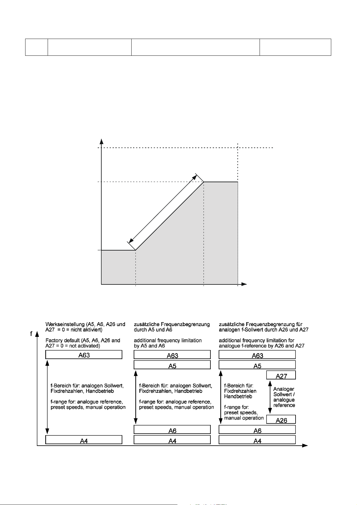
A 5 f-MAX limitation 0.0 - A63 Hz FD: 0.0
F-Sollwert [Hz] /
040
0
A 6 f-MIN limitation 0.0 - A63 Hz FD: 0.0
The frequency range which is defined by the values stored under parameter A4 (start frequency) and A63 (end
frequency) can be reduced via the parameters A5 and A6. The frequency inverter in this case only accepts set
values via the set value inputs or via the built in operator panel or the external control unit BE-4 which are within
this frequency range. As soon as the inverter gets a start command it runs to the frequency which is set via A6.
Remarks:Remarks:
At input of 0 Hz for A5 and A6 or A5 < A6 the relevant parameter is not active.
Frequencies > 120 Hz can only be adjusted if parameter A64 „Maximum frequency“ is set to 400 Hz !!
Ausgangsfrequenz /
output frequency
A5
A6
0
[Hz]
/
h
c
i
e
r
e
b
e
z
g
n
n
e
a
u
r
q
y
e
r
c
F
n
r
e
e
u
t
l
q
l
e
e
r
t
f
s
d
e
e
g
t
n
s
i
u
E
j
d
a
2
f-reference [Hz]
SX - Operating- & Service instruction - 8 074 667.02/02 - page 14

A 7 Skip frequency 1 0.0 - 400 Hz FD: 0.0
A 8 Skip frequency 2 0.0 - 400 Hz FD: 0.0
A 9 Skip frequency 3 0.0 - 400 Hz FD: 0.0
To avoid resonances eventually occurring in the drive system there is the possibility to program 3 lock out
frequencies.
Remarks:Remarks:
Locked out ranges are not skipped but crossed following the ramps.
Frequencies > 120 Hz can be only adjusted if parameter A64 „Maximum frequency“ is set to 400 Hz !!
The lock out width (+/- 0.5 Hz) can be varied with the external control unit BE-4 within 0.5 Hz to 9.9 Hz.
A10 Carrier frequency 2.0 - 16.0 kHz FD:16(8) *)
Adjusts the switching frequency in steps of 0,1 kHz in the range of 2 kHz up to 16 kHz.
*) 16 kHz at „C“-applications (A0=0, 4 or 5) The parameter is automatically set to the lower value but
8 kHz at „P“-applications (A0=1, 2 or 3) will not be set back to the higher value if A0 is changed.
This must be done manually.
Remarks:Remarks:
With lower switching frequencies in the control method SVC - especially in the case of frequencies <5Hz - a
greater speed accuracy of the motor can be achieved than with great switching frequencies!
Great switching frequencies cause less motor noise and decreased losses in the motor.
To decrease the interferences which are caused by the motor cables, the switching frequency should be kept
as low as possible.
A11 Freq. command sampling 1 - 8 FD: 8
Via the usage of the parameter A11 the sample rate of the set frequency inputs can be adjusted.
(Presentation as voltage input via terminals O-L, presentation by current value via OI-L).
The parameter may be varied between 1 and 8.
1 means a short time constant (great sample rate) which of course is coupled with quick variations of the signal
which may be not acceptable. The maximum value 8 in contrary means slow speed of reaction but on the other
hand a stable output frequency.
A12 Preset speed 1 0.0 - A63 Hz FD: 0.0
A13 Preset speed 2 0.0 - A63 Hz FD: 0.0
A14 Preset speed 3 0.0 - A63 Hz FD: 0.0
Adjustment of up to 7 preset speeds (alternatively to F2).
Each of them can be seperately activated by linking one of the terminals CF1 to CF3 with P24:
PresetPreset CF1CF1 CF2CF2 CF3CF3 Remarks:Remarks:
1 ON OFF OFF To use the preset speeds 4 to 7 it is necessary
2 OFF ON OFF to assign the function CF3 to one of the programmable
3 ON ON OFF digital inputs 1-8.
4 ON OFF ON The values for the preset speeds 4-7 can be only
5 OFF ON ON adjusted via the operating unit BE-4 (parameter F-11).
6 ONONON Preset speeds will always overrule the actual reference
7 OFF OFF ON value independent of the adjustment of F9.
SX - Operating- & Service instruction - 8 074 667.02/02 - page 15
 Loading...