

Elimko E-PR-110 Series, E-PR-110-1-1-1-1-0-0, E-PR-110-1-1-3-3-0-0, E-PR-110-1-1-1-5-1-0, E-PR-110-4-4-4-5-1-0 User Manual
...
Manufacturer / Technical Support
Elimko Electronic Production and Control Co. Ltd.
8. Avenue 68. Street No:16 06510 Emek- Ankara / TURKEY
Phone: + 90 312 212 64 50 Fax: + 90 312 212 41 43
www.elimko.com.tr / e-mail:elimko@elimko.com.tr
E-PR-110
Paperless Recorder
User Manual
Manufacturer / Technical Support
Elimko Electronic Production and Control Co. Ltd.
8. Avenue 68. Street No:16 06510 Emek- Ankara / TURKEY
Phone: + 90 312 212 64 50 Fax: + 90 312 212 41 43
www.elimko.com.tr / e-mail:elimko@elimko.com.tr

K - Q
TSE-ISO-EN
9000
TS EN ISO 9001
Quality Management System Certificate
KY-PR110-0417-1
1 - INDEX
1. INDEX
2. FIGURES
3. WARNINGS
4. DESCRIPTION
4.1. Type Coding
4.2. Technical Specification
4.3. Dimensions
4.4. Panel Mounting
5. USAGE
5.1. Front Panel
5.2. Trend Page
5.3. Bar Graphic Page
5.4. Digital View Page
5.5. Overview Page
5.6. Alarm Log
5.7. Totalizer Log
5.8. Instrument Log
5.9. Operator Log
5.10. Digital Log
5.11. Digital 2
6. MENU PAGES
6.1. Adjusting Parameters
6.2. Main Menu
6.3. Device Page
6.4. Security Page
6.5. Hardware Page
6.5.1. Slot Adjustments
...............................................................................................................
.........................................................................................................
......................................................................................................
................................................................................................
..................................................................................................
....................................................................................................
.............................................................................................
............................................................................................................
....................................................................................................
....................................................................................................
..........................................................................................
...........................................................................................
..............................................................................................
......................................................................................................
.................................................................................................
..............................................................................................
.................................................................................................
...................................................................................................
........................................................................................................
..................................................................................................
.....................................................................................................
..................................................................................................
................................................................................................
.............................................................................................
.........................................................................................
..................................................................................
....................................................................................
1
1 - 2
3 - 6
7
8
9
10 - 11
12
13
14
14 - 16
17 - 20
21
22 - 23
24
25
26
27
28
29
30
31
32
33
34
35
36
36 - 41

1 - INDEX
6.5.2. Ethernet Ayarları
6.5.3. Seri Port Ayarları
6.5.4. Ekran Ayarları
6.6. Kanallar
6.6.1. Röle Kartı Ayarları
6.6.2. Sayısal Çıkış Kartı Ayarları
6.6.3. Analog Giriş Kartı Giriş Ayarları
6.6.4. Analog Çıkış Kartı Ayarları
6.6.5. Alarm Ayarları
6.6.6. Toplayıcı Ayarları
6.6.7. Kayıt Ayarları
6.6.8. Sayısal Giriş Kartı Ayarları
6.6.9. Modbus Kanalları Sayfası
6.6.10. Matematik Kanal Ayarları
6.7. Gerçek Zaman Kanalları
6.8. Gruplar
6.9. Kullanıcı Tanımlı Tablolar
6.10. Arşiv
6.11. E-mail
6.12. PID
7. BAĞLANTI ŞEMALARI
8. VERİ TRANSFERİ VE İLETİŞİM PROTOKOLLERİ
9. EKLER
EK 1 Ethernet Bağlantısı
EK 2 Math Editor ile Eşitlik Girilmesi
EK 3 Modbus RTU İletişim Adresleri
EK 4 Barkod Okuyucu
.........................................................................................................
...........................................................................................................
.............................................................................................................
..........................................................................................................
.............................................................................................................
..............................................................................................................
.........................................................................................
.........................................................................................
..............................................................................................
.......................................................................................
..........................................................................
...................................................................
...........................................................................
..............................................................................................
.........................................................................................
...............................................................................................
...........................................................................
............................................................................
...........................................................................
................................................................................
...............................................................................
.....................................................................................
......................................................................................
....................................................................
....................................................................
..........................................................................................
2 3
.........................................
42
43
44
45
46
47
48 - 52
53 - 54
55 - 57
58
59 - 60
61
62 - 64
65
66 - 67
68
69
70 - 72
73 - 76
77 - 84
85 - 91
92 - 93
94
94 - 95
96 - 98
99
100
2 - FIGURES
Şekil 4.1 E-PR-110 boyutları ve pano montaj aparatı
Şekil 4.2 E-PR-110 Panel Kesiti
Şekil 5.1 Trend Görünümü
Şekil 5.2 Operasyon tuşları
Şekil 5.3 Trend Görünüm Ekranı
Şekil 5.4 Trend görünüm ekranında aktif butonlar ve anlamları
Şekil 5.5 Trend görünüm ekranındaki aktif butonlar ve seçenekleri
Şekil 5.6 İşlem başlat ekranı
Şekil 5.7 Bar görünüm ekranı
Şekil 5.8 Sayısal görünüm ekranı
Şekil 5.9 Sayısal görünüm ekranında toplayıcı resetleme
ve operatör mesajı ekleme
Şekil 5.10 Toplu görünüm ekranı
Şekil 5.11 Alarm Log ekranı alarm durumu
Şekil 5.12 Toplayıcı Log ekranı
Şekil 5.13 Cihaz Log ekranı
Şekil 5.14 Operatör Log ekranı
Şekil 5.15 Sayısal Log ekranı
Şekil 5.16 Sayısal 2 ekranı
Şekil 6.1 Ana Menüye giriş şifre penceresi
Şekil 6.2 Ana Menü
Şekil 6.3 Cihaz Bilgileri Sayfası
Şekil 6.4 Tarih – Saat Ayarlama Sayfası
Şekil 6.5 Güvenlik Ayarları Sayfası Admin Ayarı
..............................................................................................
............................................................................
....................................................................................
...................................................................................
...........................................................................
..................................................................................
................................................................................
..........................................................................
.....................................................................
...........................................................................
...........................................................
.............................................................................
..................................................................................
.............................................................................
................................................................................
....................................................................................
...........................................................
............................................................................
...............................................................
...........................................
............................
.................................................
......................
12
13
14
15 - 16
17
18
19
20
21
22
22
23
24
25
26
27
28
29
30
31
33
34
34
35
2 - FIGURES2 - FIGURES
Şekil 6.6 Güvenlik Ayarları Sayfası Kullanıcı Ayarı
Şekil 6.7 Donanım Slot Ayarları Sayfası
Şekil 6.8 Donanım Röle Çıkış Test Sayfası
Şekil 6.9 Donanım Analog Giriş Kartı Kalibrasyon Sayfası
Şekil 6.10 Donanım Analog Çıkış Kartı Kalibrasyon Sayfası
Şekil 6.11 Donanım Ethernet Sayfası
Şekil 6.12 Donanım Ethernet Sayfası
Şekil 6.13 Donanım Seri Port penceresi
Şekil 6.14 Donanım Ekran Ayarları penceresi
Şekil 6.15 Çizim Opsiyonları penceresi
Şekil 6.16 Renk Seçim penceresi
Şekil 6.17 Slot Kanalları sayfası
Şekil 6.18 Röle Kartı Ayarları
Şekil 6.19 Sayısal Çıkış Kartı Ayarları
Şekil 6.20 Analog Giriş Kartı Giriş Ayarları
Şekil 6.21 Giriş Tipi Seçimi
Şekil 6.22 Termokupl seçimi
Şekil 6.23 Rezistans Termometre seçimi
Şekil 6.24 Giriş tipi Ohm, Milivolt, Miliamper ya da
Volt seçilmiş ise Lineerleyici seçimi
Şekil 6.25 Giriş tipinin Termokupl seçili olmaması durumunda
CJ Tipi, CJ Sıcaklık ve CJ Kaynak parametreleri
Şekil 6.26 CJ Tip seçim durumlarına göre CJ Sıcaklık ve
CJ Kaynak parametlerinin durumu
................................................................................
...................................................................................
..................................................................................
................................................................
...........................................................
....................................................................
....................................................................
...............................................................
.................................................................
.........................................................................
............................................................................
...................................................................
...........................................................
...............................................................
...........................................
....................................
.......................................................
......................................................
.......................................................
4 5
................................
.................................
35
36
37
38
40
42
42
43
44
44
44
45
46
47
49
50
50
50
50
50
51
27
52
28
Şekil 6.27 Analog Çıkış Kartı Kaynak Proses Değeri
ile Çıkış Değeri Değişimi
Şekil 6.28 Analog Çıkış Kartı Ayarları
Şekil 6.29 Alarm 1 Seçimleri
Şekil 6.30 Alarm 2 Seçimleri
Şekil 6.31 Alarm Tip Seçimleri
Şekil 6.32 Low ve High Alarm Formları
Şekil 6.33 Slow Rate ve Fast Rate Alarm Formları
Şekil 6.34 Analog Giriş Toplayıcı ayarları
Şekil 6.35 Analog Giriş Kayıt ayarları
Şekil 6.36 Sayısal Giriş Kartı Giriş ayarları
Şekil 6.37 Sayısal Giriş Kartı Kayıt ayarları
Şekil 6.38 MODBUS Kanalları Sayfası
Şekil 6.39 Reg. Tipi seçenekleri
Şekil 6.40 Matematik Analog Sayfası
Şekil 6.41 Matematik Sayısal Sayfası
Şekil 6.42 Gerçek Zaman Kanalları (RTC) Sayfası
Şekil 6.43 Gerçek Zaman Kanalları (RTC) kaynak seçimi
Şekil 6.44 Gerçek Zaman Kanalları (RTC) periyod seçimi
Şekil 6.45 Gruplar Sayfası
2
Şekil 6.46 Gruplar Sayfası Grup seçimi
Şekil 6.47 Kullanıcı Tanımlı Tablolar Sayfası
Şekil 6.48 Analog Giriş sayfasında tablo seçimi
Şekil 6.49 Arşiv Senkronizasyon Sayfası
....................................................................................
....................................................................
.................................................................................
.................................................................................
..............................................................................
.................................................................
..............................................................
....................................................................
...........................................................
..........................................................
.................................................................
............................................................................
....................................................................
...................................................................
................................................................
..............................................................
...........................................
...............................................
..............................................
....................................
....................................
........................................................
...................................................
53
29
54
56
56
56
57
57
58
59
61
61
64
64
65
65
67
67
67
68
68
69
69
72
3 - WARNINGS2 - FIGURES
Şekil 6.50 Arşiv Yedek Sayfası
Şekil 6.51 E-MAIL Sunucu Sayfası
Şekil 6.52 E-MAIL Alıcılar Sayfası
Şekil 6.53 E-MAIL Kaynaklar Sayfası
Şekil 6.54 E-MAIL Olaylar Sayfası
Şekil 6.55 PID Kontrol Kanalları Sayfası
Şekil 6.56 PID Kaynağın Analog Çıkışa Tanımlanması
Şekil 6.57 PID Kaynağın Röle Çıkışa Tanımlanması
Şekil 6.58 PID Kontrol Trend Görünüm
Şekil 6.59 PID Kontrol Set Noktasının Değiştirilmesi
Şekil 6.60 Toplu Görünüm Sayfası
Şekil 7.1 E-PR-110 Arka Panel
Şekil 7.2 Güç, Transmitter Besleme, RS-485 ve Ethernet Bağlantıları
Şekil 7.3 3 Kanallı Analog Giriş Kartı Bağlantı Şemaları
Şekil 7.4 6 Kanallı Analog Giriş Kartı Bağlantı Şemaları
Şekil 7.5 Sayısal Giriş ve Çıkış Kartı Bağlantı Şemaları
Şekil 7.6 Röle Çıkış Kartı Bağlantı Şeması
Şekil 7.7 Analog Çıkış Kartı Bağlantı Şeması
Şekil 9.1 Röle Çıkışı Kartı Bağlantı Şeması
Şekil 9.2 RJ 45 pin numaraları ve Crossover kablo bağlantısı
Şekil 9.3 MATH EDITOR Sayfası
Şekil 9.4 Script tuş seçimleri
Şekil 9.5 Operatör ve Fonksiyon Açıklamaları
Şekil 9.6 MODBUS Tablosu
Şekil 9.7 Sayısal Veri Bit Yerleşimi
..............................................................................
........................................................................
.........................................................................
....................................................................
........................................................................
...............................................................
.........................................
.............................................
.................................................................
............................................
........................................................................
..............................................................................
.....................................
.....................................
.......................................
...........................................................
.......................................................
..........................................................
..............................
...........................................................................
..................................................................................
.......................................................
...................................................................................
........................................................................
6 7
.................
72
73
74
75
76
77
80
81
82
83
84
85
86
87
88
89
90
91
94
95
97
97
98
99
99
E-PR-110 recorder is designed for panel mounting and should be used in
industrial environment.
The package of E-PR-110 recorder contains;
Recorder
2 pieces of mounting clamps
1 piece M3 bolt nut
User Manual
Guarantee Certificate
Elimko Data Explorer Pro Cd.
• After opening the package, please check the contents with the above list. If the
delivered product is wrong type, any item is missing or there are visible defects,
contact the vendor from which you purchased the product.
• Before installing and operating the controller, please read the user manual thoroughly.
• The installation and configuration of the recorder must only be performed by a person
qualified in instrumentation.
• Keep the unit away from flammable gases that could cause explosion.
• Do not use alcohol or other solvents to clean the recorder. Use a clean cloth soaked in
water tightly squeezed to gently wipe the outer surface of the recorder.
• Do not use any sharp objects or abrasives to avoid damaging the device.
• The product life of this instrument is 10 years.
This recorder complies with the European Low Voltage Directive 2006/95/EC,
by the application of safety standard TS EN 61010-1. (Pollution Degree 2)
This recorder complies with the EMC Directive 2004/108/EC by the application of
EMC standard TS EN 61326.

4 - DESCRIPTION
4.1 - Type Coding
E-PR-110 series industrial recording and control devices complies with IEC/TR 60668
standard with its 144x144 mm front panel. These series has a high brightness and high
resolution, 640x480 pixel TFT touch panel and features several analog and digital
interfaces.
• 5.7 '', 640x480 , touch panel TFT screen
• Up to 24 universal Analog Input Channels
• Up to 18 Relay Outputs
• TCP/IP Modbus Master and Slave Protocol
• RS-485 Modbus Master and Slave Protocol
• Data connection with internal HTTP and FTP Server
• Up to 64 Digital Input Channels
• Up to 64 Digital Output Channel
• Analog çıkış?
• Standard RS-485 communication port
• 10/100 Mbit Ethernet Port
• Wi-Fi® (Optional)
• USB Host Port
8
E-PR-110 - S1 - S2 - S3 - S4 - Y - Z
Operating Voltage
0 : 85 - 265 VAC,
0 : Empty
1 : 03 Analog Input
2 : 06 Analog Input
3 : 06 Relay Output
4 : 16 Digital Input
5 : 16 Digital Output
6 : 04 Analog Output
50-60 Hz / 85 - 375 V DC
Wi-Fi
0 : Without Wi Fi
1 : With Wi Fi
Example
E-PR-110-1-1-1-1-0-0
E-PR-110-1-1-3-3-0-0
E-PR-110-1-4-4-3-0-0
E-PR-110-1-1-1-5-1-0
E-PR-110-4-4-4-5-1-0
NOTE: The total number of relay and analog output should not exceed 18.
Digital Output number is limited to 64.
12 (3+3+3+3) analog input
6 (3+3) analog input, 12 (6+6) relay output
3 analog input, 32 (16+16) digital input, 6 relay output
9 (3+3+3) analog input, 16 digital output, with Wi-Fi
48 (16+16+16) digital input, 16 digital output, with Wi-Fi
9
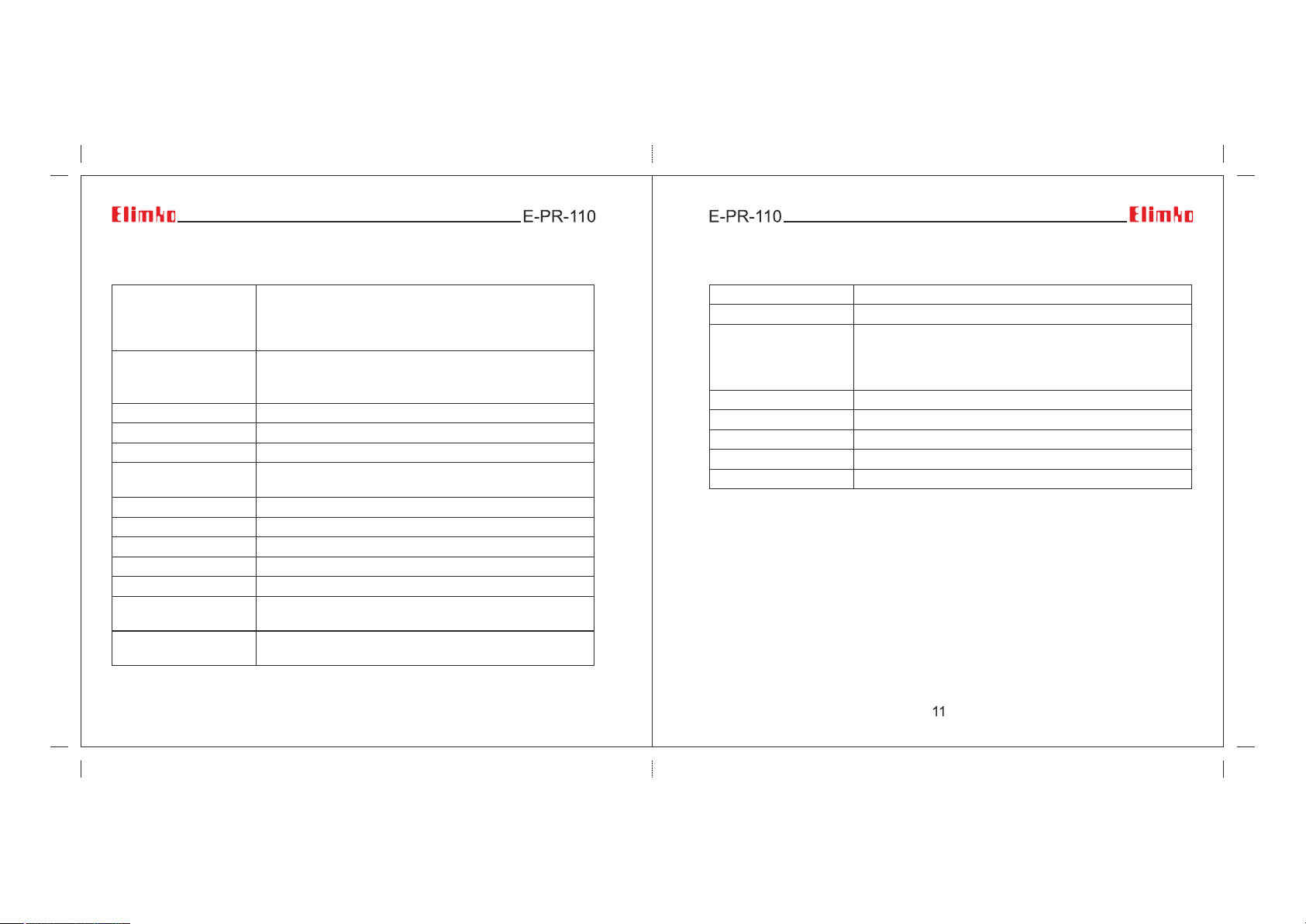
4.2 - Technical Specification
4.2 - Technical Specification
Input Types
Accuracy
Operating Voltage
Power Consumption
Data Storage Memory
Communication
Sampling Rate
Configuration Ports
Screen Type
Operating Tempreature
Storage Temperature
Analog Input
Analog Output
TC (B, E, J, K, L, N, R, S, T, U)
RT (Pt-50, Pt-100, Pt-500, Pt-1000, Ni-100, Ni-200, Ni-500,
Ni-1000)
0 ... 20 mA, 4 ... 20 mA, -2000 mV ... 2000 mV, 0 ... 10 V
TC : ±%0.5 of the reading value or ±1°C
RT : ±%0.5 of the reading value or ±1°C
Voltage / Current : ±%0.5 FS
85 - 265 V AC; 50 - 60 Hz / 85-375 V DC
30 W maximum
8 GB Micro SD Flash
10 - 100 Mbit Ethernet, RS-485, USB Host,
802.11bgn 2.4GHz Wi-Fi®
100 ms (For all channels)
Touch Panel, USB Mouse and Keyboard connections
5.7" TFT LCD, 640×480 resolution, 18 bit color, Touch panel
0°C ... 50°C
-10°C ... 85°C
Max. 24 Analog Inputs 16 bit
(1)
(isolation of channels 1000 V AC )
0 – 20 mA / 0 – 10 V can be configured.
Number of analog outputs is limited to 18
(1)
10
Digital Input
Digital Output
Max. 64 Digital Inputs
Max. 64 Digital Outputs, 24 V DC, 40 mA
(1)
(1)
Max. 18 Relay Outputs, SPST-NO; 250 V AC, 5 A
Relay Output
Mechanical Life > 10.000.000 operation
(The relay life depends on the usage configuration)
Electrical Life > 1.000.000 operation (1/10 load)
Language
Transmitter Supply
Password Protection
Protection Class
Weight
(1)
Configuration dependent. Number of analog outputs, relay outputs and transmitter
supply capacity are interdependently limited (See Section 4.1 Type Coding).
(2)
The total number of 4-20 mA transmitters to be supplied, relay outputs and analog
Turkish, English
(2)
Adjustable different authority (Max. for 5 user)
Front Panel: IP65, Rear Panel: IP20
Approx. 1.6 kg
outputs should not exceed 16 (A+B+C<=18) due to internal 24 V DC power limitation.
This limitation is valid only with the assumption of all the output will be active at the same
time.
For certain situations such as backup purposes, different output usage scenarios etc,
the number of outputs could be increased. Please contact your sales provider for advise!!!
A= Number of 4-20 mA transmitters to be supplied
B= Number of Relay Outputs (number of individual outputs, not
the number of cards, each relay output card has 6 relay outputs)
C= Number of Analog Outputs (number of individual outputs, not
the number of cards, each analog output card has 4 analog outputs)
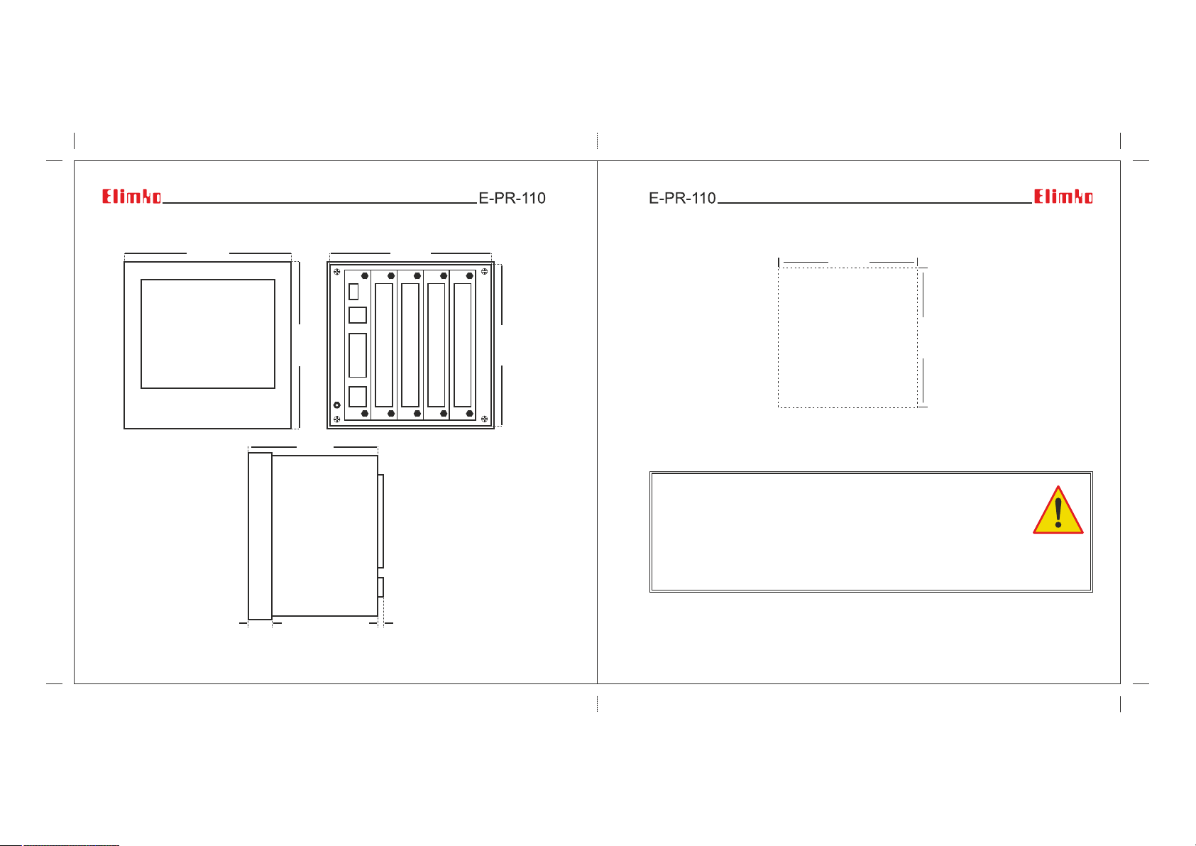
4.3 - Dimensions
144 mm
137 mm
4.4 - Panel Mounting
138 mm
Elimko
E-PR-110 Dimensions
and Panel Mounting
Figure 4.1
20 mm
144 mm
110 mm
10 mm
137 mm
Figure 4.2 E-PR-110 Panel Cut Hole
• E-PR-110 device should be installed inside a suitable grounded metal enclosure (panel).
This must prevent the live parts being accessible to human hands and metal tools.
(See Section 7. CONNECTION DIAGRAMS).
• E-PR-110 does not include a power switch. Therefore, the power supply of the
device and power outputs must be wired through the proper fuse or circuit breaker.
• To minimize the pick-up of electrical noise, the wiring of low voltage lines,
particularly the sensor input should be routed away from the high-current power cables. Where
it is not possible, use shielded cables which are grounded at both ends.
• The cables used for powering the controller and the power outputs must conform to the
standards IEC 60245 and IEC 60227.
12 13
138 mm
Panel Cut Hole
5 - USAGE
5.1 - Front Panel
5.1 - Front Panel
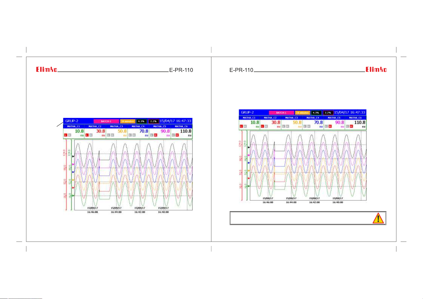
In the event of a new alarm, the background color of the title area flashes between red
and blue. After the alarms were acknowledged, the flashing ceases and the title area
appears in blue (see Figure 5.1).
Title area
Figure 5.1 Trend View
14 15
During normal operation, the operation buttons are hidden to increase
the display area. Hidden operation buttons can be made visible by touching
the bottom of the screen (see Figure 5.2). Explanations are given below
regarding the operation buttons.
Figure 5.2 Operation Keys
The capacitive touch sensor device only works with the human hand and
capacitive pens.
5.1 - Front Panel
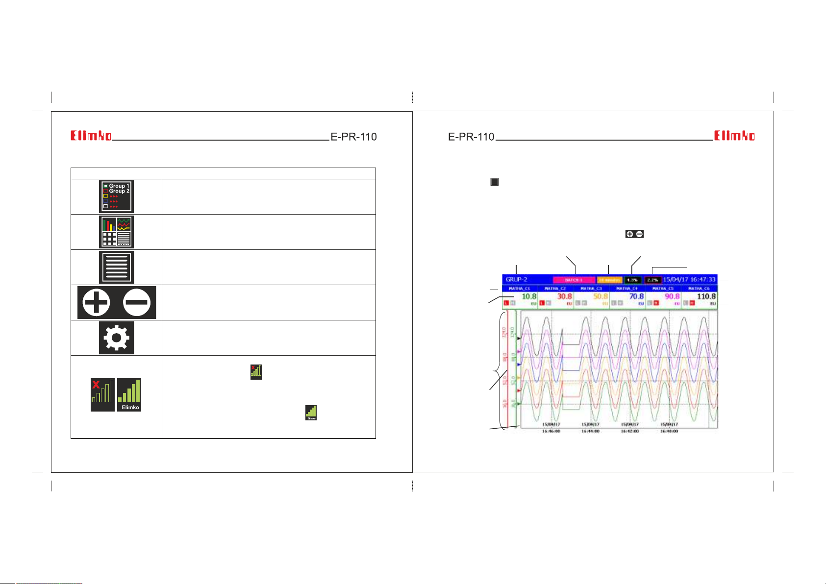
OPERATION BUTTONS
This button is used to select one of the 6 groups and
is active only TREND, BAR, DIGITAL and DIGITAL 2 views.
This button is used to select any of the TREND, BAR,
DIGITAL, OVERVIEW, ALARM LOG, TOTALIZER LOG,
INSTRUMENT LOG, OPERATOR LOG, DIGITAL LOG,
DIGITAL 2 and SCAN VIEWS options.
This button allows the operator access to the menu of
selected view. Each view has a different menu and detailed
explanations of the menus are given in the related
description of the views.
This button is active only in the trend view.
Used to increase or decrease the width of the screen.
This button allows access to the configuration pages.
5.2 - Trend Page
Traces, process values, and alarm states of the channels in selected group are viewed.
By pressing button the menu given Figure 5.5 is opened.
In Trend Page while not in History mode, newest recorded data is drawn on the screen
continuously. To view historical data, History mode should be selected in Operator Menu.
While in history mode, process values, date and time seen on the screen are the values
at the time of cursor location. By touching the screen, the location of the cursor can be
changed. While in history mode, date and time on the screen are written in red.
By Go To Date, One Grid Forward, One Grid Back, buttons, desired date and time
can be chosen.
Channel
Name
Process
Value
Group Name
Batch Name
Screen Width
Disc Storage Rate
Memory Usage
Rate
Date and
Time
Process
Unit
Figurel 5.2 Operation Buttons
Used to set up a Wi-Fi connection. If the Wi-Fi connection is
not installed, the button appears. This button is pressed
to establish a Wi-Fi connection. In the window that opens,
enter the network SSID and Password. The network
connection is established by pressing the Connect button.
If the network connection is established, the symbol
appears. Under the Wi-Fi icon, it writes the SSID of the
connected network.
16 17
Graphic
Scale
Graphic
Pen
Last Data
Figure 5.3 Trend View Screen
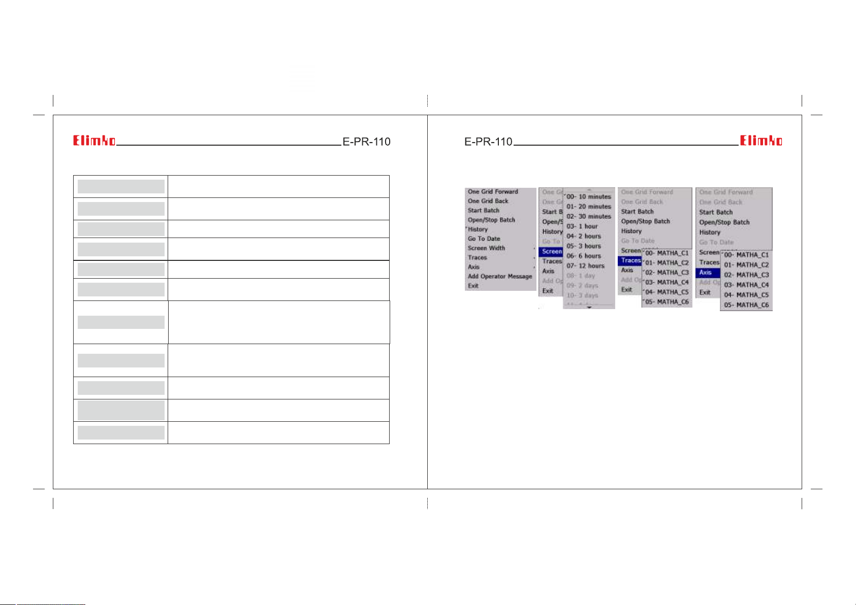
5.2 - Trend Page
5.2 - Trend Page
One Grid Forward
One Grid Back
Start Batch
Open/Stop Batch
History
Go To Date
Screen Width
Traces
Axis
Add Operator
Message
Exit
Figure 5.4 Active buttons and meaning in the Trend view screen
Historical mode must be selected for this key to be active.
This button scrolls the graph forward by a grid interval.
Historicaly mode must be selected for this key to be active.
This button scrolls the graph backwards by a grid interval.
Starts a new batch.
Opens batch management window in which user can stop
running batches and open completed batches for review.
Selects Historical mode.
While History is selected, any past date can be chosen to
review. The desired time can be entered by the keyboard.
Determines time interval that will be shown on the screen.
According to selected sampling rate, some time intervals
can appear disabled in a purpose to limit number of data
points to be displayed.
The traces that desired to be seen can be chosen with this
parameter. Desired traces can be opened or closed in
Traces Menu.
The axis of the channel to be seen on the trend can be
chosen with this parameter.
Adds operator messages. User must login in order to
reach this menu. (see Section 6. MENU PAGES)
Used to exit the screen. The same operation can be
performed by touching an empty area on the screen.
18 19
Figure 5.5 Active buttons and options on the Trend view screen
5.2 - Trend Page
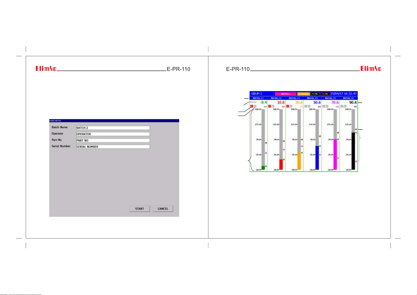
Recording can be made continuously or batch base. To start a batch in any time,
Start Batch is selected in Operator Menu. Start Batch screen will be opened as
shown below. In this screen Batch Name, Operator, Part No and Serial No can be
filled to any values depending on batch process and Start is selected. When the batch
starts, Batch Name is written on the top of Trend Page. Stop Batch command in
Operator Menu provide access to manage running and recorded batches. Start/Stop
batch operations can also be performed with a barcode reader. (see Appendix 4)
Figure 5.6 Start Batch Screen
20 21
5.3 - Bar Graphic Page
Channel
Name
Process
Value
Alarm 1
Alarm 2
If the alarms are
defined, H or L
is written
according to
alarm types.
Active alarms
are shown with
red color.
Scale
Figure 5.7 Bar View Screen
In Bar Graphic Page, bar graphics, process values, and alarm states of
6 channels in selected group are viewed.
Process
Unit
Process
Value
Alarm Set
Points
The set points
of Alarm1 and
Alarm2.
The set points
of Alarm1 and
Alarm2 are
shown with
purple and
claret red
respectively.
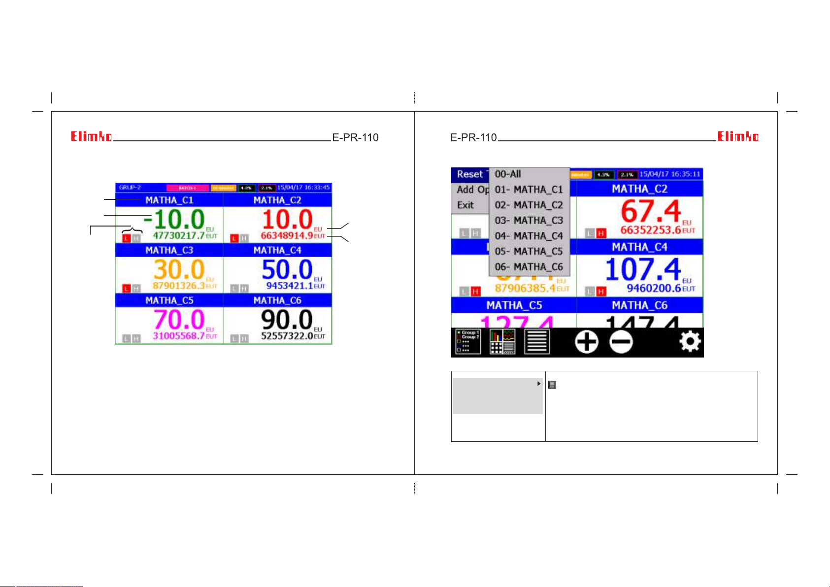
5.4 - Digital View Page
Channel
Name
Process
Value
Alarm
States
Figure 5.8 Digital View Screen
In Digital View Page, totalizer values, process values, and alarm states of
6 channels in selected group are viewed.
22 23
Process
Unit
Totalizer
and Unit
5.4 - Digital View Page
Figure 5.9 Totalizer reset and add operator messages (Digital View Page)
Reset Totalizer
Add Operator Message
Exit
Operator Menu for Digital View Page is opened by pressing
button. To reset the totalizer of an individual source,
select the corresponing source name in sub menus of
Reset Totalizer menu. To reset the totalizers of all sources
in selected group, All can be selected.
Add Operator Message: Adds a operator message. It is
only active when the user is logged in.
(See Section 6. MENU PAGES).
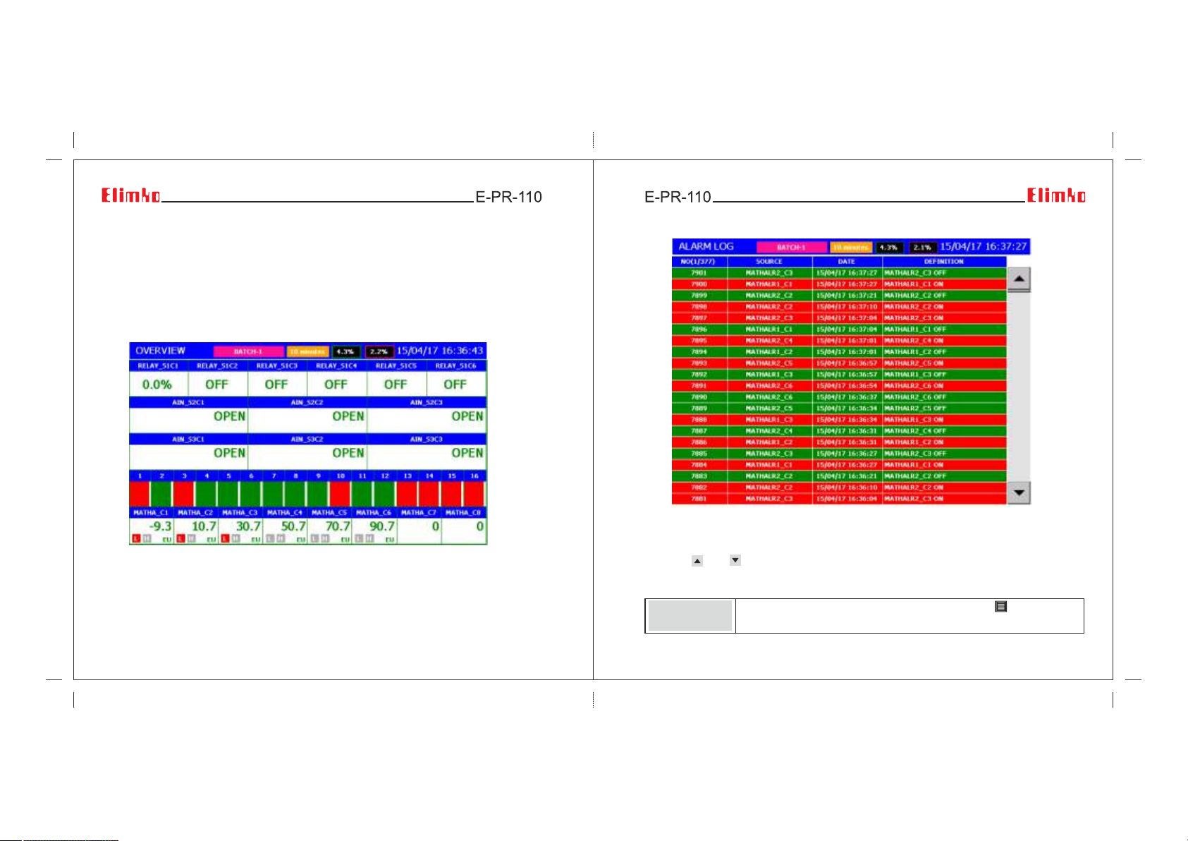
5.5 - Overview Page
All channels can be viewed in this page together. Process values of all available sources
can be viewed in a single page. Each row in the page corresponds to a process group
from one of the available slots, Modbus Channels or Math Analog Channels. Empty slots
and undefined MATH and MODBUS channels are not shown. Analog process groups
having more than 8 channels occupy two rows and due to overall row limitation, some
of the process groups appears intermittently.
Figure 5.10 Batch Screen View
5.6 - Alarm Log
Figure 5.11 Alarm Log screen
The last occurred and released 10000 alarms with date and definitions are listed in
Alarm Page. The latest alarm is on the top of the list. The list can be scrolled by
pressing and buttons. Active alarms are shown in red color and released
alarms are shown in green color. Active alarms which appear in red turn green after
the alarms were acknowledged by selecting Acknowledge Alarms parameter.
Acknowledge
Exit
Operator Menu for Alarm Page can be opened with button. Alarms
are acknowledged with selecting Acknowledge Alarms parameter.
24 25
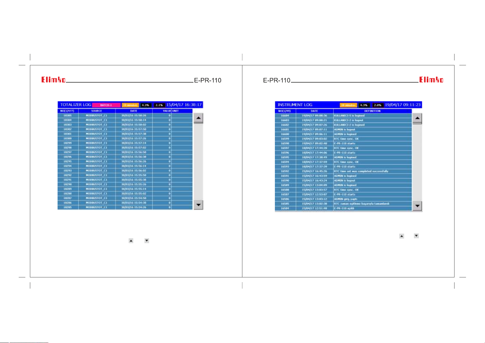
5.7 - Totalizer Log
5.8 - Instrument Log
Figure 5.12 Totalizer Log screen
Source Name, record date, totalizer value and unit of the last recorded 10000 totalizer
values are listed in Totalizer Page. The last recorded totalizer is displayed at the top of
the list. Totalizer values can be scrolled by and buttons. The time intervals of
totalizers are defined with the Logging Source parameter of related Totalizer.
26 27
Figure 5.13 Instrument Log screen
The date and definition of last recorded 1000 events of the device are listed in
Instrument Log Page. The last recorded event appears on the top. and buttons
are used to scroll the list up or down.
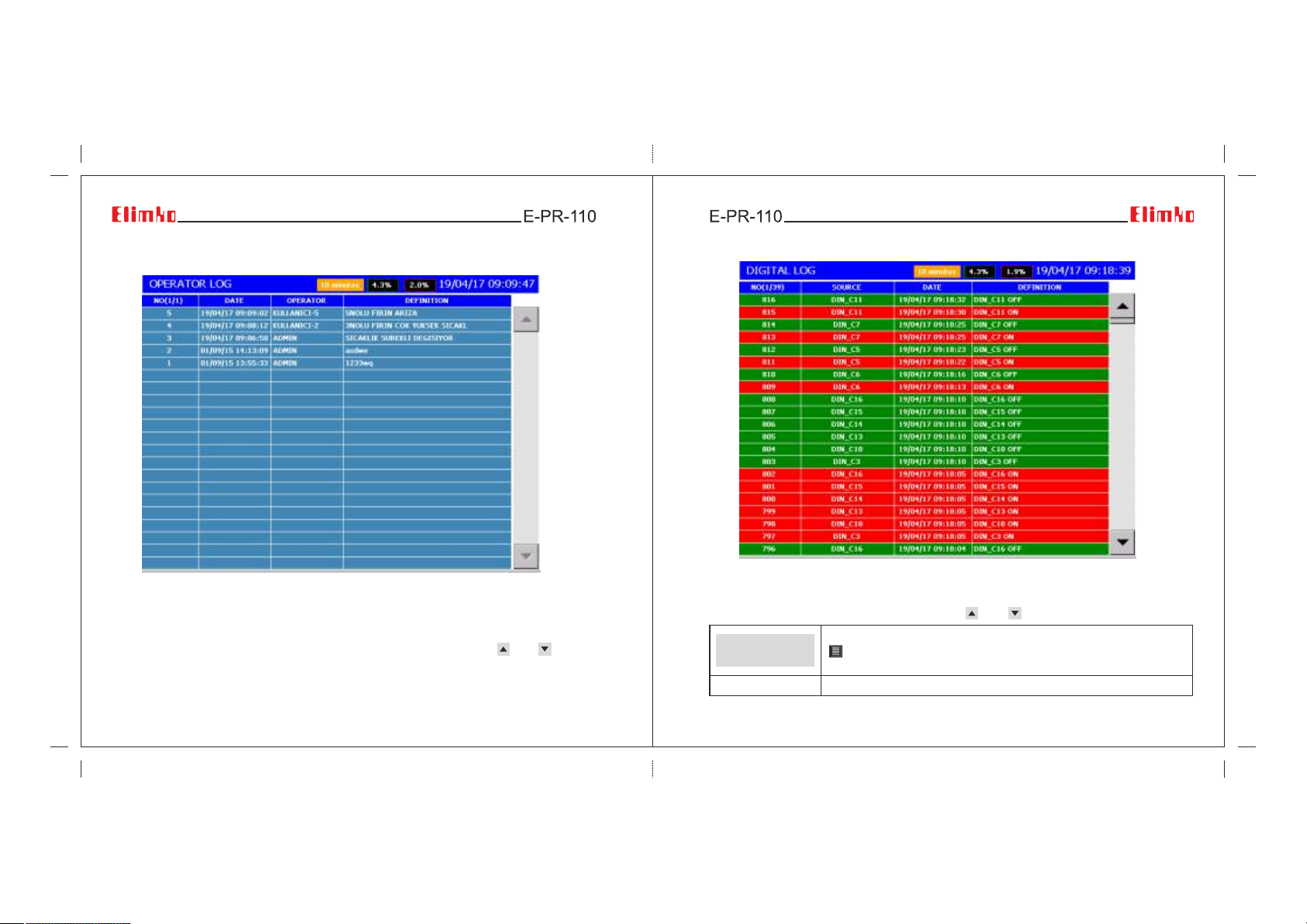
5.9 - Operator Log
Figure 5.14 Operator Log screen
Operators can add messages anytime while operating the device in order to assert
certain events and information. In order to add messages, the operator must login first
and should press Add Operator Message menu in the Operator Menu. Operator
message with descending date order are listed in Operator Log Page. and keys
scrolls the page up and down direction (see Section 5.2 TREND PAGE and
5.4 DIGITAL VIEW PAGE).
28 29
5.10 - Digital Log
Figure 5.15 Digital Log screen
Source Name, record date and definition of the last recorded 65536 digital log values
are listed in Digital Log Page. The last recorded digital log value is displayed at the top
of the list. Digital log values can be scrolled by and buttons.
Acknowledge
Exit
Operator Menu for Digital Log Page can be opened by pressing
button. Alarms are acknowledged by selecting
Acknowledge digital logs menu.
Note: In "NO(X/Y) column, X is page number and Y is number of pages.
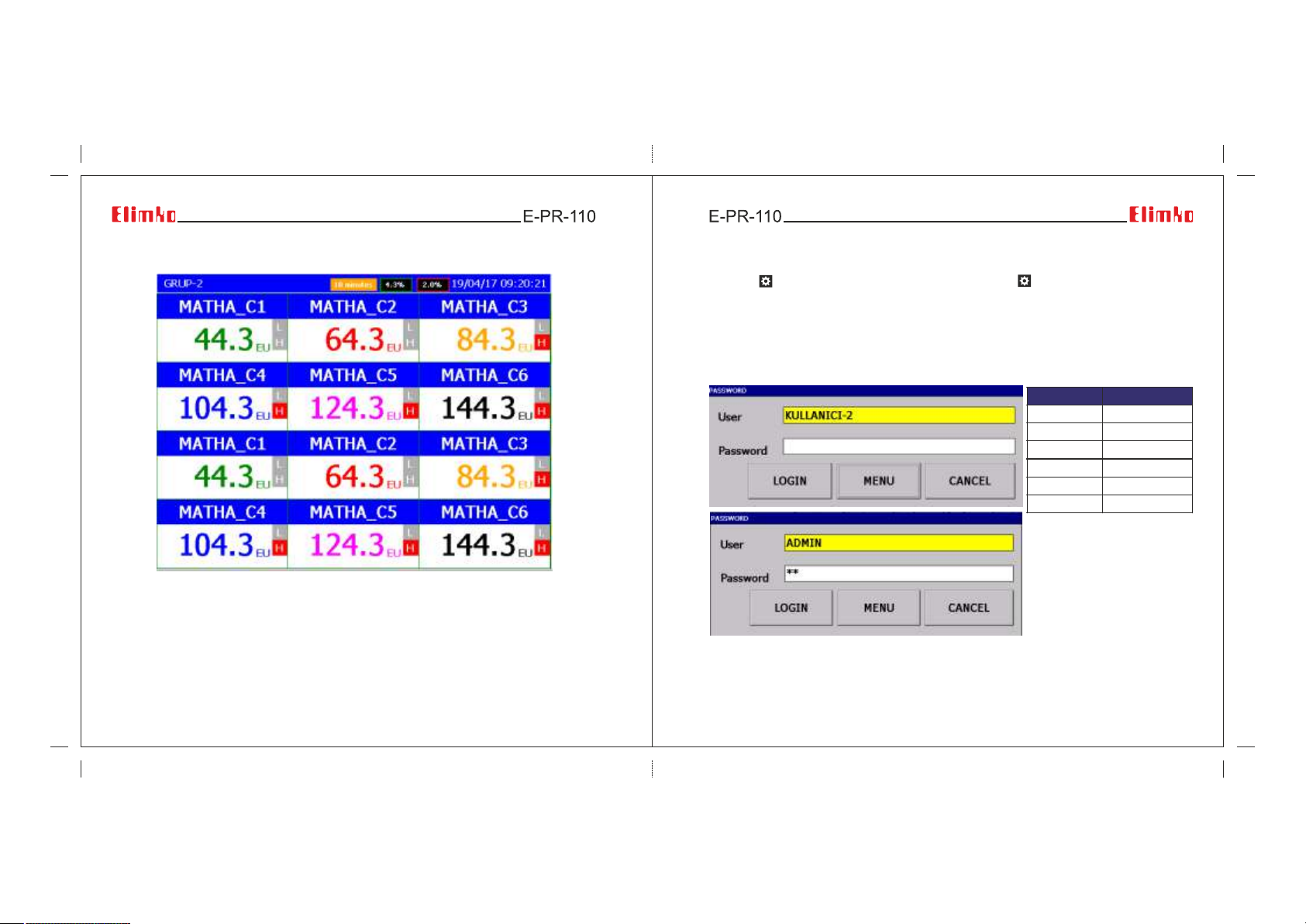
5.11 - Digital 2
6 - MENU PAGES
Pressing key accesses to Menu page. Upon pressing key authentication window
opens and user name/ password are asked. After selecting UserName and Password,
main menu is reached by either pressing MENU or LOGIN button. LOGIN access does
not require authentication on subsequent entries until LOGOUT is pressed from Main
Menu. Depending on previously defined authorization rights, some of the sub menus
may appear disabled (see Section 6.4. Security). Default values for the user password
are given:
Figure 5.16 Digital 2 screen
Two consecutive groups (selected group and the following group which may wrap to first
or last group depending on selected group) can be viewed digitally on the same page.
30 31
Figure 6.1 Password input window to the main menu
USERS
ADMIN
USER 2
USER 3
USER 4
USER 5
USER 6
PASSWORD
10
02
03
04
05
06
 Loading...