

Elimko E-70-O User Manual
E-70-Ö DIGITAL CONTROLLER USER MANUAL
Elimko
m
The package of E-70-Ö controller contains; Controller, 2 pieces of mounting clamps, User manual and Guarantee certificate
m
After opening the package, please check the contents with the above list. If the delivered product is wrong type, any item is
missing or there are visible defects, contact the vendor from which you purchased the product.
E-70-Ö controller is designed for panel mounting and should be used in an industrial environment.
m
Before installing and operating the controller, please read the user manual thoroughly.
m
The installation and configuration of the controller must only be performed by a person qualified in instrumentation.
m
Keep the unit away from flamable gases, that could cause explotions.
m
Do not use alcohol or other solvents to clean the controller. Use a clean cloth soaked in water tightly squeezed to gently wipe the outer
surface of the controller.
m
The product life of this instrument is 10 years.
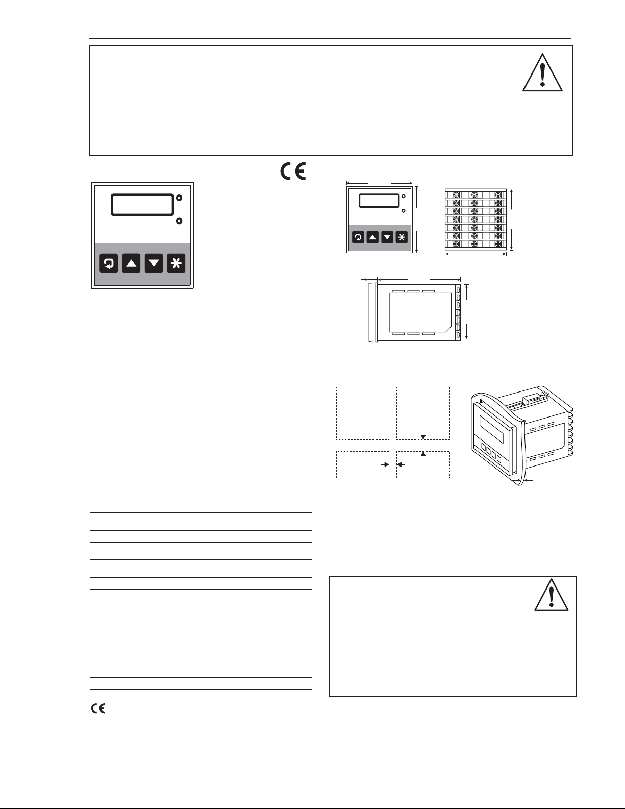
1. DESCRIPTION
ALM
ECO
22 C°
3. DIMENSIONS
67 mm
67 mm
72 mm
72 mm
10 mm
100 mm
67 mm
ALM
ECO
q
This controller complies with the European Low Voltage
Directive 73/23/EEC, by the application of safety standard
TS 2418 EN 61010-1. (Pollution degree 2)
q
This controller complies with the EMC Directive 89/336/EEC,
by the application of EMC standard TS EN 61326.
2. TECHNICAL SPECIFICATIONS
Resistance Thermometer (Pt-100)
4 digit 10 mm 7 segment led display
24 V AC ± %10; 50-60 Hz
2.5 W (4 VA)
±0.5% of the reading value or ±2 C)
±1 digit max.
o
16 bit
>1 000 000 operations (under 1/10 of load)
EEPROM (100.000 max. write-erase)
0 C, +55 C
(with no condensation or icing)
oo
-25 C, +65 C
(with no condensation or icing)
oo
Front Panel : IP 66 (
Rear Case : IP 20
NEMA 4X)
380 g
Input Type
Alarm Outputs
Display Type
Accuracy
Analog Digital
Converter
Operating Voltage
Power Consumption
Protection Class
Operating
Temperature
Storage Temperature
Relay Mechanical Life
Memory
Weight
Relay Electrical Life
10 000 000 operations
Relay 2: SPDT-NO-C-NC 250 V AC, 5A
Relay 1: SPST-NO 250 V AC, 5A
q
q
q
q
Cut a hole in the panel. (See the figure for overall dimensions.)
Slide the controller into the cutout from the front of the panel.
Fit the mounting clamps to the controller, ensuring the lugs are
located in their slots.
Fasten the mounting clamps using the retaining screws.
The cables used for powering the controller and the power outputs
must conform to the standarts IEC 60245 and IEC 60227.
m
To minimize the pick-up of electrical noise, the wiring of low voltage
lines, particularly the sensor input should be routed away from the
high-current power cables. Where it is not possible, use shielded
cables with the shield grounded at both ends.
m
E-70-Ö controller does not include a power switch. Therefore, the
power supply to the controller and power outputs must be wired
through the proper fuse or circuit breaker.
m
E-70-Ö controller should be installed inside a suitable
grounded metal enclosure (panel). This must prevent
the live parts being accessible to human hands and
metal tools.
m
4. PANEL MOUNTING
min.35 mm
min.10 mm
+0.7
-0.0
68x68mm
max. 15 mm
Panel Cutout and
Minimum Spacing
E-70-Ö digital controller
measures its input temperature
by means of a Pt-100 resistance
thermometer and controls two
output relays as a function of the
input temperature and the state
of internal timers. The control of
RL1 and RL2 output relays are
as follows;
RL1: When the device is energized, the output relay RL1 is
activated. When the measured temperature decreases and
becomes equal to SETL (2°C), 10 minutes timing will be started.
During the timing period, RL1 will be active and measured
temperature has no effect on the state of RL1. When the time is
out, RL1 becomes inactive, provided that the measured temperature
is less than SETH (10°C). When the temperature increases and
reaches SETH, RL1 becomes active again and the same steps will
be repeated. The state of RL1 is indicated by the green led ECO,
this led is illuminated while RL1 is inactive.
RL2: Applying the operating voltage to the controller starts 20
minute timer. Initially the output relay RL2 is de-energized. During
the timing period, RL2 will be inactive and measured temperature
has no effect on the state of RL2. When timing expires, the state of
RL2 is controlled by the input temperature. When the temperature
is between ASTL (0°C) and ASTH (15°C), RL2 will be inactive. If
the measured temperature is greater than ASTH or less than ASTL,
RL2 will be energized. ALM led (red) on the front panel will be
flashed while RL2 is energized.
E-70-Ö is housed in a 72 x 72 mm plastic case conforming IEC
668 standard. The operating voltage of the device is 24 V AC
±%10, 50-60 Hz.

E-70-Ö DIGITAL CONTROLLER USER MANUAL
5. CONNECTION DIAGRAM
Before operating the controller, ensure that the controller
is correctly configured. Incorrect configuration could
result in damage to the process being controlled.
m
The terminals 01 to 07 are electrically live. While the
instrument is powered, never touch to these terminals.
m
The labels on the sides of the controller identify the ordering
code (Type), serial number and wiring connections.
Connection diagram is given below.
Manufacturer / Technical Support:
Elimko Co. Ltd. 8. cadde 68. Sokak No:16 06510 Emek - ANKARA / TURKEY
Phone:+ 90 312 212 64 50 Fax:+ 90 312 212 41 43 www.elimko.com.tr e-mail:elimko@elimko.com.tr
KY-70-1209-0-Ö
The front panel view of the E-70-Ö controller is given in
section. In normal operation, the four digit display displays the process
value and unit. The display of the controller displays between -19 and 99.
Out of this range or while the connection of the sensor is broken the
display will be shown as ( )
1. DESCRIPTION
--
6. OPERATION
The other parameters are configured in configuration mode.
q
In order to access the configuration mode, and buttons must be
pressed simultaneously.
CD
q
Just after this operation, message is displayed for one second
duration, is displayed in the display. The security code must be
entered with and buttons in order to access the parameters.
COD
0
AF
q
The entered security code must be correct, otherwise pressing
button will revert to normal operation.
D
q
The factory setting value of security code is “10”. The security code is
defined by parameter; user can edit this parameter to define a new
security code. If the value of security code is forgotten, pressing and
buttons simultaneously at least 10 seconds, makes possible to access
the parameters.
PAS
C
D
q
If the entered security code is correct, pressing key will select the
first parameter.
C
q
While a parameter is selected, the parameter value is edited by and
buttons.
Pressing button will select the next parameter.
Pressing button exist the configuration mode.
F
A
C
D
16
15
18
19
20
PT-100
02
21
17
04
03
01
06
07
3A
250
VAC
3A
250
VAC
05
24 V AC; 50-60Hz24 V AC; 50-60Hz
RL1
3A
250
VAC
3A
250
VAC
RL2
7. EXPLANATION OF PARAMETERS
21 C*
ASTL
0C*
SETL
2*C
Code ok. Code wrong
COD
0
SETH
SFT
0*C
10*C
UNT
PAS
10
0
ASTH
10*C
COD:Security code is asked with this parameter. It can be
adjusted between -1999 and 9999.
SFT
:
Defines the shift value of the input. It can be adjusted
between -10°C and 10°C. The value of input that seen
on the display is the sum of measured value and
parameter.
SFT
UNT : Indicates the measuring unit of the input. It can be
adjusted as 0 (°C) or 1 (°F). If parameter is changed,
, , , , and parameters should be
revised. Also the adjustment limits of set points are depend
on this parameter.
UNT
ASTL ASTH SETL SETH SFT
PAS:Define the security code. Parameter can be adjusted
between -1999 and 9999.
ASTL:The low value of alarm set point. This parameter is
used for controlling Relay 2.
ASTH
:
The high value of alarm set point. This parameter is
used for controlling Relay 2.
SETL
:
The low value of control set point. This parameter is
used for controlling Relay 1.
SETH
:
The high value of control set point. This parameter is
used for controlling Relay 1.
 Loading...