

Page 1
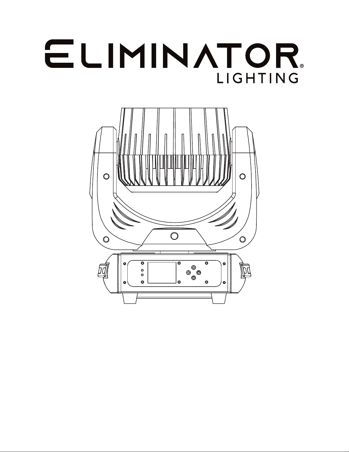
STRYKER WASH
User Manual
Page 2
©2023 Eliminator Lighting all rights reserved. Information, specications, diagrams, images, and
instructions herein are subject to change without notice. Eliminator Lighting logo and identifying product names and numbers herein are trademarks of ADJ Products, LLC. Copyright protection claimed
includes all forms and matters of copyrightable materials and information now allowed by statutory or
judicial law or hereinafter granted. Product names used in this document may be trademarks or registered trademarks of their respective companies and are hereby acknowledged. All non-Eliminator
brands and product names are trademarks or registered trademarks of their respective companies.
Eliminator Lighting and all afliated companies hereby disclaim any and all liabilities for property,
equipment, building, and electrical damages, injuries to any persons, and direct or indirect economic
loss associated with the use or reliance of any information contained within this document, and/or as
a result of the improper, unsafe, insufcient and negligent assembly, installation, rigging, and operation of this product.
DOCUMENT VERSION
Due to additional product features and/or enhancements, an updated version of
this document may be available online.
Please check www.adj.com for the latest revision/update of this manual
before beginning installation and/or programming.
Date
01/17/2023 1.0 1.0 13 / 23 Ch. Initial Release
02/14/2023 1.1 N/C No Change
02/24/2023 1.2 N/C No Change
05/11/2023 1.3 N/C No Change Add FCC Information
07/17/2023 1.4 N/C No Change
Europe Energy Saving Notice
Energy Saving Matters (EuP 2009/125/EC)
Saving electric energy is a key to help protecting the enviroment. Please turn off all electrical products when
they are not in use. To avoid power consumption in idle mode, disconnect all electrical equipment from power
when not in use. Thank you!
Document
Version
Software
Version
DMX Channels Notes
Updated Control Panel, System Menu,
DMX Traits, Specifications.
Updated Introduction, Features,
Specifications
Updated Dimensional Drawings,
Specifications
2
Page 3

TABLE OF CONTENTS
Introduction 4
Limited Warranty (USA Only) | Warranty Registration 5
Features 6
Safety Precautions 7
Overview 8
Installation 9
Control Panel 13
System Menu 14
DMX Set Up 17
DMX Traits 19
Primary-Secondary Set Up | Power Linking 21
Maintenance Guidelines 22
Dimensional Drawings 23
Specifications 24
FCC Information 25
3
Page 4

INTRODUCTION
Unpacking: Thank you for purchasing the Stryker Wash. Every device has been thoroughly tested and
has been shipped in perfect operating condition. Carefully check the shipping carton for damage that
may have occurred during shipping. If the carton appears to have been damaged, carefully inspect your
xture for any damage and be sure all accessories necessary to operate the unit have arrived intact.
In the event that damage has been found or parts are missing, please contact our toll free customer
support number for further instructions. Do not return this unit to your dealer without rst contacting
customer support.
Introduction: The Stryker Wash is a DMX-capable, LED-powered moving head xture. It features mul-
tiple selectable DMX channel modes, pan and tilt control, RGBW color, zoom adjustment, and strobe
effects.
Customer Support: Contact Eliminator Service for any product related service and support needs. Also
visit forums.adj.com with questions, comments or suggestions.
Parts: To purchase parts online visit:
http://parts.adj.com (US)
http://www.adjparts.eu (EU)
ELIMINATOR SERVICE USA - Monday - Friday 8:00am to 4:30pm PST
Voice: 800-322-6337 | Fax: 323-582-2941 | [email protected]
ELIMINATOR SERVICE EUROPE - Monday - Friday 08:30 to 17:00 CET
Voice: +31 45 546 85 60 | Fax: +31 45 546 85 96 | [email protected]
ELIMINATOR LIGHTING USA
6122 S. Eastern Ave. Los Angeles, CA. 90040
323-582-2650 | Fax 323-532-2941 | www.adj.com | [email protected]
ADJ SUPPLY Europe B.V
Junostraat 2 6468 EW Kerkrade, The Netherlands
+31 (0)45 546 85 00 | Fax +31 45 546 85 99
www.americandj.eu | [email protected]
ADJ PRODUCTS GROUP Mexico
AV Santa Ana 30 Parque Industrial Lerma, Lerma, Mexico 52000
+52 (728) 282-7070
CAUTION! This device is intended for indoor use only! Do not expose to rain or moisture!
CAUTION! There are no user serviceable parts inside this unit. Do not attempt any repairs yourself,
as doing so will void your manufacturer’s warranty. In the unlikely event your unit may require service,
please contact Eliminator Lighting.
Do not discard the shipping cartoon in the trash. Please recycle when ever possible.
4
Page 5

LIMITED WARRANTY (USA ONLY)
1 Year Limited Warranty: The Eliminator Lighting warranty is valid for 1 year from the date of purchase. Our
1 year limited warranty covers manufacturing defects only. The serial number of your device and the place of
purchase with dated valid receipt must be submitted at time of service. The Eliminator Lighting warranty does
not cover items or parts prone to wear and tear: lamps, fuses, brushes and belts. Eliminator Lighting warranty
is only valid within the United States.
To register your Eliminator Lighting product online, please click here to the ADJ Warranty Registration Page:
https://www.adj.com/portal/user/register/
WARRANTY REGISTRATION
Please fill out the enclosed warranty card to validate your purchase. All returned service items,
whether under warranty or not, must be freight pre-paid and accompanied by a return authorization
(R.A.) number. The R.A. number must be clearly written on the outside of the return package. A brief
description of the problem as well as the R.A. number must also be written down on a piece of paper
included in the shipping carton. If the unit is under warranty, you must provide a copy of your proof of
purchase invoice. You may obtain an R.A. number by contacting our customer support team. All packages returned to the service department not displaying an R.A. number on the outside of the package
will be returned to the shipper.
5
Page 6

FEATURES
• 19 x 12W high power RGBW 4-in-1 LED
• Fast, precise pan & tilt movements
• Three zone DMX control mode
• Primary / Secondary stand alone mode
• Motorized zoom: 6 ~ 50°
• Linear CT DMX control channel: 3200K - 10000K
• Up to 18 strobe flashes per second
INCLUDED ITEMS
• Power Cable (x1)
• Omega Bracket (x1)
6
Page 7
SAFETY PRECAUTIONS
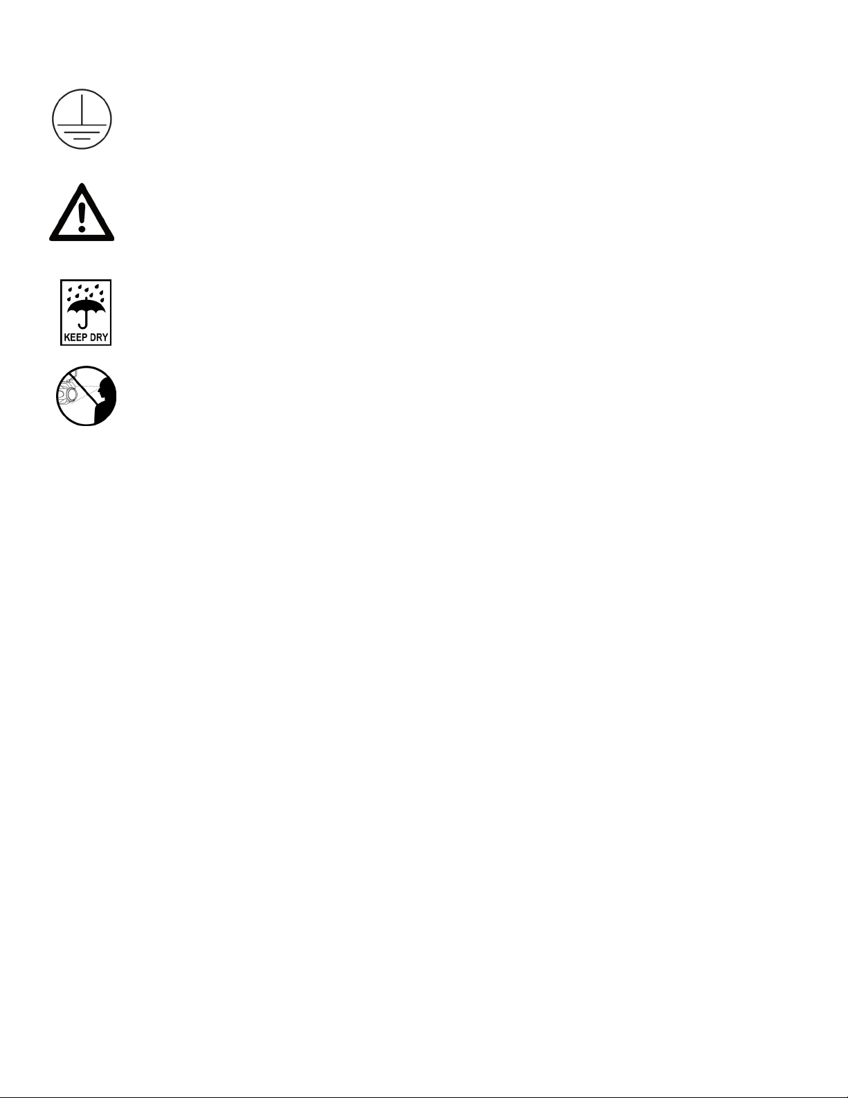
PROTECTION CLASS 1 - FIXTURE MUST BE PROPERLY GROUNDED.
THERE ARE NO USER SERVICEABLE PARTS INSIDE THIS UNIT. DO NOT ATTEMPT
ANY REPAIRS YOURSELF, AS DOING SO WILL VOID YOUR MANUFACTURER’S
WARRANTY. DAMAGES RESULTING FROM MODIFICATIONS TO THIS FIXTURE
AND/OR THE DISREGARD OF SAFETY INSTRUCTIONS AND GUIDELINES IN THIS
MANUAL VOID THE MANUFACTURER’S WARRANTY AND ARE NOT SUBJECT TO
ANY WARRANTY CLAIMS AND/OR REPAIRS.
INDOOR USE ONLY! DO NOT EXPOSE TO RAIN OR MOISTURE!
NEVER LOOK DIRECTLY INTO THE LIGHT SOURCE!
RETINA INJURY RISK - MAY INDUCE BLINDNESS!
SENSITIVE PERSONS MAY SUFFER AN EPILEPTIC SHOCK!
• Ambient operating temperature range is 5° F to 104° F (-15° C to 40° C)!
• DO NOT TOUCH the fixture housing during operation. Disconnect the power and allow approximately
15 minutes for the fixture to cool down before servicing.
• DO NOT shake the fixture, and avoid brute force when installing and/or operating the fixture.
• DO NOT operate the fixture if the power cord has become frayed, crimped and/or damaged. If the
power cord is damaged, replace immediately with a new one of the same power rating.
• DO NOT attempt to remove or break off the ground prong from the electrical cord. This prong is used
to reduce the risk of electrical shock and fire in the event of an internal short.
• DO NOT attempt to operate this unit if it has been damaged in any way.
• DO NOT spill water or other liquids into or on to your unit.
• Disconnect from main power before making any type of connection.
• DO NOT block any air ventilation slots. All fan and air inlets must remain clean and never blocked.
Allow approx. 20” (50cm) between fixture and other devices or a wall for proper cooling.
• Always be sure to mount this unit in an area that will allow proper ventilation. Allow about 20” (50cm)
between this device and a wall.
• DO NOT remove the cover for any reason.
• When installing fixture in a suspended enviroment, always use mounting hardware that is no less than
M10 x 25mm, and always install fixture with an appropriately rated safety cable.
• Never plug this unit in to a dimmer pack.
• During long periods of non-use, disconnect the unit’s main power.
• Always mount this unit in safe and stable matter.
• Power-supply cords should be routed so that they are not likely to be walked on or pinched by items
placed upon or against them, paying particular attention to the point where they exit from the unit.
• Cleaning - The fixture should be cleaned only as recommended by the manufacturer.
• Heat - The appliance should be situated away from heat sources such as radiators, heat registers,
stoves, or other appliances (including amplifiers) that produce heat.
• The fixture should be serviced by qualified service personnel when:
A. The power-supply cord or the plug have been damaged.
B. Objects have fallen onto, or liquid has been spilled into, the fixture.
C. The fixture does not appear to operate normally or exhibits a marked change in performance.
D. The fixture has fallen and/or has been subjected to extreme handling.
7
Page 8
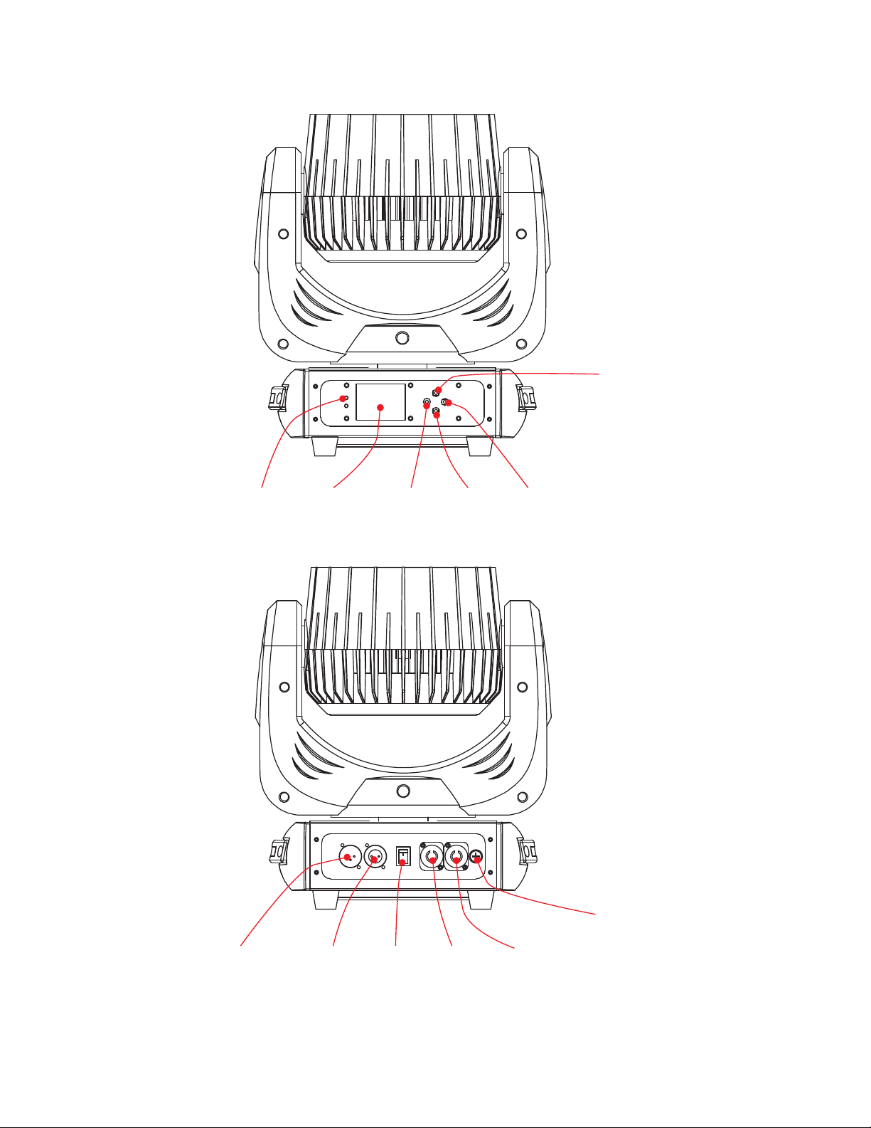
OVERVIEW
Up
Button
DMX
LED
Display
Screen
Menu
Button
Down
Button
Enter
Button
DMX
Input
DMX
Output
Power
Switch
Power
Input
8
Fuse
Power
Output
Page 9

INSTALLATION
DO NOT INSTALL THE FIXTURE IF YOU ARE NOT QUALIFIED TO DO SO!
Fixture MUST be installed following all local, national, and country commercial electrical and construction codes and regulations.
When installing the unit, the trussing or area of installation must be able to hold at least 10 times the
weight of the unit and any attached accessories without any deformation. The unit must be secured
with a secondary safety attachment, e.g. an appropriately-rated safety cable.
Before rigging/mounting a single fixture to any metal truss/structure or placing the fixture(s) on any
surface, a professional equipment installer MUST be consulted to determine if the metal truss/structure
or surface is properly certified to safely hold the combined weight of the fixture(s), clamps, cables, and
accessories.
Ambient operating temperature range is 5°F to 104°F (-15°C to 40°C).
Fixture(s) should be installed away from walking paths, seating areas, or areas where unauthorized
personnel might reach the fixture by hand.
NEVER stand directly below the fixture(s) when rigging, removing, or servicing.
Overhead fixture installation must always be secured with a secondary safety attachment, such as an
appropriately rated safety cable that can hold at least 10 times the weight of the fixture.
Overhead mounting requires extensive experience, including calculating working load limits, knowl-
edge of installation material being used, and perodic safety inspection of all installation material as
well as the unit itself. If you lack these qualifications, do not attempt the installation yourself.
The installation should be checked by a skilled person once a year.
9
Page 10
INSTALLATION
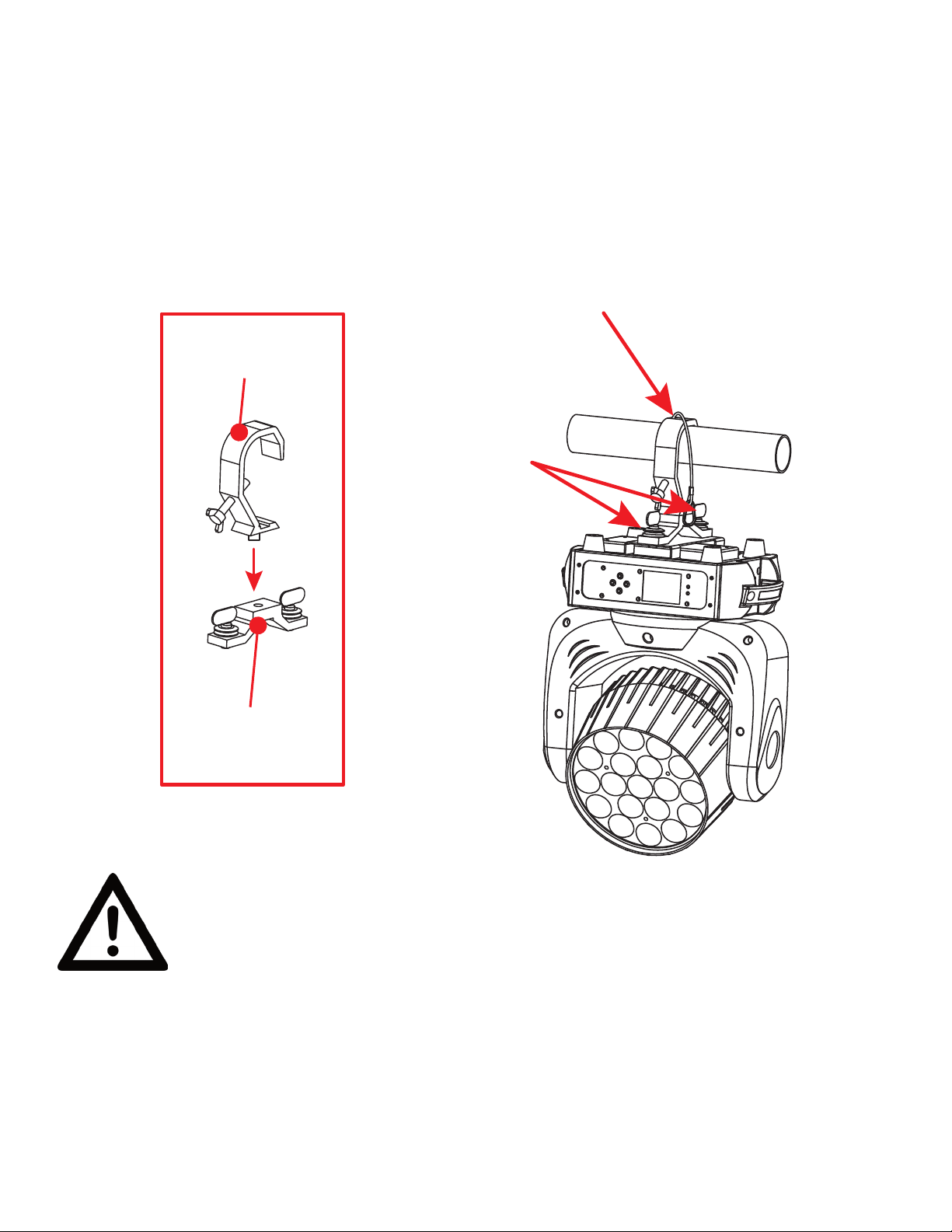
CLAMP MOUNTING
Use an appropriately rated nut and bolt to attach the mounting clamp (not included) to the Omega
bracket. This fixture features attachment points for an Omega on the bottom surface of the unit.
Insert the Omega bracket into these mounting points, then turn the quick-lock fasteners to secure the
Omega bracket to the fixture. Additionally, a SAFETY CABLE of the appropriate weight rating should
be looped under the fixture’s Omega bracket attachment plate, then over the truss. Refer to the illus-
tration below:
SAFETY
CABLE
MOUNTING
CLAMP
OMEGA
BRACKET
ATTACHMENT
POINTS
OMEGA
BRACKET
SAFETY CABLE:
ALWAYS ATTACH A SAFETY CABLE WHENEVER INSTALLING THIS FIXTURE
IN A SUSPENDED ENVIRONMENT TO ENSURE THAT THE FIXTURE WILL NOT
FALL IF THE CLAMP FAILS.
NOTICE: Ambient operational temperature range for this lighting fixture is 5˚ F to 104˚ F (-15˚ C to
40˚ C). Do not place this lighting fixture in an environment where the temperatures fall outside this
range. This will allow the fixture to run at its best and help prolong the fixture life.
10
Page 11
INSTALLATION
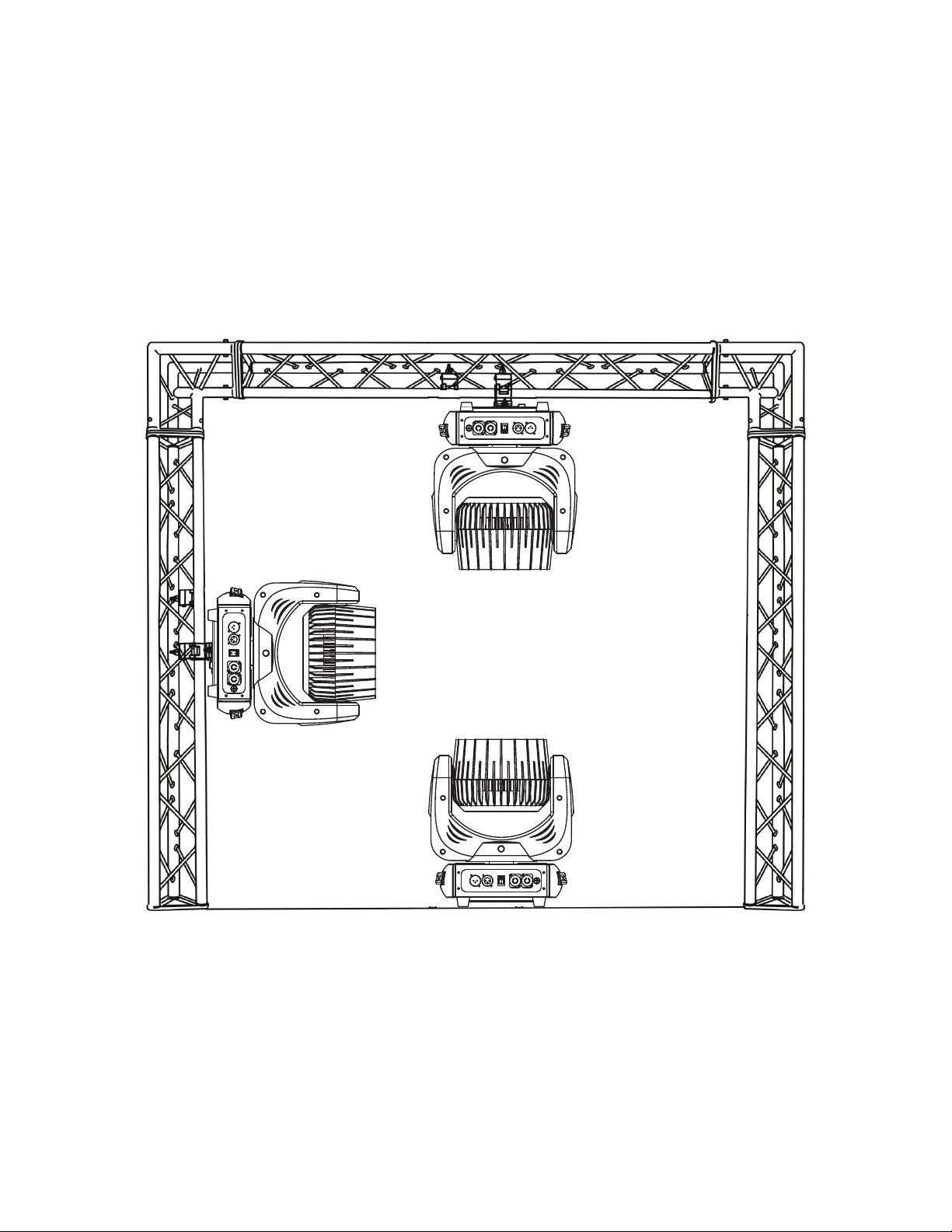
RIGGING ORIENTATIONS
Overhead rigging requires extensive experience, including calculating working load limits, installation
material being used, and periodic safety inspection of all installation material and the fixture, among
other skills. If you lack these qualifications, do not attempt the installation yourself. Improper installation
can result in bodily injury.
The fixture is fully operational in the following positions: hanging from a horizontal truss, suspended
sideways from a vertical truss, or standing upright on a flat, level surface. See the illustration below for
reference.
11
Page 12
INSTALLATION
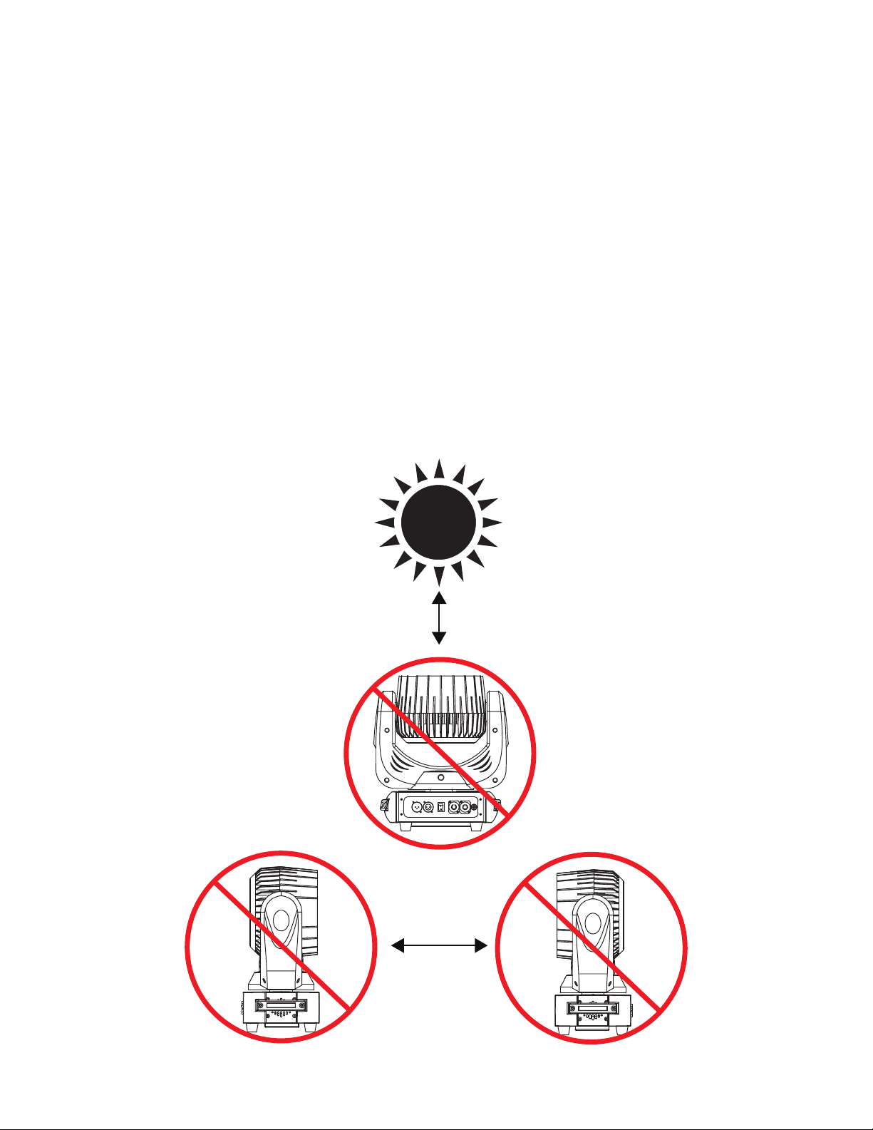
POTENTIAL INTERNAL FIXTURE DAMAGE FROM EXTERNAL SOURCES OF LIGHT BEAMS
External sources of light beams from direct sunlight, lighting and moving head fixtures, and lasers,
which are focused directly towards the exterior housing and/or penetrate the front lens opening of
Eliminator lighting fixtures, can cause severe internal damage including burning of optics, dichroic color
filters, glass and metal gobos, prisms, animation wheels, frost filters, iris, shutters, motors, belts, wiring, discharge lamps, and LEDs.
This issue is not specific only to Eliminator lighting fixtures, but rather it is a common issue with lighting
fixtures from all manufacturers. Although there is no true way to fully prevent this issue from happen-
ing, the guidelines below can reduce the risk of potential damage. Contact Eliminator Service for more
details.
DO NOT EXPOSE THE FIXTURE AND/OR FRONT LENS OPENING TO LIGHT BEAMS FROM
DIRECT SUNLIGHT, OTHER LIGHTING OR MOVING HEAD FIXTURES, AND LASERS DURING
UNPACKING, INSTALLATION, USE, AND EXTENDED IDLE TIMES OUTDOORS. DO NOT FOCUS
A LIGHT BEAM FROM ONE LIGHTING FIXTURE DIRECTLY TOWARDS ANOTHER.
12
Page 13
CONTROL PANEL
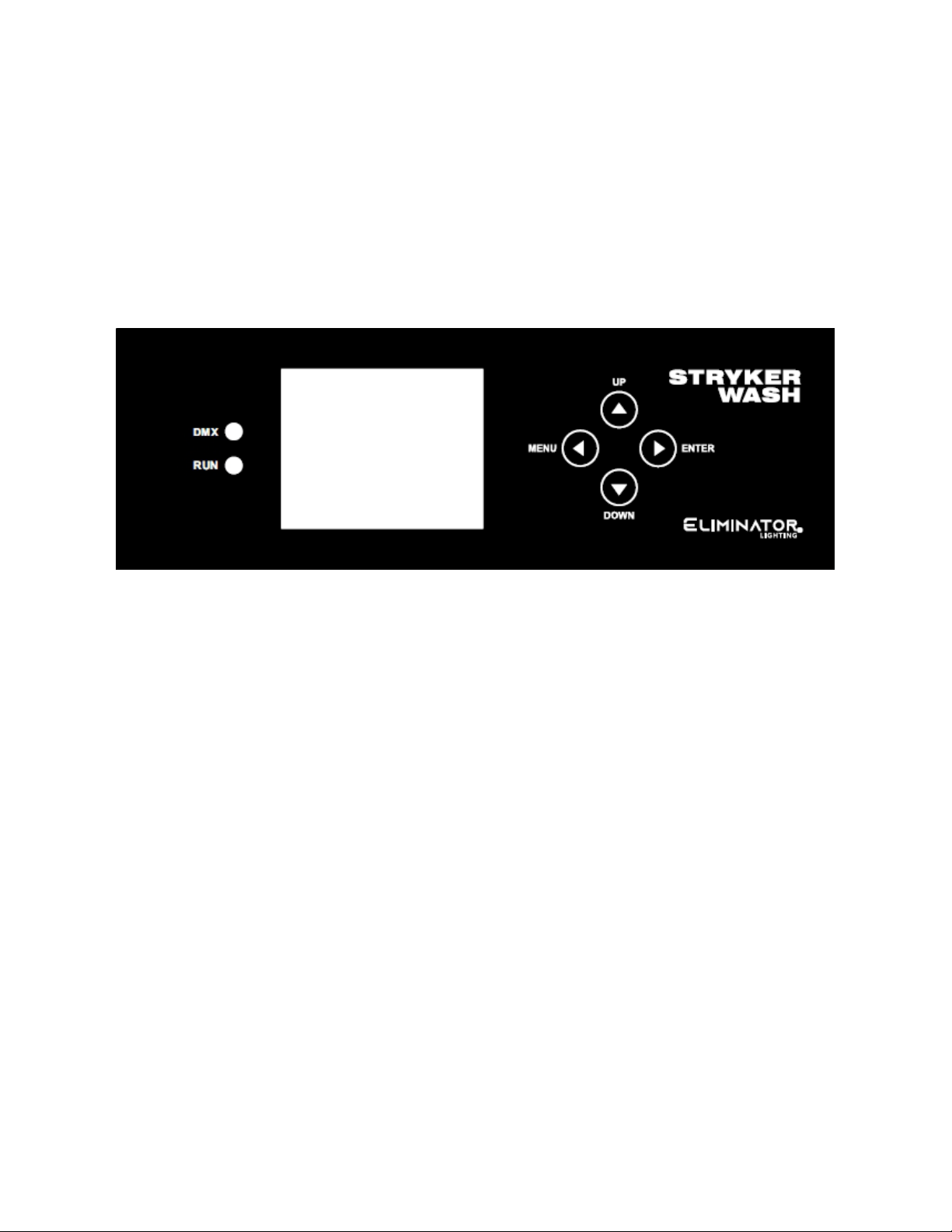
The Stryker Wash features a display screen with a 4-button control pad, which can be used to easily
adjust any device settings.
Pressing the UP and DOWN buttons to scroll through options on the screen. Press ENTER to select
the option currently highlighted on the screen, and enter into the Sub-Menu to adjust that setting, if
applicable. Press MENU to exit without making changes.
The panel also includes an LED which illuminates to indicate that the xture is in DMX mode.
13
Page 14
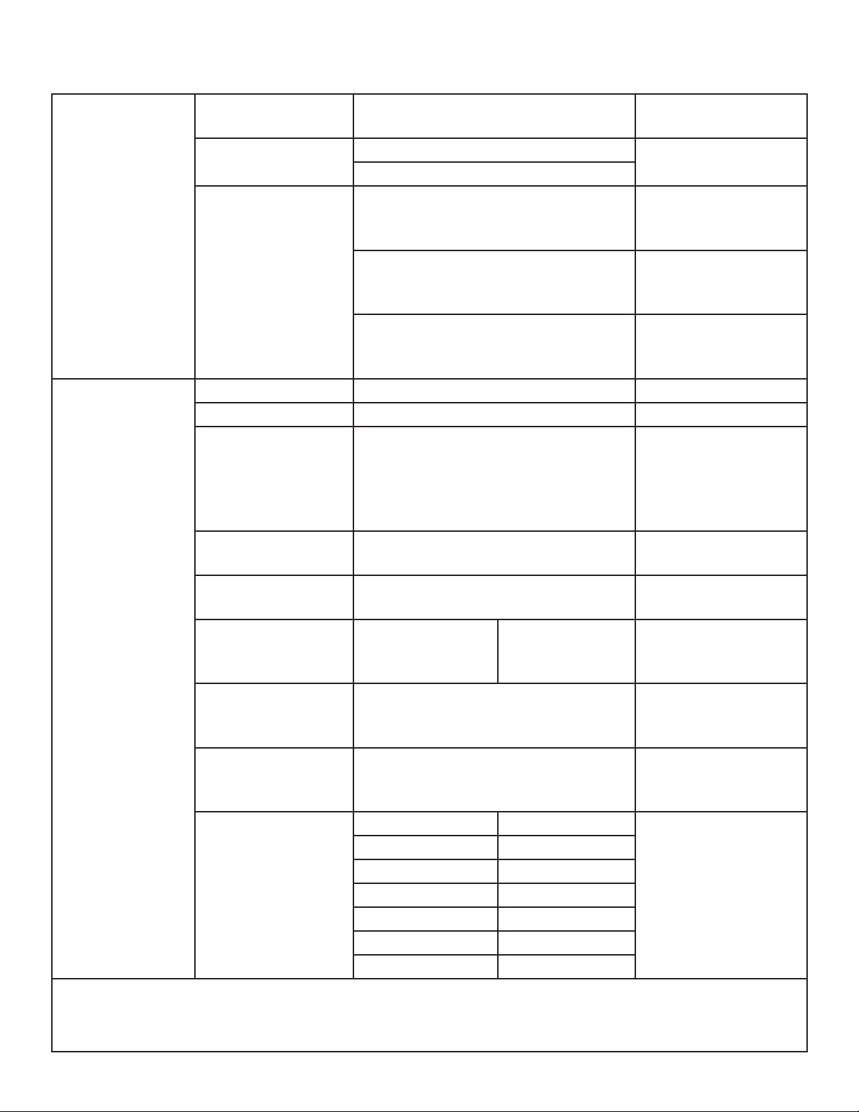
SYSTEM MENU
DMX
SETTINGS
PERSONALITY
Address 001 - 512
Mode
No DMX
Pan Invert Yes / No Invert pan motion
Tilt Invert Yes / No Invert tilt motion
P/T Correction On / Off
Display Reverse Yes / No
Display Intensity 001 - 010
Sound Sensitivity 000 - 100 Default = 080
Reset Yes / No
Factory Restore Yes / No
Home Position
Password = 018
13 Ch
23 Ch
Hold
Auto
Sound
Pan 000 - 255
Tilt 000 - 255
Red 000 - 255
Green 000 - 255
Blue 000 - 255
White 000 - 255
Zoom 000 - 255
Set DMX starting address
Select DMX channel
mode
Fixture holds last
setup if DMX signal
is lost
Fixture defaults to
selected Auto mode
if DMX signal is lost
Fixture defaults to
sound mode if DMX
signal is lost
Returns pan/tilt to
intended position
if head is manually
knocked out of position
Flip display orientation
Adjust display brightness
Adjust sensitivity
to sound in sound
mode
Cycles xture power
off then on, and retains current settings
Restore xture to
factory default settings
Set default (“home”)
value for each parameter
CONTINUED ON NEXT PAGE
14
Page 15
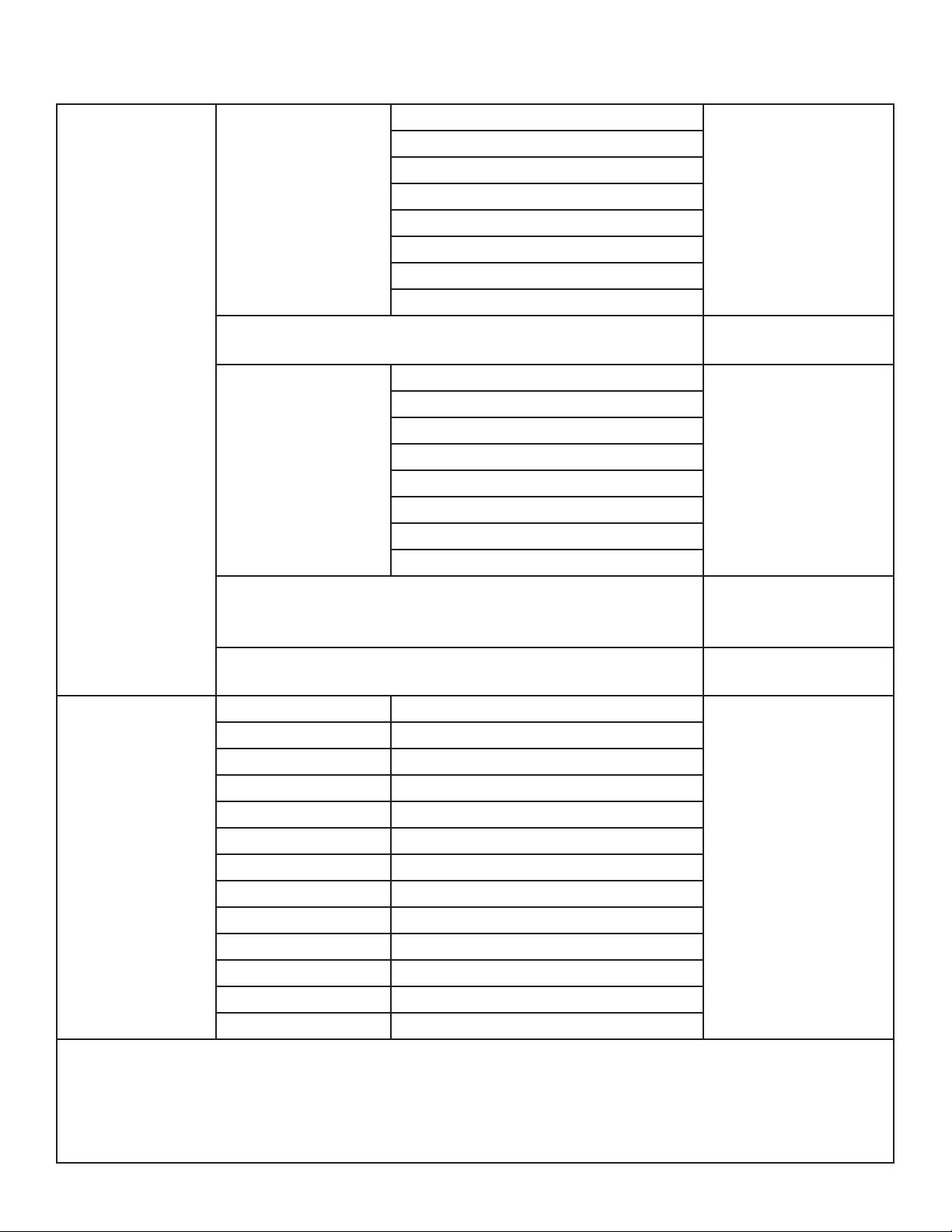
SYSTEM MENU
Auto
Sound
RUN MODE
Primary Auto
Primary Sound
Secondary
Pan 000 - 255
Tilt 000 - 255
Zoom 000 - 255
Red 000 - 255
Green 000 - 255
Blue 000 - 255
MANUAL MODE
White 000 - 255
Linear Color Temp 000 - 255
Ring Macros 000 - 255
Strobe 000 - 255
Dimmer 000 - 255
Pan/Tilt Speed 000 - 255
Special 000 - 255
Auto Mode 1
Auto Mode 2
Auto Mode 3
Auto Mode 4
Auto Mode 5
Auto Mode 6
Auto Mode 7
Auto Mode 8
Auto Mode 1
Auto Mode 2
Auto Mode 3
Auto Mode 4
Auto Mode 5
Auto Mode 6
Auto Mode 7
Auto Mode 8
Set xture to run the
selected auto mode
program
Set xture to sound
mode
Set xture as a primary unit that runs
the selected auto
mode program
Set xture as a primary unit that runs in
sound mode
Set xture as a secondary unit
Manually adjust and
set the value of each
parameter
CONTINUED ON NEXT PAGE
15
Page 16
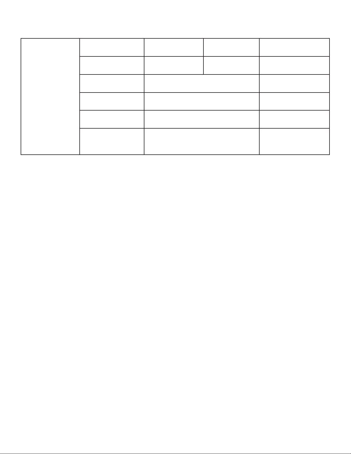
SYSTEM MENU
SYS INFO
On Time xxH xxM
Total Time xxxxxH xxM
Version Vx.xxx
Running Mode DMX xx Ch
Address xxx
Temperature
xxx °F
H = hours,
M = mins
H = hours,
M = mins
Time on since last
power cycle
Total lifetime hours
Current software version
Displays selected
DMX channel mode
Displays current
DMX address
Displays current xture operating temperature
16
Page 17
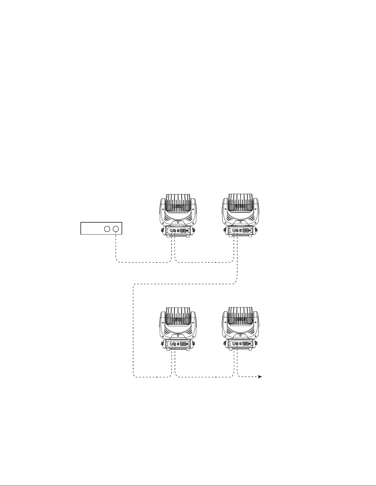
DMX SET UP
DMX-512: DMX is short for Digital Multiplex. This is a universal protocol used as a form of commu-
nication between intelligent fixtures and controllers. A DMX controller sends DMX data instructions
from the controller to the fixture. DMX data is sent as serial data that travels from fixture to fixture via
the DATA “IN” and DATA “OUT” XLR terminals located on all DMX fixtures (most controllers only have
a DATA “OUT” terminal).
DMX Linking: DMX is a language allowing all makes and models of different manufacturers to be
linked together and operate from a single controller, as long as all fixtures and the controller are
DMX compliant. To ensure proper DMX data transmission, try to use the shortest cable path possible
when linking several DMX fixtures. The order in which fixtures are connected in a DMX line does not
influence the DMX addressing. For example, a fixture assigned a DMX address of 1 may be placed
anywhere in a DMX line: at the beginning, at the end, or anywhere in the middle. When a fixture is
assigned a DMX address of 1, the DMX controller knows to send DATA assigned to address 1 to that
unit, no matter where it is located in the DMX chain.
DMX
CONTROLLER
DMX
IN
DMX
IN
FIXTURE
1
DMX
OUT
FIXTURE
3
DMX
OUT
FIXTURE
2
IN
DMX
OUT
FIXTURE
4
OUT
DMX
DMXINDMX
ADDITIONAL
FIXTURES
Data Cable (DMX Cable) Requirements (For DMX Operation): This unit can be controlled via
DMX-512 protocol. The DMX address is set on the rear panel of the unit. Your unit and your DMX
controller require a standard 3-pin XLR connectors for data input and data output. We recommend
Accu-Cable DMX cables. If you are making your own cables, be sure to use standard 110-120 Ohm
shielded cable (This cable may be purchased at almost all pro lighting stores). Your cables should be
made with a male XLR connector at one end and a female XLR connector at the other. Also remember that DMX cable must be daisy chained and cannot be split.
17
Page 18
DMX SET UP
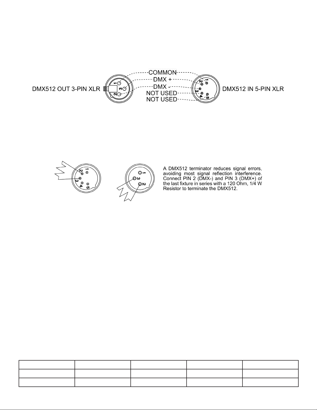
Notice: Be sure to follow the illustration below when making your own cables. Do not use the ground
lug on the XLR connector. Do not connect the cable’s shield conductor to the ground lug or allow the
shield conductor to come in contact with the XLR’s outer casing. Grounding the shield could cause a
short circuit and erratic behavior.
Special Note: Line Termination. When longer runs of cable are used, you may need to use a terminator on the last unit to avoid erratic behavior. A terminator is a 110-120 ohm 1/4 watt resistor which is
connected between pins 2 and 3 of a male XLR connector (DATA + and DATA -). This unit is inserted
in the female XLR connector of the last unit in your daisy chain to terminate the line. Using a cable
terminator (ADJ part number Z-DMX/T) will reduce the risk of erratic behavior.
DMX ADDRESSING.
All fixtures should be given a DMX starting address when using a DMX controller, so the correct fixture responds to the correct control signal. This digital starting address is the channel number from
which the fixture starts to “listen” to the digital control signal sent out from the DMX controller. The
assignment of this starting DMX address is achieved by setting the correct DMX address on the digi-
tal control display on the fixture.
You can set the same starting address for all fixtures or a group of fixtures, or set different addresses
for each individual fixture. Setting all fixtures to the same DMX address will cause all fixtures to react
in the same way. In other words, changing the settings of one channel will affect all the fixtures simul-
taneously.
If you set each fixture to a different DMX address, each unit will start to “listen” to the channel number
you have set, based on the quantity of DMX channels of each fixture. That means changing the settings of one channel will only affect the selected fixture.
For example, when operating this unit in 13-channel mode, you should set the starting DMX address
of the first unit to 1, the second unit to 14 (1 + 13), the third unit to 27 (1 + 13 + 13), and so on. See
the chart below for more details.
CHANNEL MODE UNIT 1 ADDRESS UNIT 2 ADDRESS UNIT 3 ADDRESS UNIT 4 ADDRESS
13 Ch 1 14 27 40
23 Ch 1 24 47 70
18
Page 19

DMX TRAITS
CHANNEL
13Ch 23Ch
1 1 000 - 255 Pan, 0 to 540
2 000 - 255 Pan Fine
2 3 000 - 255 Tilt, 0 to 210
4 000 - 255 Tilt Fine
3 000 - 255 All Red, 0% to 100%
4 000 - 255 All Green, 0% to 100%
5 000 - 255 All Blue, 0% to 100%
6 000 - 255 All White, 0% to 100%
5 000 - 255 Red 1, 0% to 100%
6 000 - 255 Green 1, 0% to 100%
7 000 - 255 Blue 1, 0% to 100%
8 000 - 255 White 1, 0% to 100%
9 000 - 255 Red 2, 0% to 100%
10 000 - 255 Green 2, 0% to 100%
11 000 - 255 Blue 2, 0% to 100%
12 000 - 255 White 2, 0% to 100%
13 000 - 255 Red 3, 0% to 100%
14 000 - 255 Green 3, 0% to 100%
15 000 - 255 Blue 3, 0% to 100%
16 000 - 255 White 3, 0% to 100%
7 17
8 18
DMX
VALUES
000 - 009 No function
010 - 255 Linear 3200K to 10000K
000 - 007 No function
008 - 012 Static 1
013 - 017 Static 2
018 - 022 Static 3
023 - 027 Static 4
028 - 032 Static 5
033 - 037 Static 6
038 - 042 Static 7
043 - 047 Static 8
048 - 052 Static 9
053 - 057 Static 10
FUNCTION
Linear CT
Ring Macros
058 - 062 Static 11
063 - 067 Static 12
CONTINUED ON NEXT PAGE
19
Page 20

DMX TRAITS
CHANNELS
13Ch 23Ch
8 18
9 19
10 20 000 - 255 Dimmer, 0% to 100%
11 21 000 - 255 Zoom, minimum to maximum
12 22 000 - 255 Pan/Tilt Speed, fast to slow
13 23
DMX
VALUES
068 - 072 Static 13
073 - 077 Static 14
078 - 082 Static 15
083 - 087 Static 16
088 - 092 Static 17
093 - 097 Static 18
098 - 102 Static 19
103 - 107 Static 20
108 - 112 Static 21
113 - 117 Static 22
118 - 122 Static 23
123 - 181 Color Jump, slow to fast
182 - 240 Color Fade, slow to fast
241 - 255 Sound Auto Play
000 - 009 Shutter Closed
010 - 250 Strobe Effect, slow to fast
251 - 255 Shutter Open
000 - 010 No Function
011 - 020 XY Auto Run 1
021 - 030 XY Auto Run 2
031 - 040 XY Auto Run 3
041 - 050 XY Auto Run 4
051 - 060 XY Auto Run 5
061 - 070 XY Auto Run 6
071 - 080 XY Auto Run 7
081 - 090 XY Auto Run 8
091 - 230 Sound XY Auto Run
231 - 240 Reset after 3 seconds
241 - 255 No function
FUNCTION
Ring Macros (continued)
Shutter
Special Functions
20
Page 21

PRIMARY-SECONDARY SET UP
This function allows you to link units together to run in a Primary-Secondary set-up, in which one unit
will act as the controlling unit and the others will react to the controlling unit’s built-in programs. Any
unit can be configured to act as a Primary or as a Secondary, but only one unit in a given system can
be programmed to act as the Primary.
Primary-Secondary Connections and Settings:
1. Daisy chain your units via the XLR connectors on the rear panels of each unit. Use standard XLR
data cables to link your units together. Remember that the male XLR connector is the input and
the female XLR connector is the ouput. The first unit in the chain (primary) will use the female XLR
connector only. The last unit in the chain will use the male XLR connector only.
2. Use the display screen and control panel to navigate to the Run Mode, and press ENTER.
3. Among other options, the fixture can be set to Primary Auto, Primary Sound, or Secondary. Set the
unit you would like to act as a primary to either “Primary Auto” (to run an internal program on the
primary unit) or “Primary Sound” (to run the primary fixture in sound active mode).
4. If you selected “Primary Auto”, you will also need to use the UP and DOWN buttons to select one
of 8 available programs to run, then press ENTER to confirm.
5. Set each Secondary unit to the “Secondary” setting in the Run Mode menu, then press ENTER.
Make sure that only one unit is designated as the Primary, while all other units are designated as
Secondaries.
6. The secondary units will act in conjunction with the primary unit.
POWER LINKING
This feature allows multiple units to be linked together by way of the power input and output sock-
ets. To do so, make sure the fixtures are all switched off, then connect the “Power In” socket of the
first unit to the power source. Next, connect the “Power Out” socket of the first unit to the “Power In”
socket of the second unit. Continue in this manner until the “Power Out” socket of each fixture is connected to the “Power In” socket of the next fixture in line (except for the “Power Out” socket of the
last unit, which will remain unused). Once the units have been switched on, they should all be able to
receive power via these connections.
The maximum number of devices that can be connected in this manner is as follows:
• 2 units @120v
• 3 units @230v
After this quantity has been reached, a new power outlet must be used to accommodate additional
devices.
Linked devices must be of the same make and model type. DO NOT mix devices!
21
Page 22

MAINTENANCE GUIDELINES
DISCONNECT POWER BEFORE PERFORMING ANY MAINTENANCE!
CLEANING
Frequent cleaning is recommended to ensure proper function, optimized light output, and an extended life. The frequency of cleaning depends on the environment in which the fixture operates: damp,
smoky, or particularly dirty environments can cause greater accumulation of dirt on the fixture’s optics.
Clean the external lens surface regularly with a soft cloth to avoid dirt/debris accumulation.
NEVER use alcohol, solvents, or ammonia-based cleaners.
MAINTENANCE
Regular inspections are recommended to ensure proper function and extended life. There are
no user serviceable parts inside this fixture. Please refer all other service issues to an authorized
Eliminator service technician. Should you need any spare parts, please order genuine parts from your
local Eliminator dealer.
Please refer to the following points during routine inspections:
A. A detailed electrical check by an approved electrical engineer every three months, to make sure
the circuit contacts are in good condition and prevent overheating.
B. Be sure all screws and fasteners are securely tightened at all times. Loose screws may fall out
during normal operation, resulting in damage or injury as larger parts could fall.
C. Check for any deformations on the housing, color lenses, rigging hardware, and rigging points
(ceiling, suspension, trussing). Deformations in the housing could allow for dust to enter into the
fixture. Damaged rigging points or unsecured rigging could cause the fixture to fall and seriously
injure a person(s).
D. Electric power supply cables must not show any damage, material fatigue, or sediments.
NEVER remove the ground prong from the power cable.
SOFTWARE UPDATES
Please contact Eliminator service for assistance with updating your device’s software.
22
Page 23
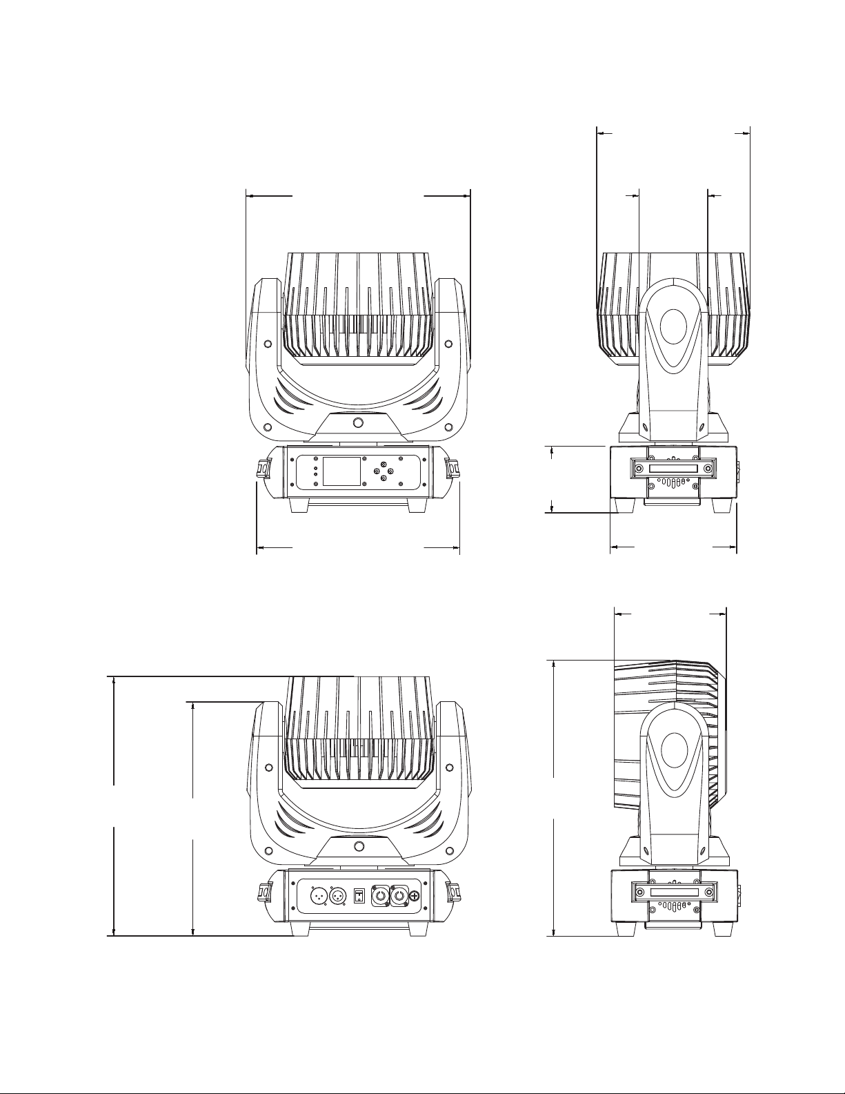
DIMENSIONAL DRAWINGS
8.7in. [222mm]
12.8in. [324mm]
11.6in. [294mm]
3.9in.
[99mm]
3.8in.
[96mm]
7.2in.
[183mm]
14.7in.
[375mm]
13.3in.
[338mm]
6.4in.
[162mm]
15.7in.
[399mm]
Drawings not shown to scale.
23
Page 24

SPECIFICATIONS
Light Source:
• 19x 12W RGBW (4-IN-1) LEDs
• 50,000 Hours Life
Features:
• Fast, precise, pan & tilt movements
• Three zone DMX control mode
• Primary / Secondary stand alone mode
• Motorized Zoom: 6 ~ 50°
• Linear CT DMX control channel: 3200K-10000K
• Up to 18 Strobe flashes per second
Connections:
• DMX Data In/Out: 3-pin XLR
• Power In: Blue Locking indoor power connection
• Power Out: White Locking indoor power connection
Control:
• Color LCD display with touch buttons
• 2 DMX channel modes: 13 & 23 channels
• Protocols: DMX-512, Auto and Sound control modes
• With Wired Digital Communication Network
Pan/Tilt:
• Pan/Tilt: 540-degrees / 210-degrees
• 16-bit Fine Pan
• 16-bit Fine Tilt
Electrical:
• Multi-voltage operation: 100-240V, 50/60Hz
• Maximum power draw: 300W
Dimensions & Weight:
• Dimensions (LxWxH): 8.7” x 12.8” x 15.7” / 222mm x 324mm x 399mm
• Weight: 18.1 lbs. / 8.2 kg.
Technical:
• Operating environment: Indoor 5°~104°F (-15º-40ºC)
• Fan Cooled
• Housing: Black Composite Plastic
Approval / IP Rating:
• CE | IP20
Please Note: Specifications and improvements in the design of this unit and this manual are subject to change without any
prior written notice.
24
Page 25

FCC INFORMATION
FCC STATEMENT
This device complies with Part 15 of the FCC Rules. Operation is subject to the following two conditions:
(1) this device may not cause harmful interference, and (2) this device must accept any interference
received, including interference that may cause undesired operation.
FCC RADIO FREQUENCY INTERFERENCE WARNINGS & INSTRUCTIONS
Please note that changes or modications of this product is not expressly approved by the party
responsible for compliance could void the user’s authority to operate the equipment. This product
has been tested and found to comply with the limits as per Part 15 of the FCC Rules. These limits are
designed to provide reasonable protection against harmful interference in a residential installation. This
device uses and can radiate radio frequency energy and, if not installed and used in accordance with
the included instructions, may cause harmful interference to radio communications. However, there is
no guarantee that interference will not occur in a particular installation. If this device does cause harmful
interference to radio or television reception, which can be deter- mined by turning the device off and
on, the user is encouraged to try to correct the interference by one or more of the following methods:
• Reorient or relocate the device.
• Increase the separation between the device and the receiver.
• Connect the device to an electrical outlet on a circuit different from which the radio receiver is
connected.
• Consult the dealer or an experienced radio/TV technician for help.
Energy Saving Matters (EuP 2009/125/EC)
Saving electric energy is a key to help protecting the environment. Please turn off all electrical products
when they are not in use. To avoid power consumption in idle mode, disconnect all electrical equipment
from power when not in use. Thank you!
25
Page 26

This page intentionally left blank.
26
Page 27

 Loading...