

Page 1

STEALTH BEAM
Introduction:
The Stealth Beam is a DMX intelligent moving head unit. The Stealth Beam has 3 operating modes;
sound active mode, show mode, or controlled via DMX controller. The Stealth Beam has 2 DMX
Channel modes; 5 or 17 channels. The unit can be run as a stand alone unit or in a Master/Slave set
up. This unit has been tested and there is no assembly required. Follow the instructions on the
following pages to operate your fixture. To enhance the beams effects you can use a fog machine.
CAUTION! Please read and understand these instructions before installing or operating this unit.
CAUTION! Please read and
understand these instructions
before installing or operating
this unit.
Fuse Replacement: Locate and remove
the unit’s power cord. Once the cord
has been removed, the fuse holder is
located inside the power socket. Insert
a flat-head screw driver into the fuse
holder and gently pry out the holder.
Remove the bad fuse and replace with
a new one. The fuse holder has a built-in
second holder for a spare fuse.
©Eliminator® Los Angeles, CA. - www.EliminatorLighting.com
SPECIFICATIONS:
Model: Stealth Beam
Supply Voltage: 100V-240V 50/60Hz
LED: 1 x 60W RGBW 4-in-1 LED
Weight: 8.5lbs./ 3.8 kgs.
Size: 5.75” (L) x 9.4” (W) x 11.22” (H)
Fuse: 2 Amp
Power Consumption: 75W
Working Position: Any Safe position
Duty Cycle: None
DMX Channels: 2 DMX Channel Modes:
5 Channel Mode &
17 Channel Mode
Colors: RGBW
Warranty: 1 Year
Page 2

Addr: In this menu you can set the DMX address. Press the Up or Down buttons until “AXXX” is displayed.
“XXX” is the current displayed DMX address. Press Enter and use the UP or Down buttons to nd your desired address. When you have found your desired address press the Enter button to set it. NOTE: To display
the DMX address you must rst select any show, then press the MENU button to exit and then follow
the directions above.
Chnd: The Stealth Beam has 2 DMX channel modes; 5 channel mode and 17 channel mode. In this menu you
can select your desired channel mode. Press the Up or Down buttons until “CHnd” is displayed and press
ENTER. Either “16CH” or “5CH” will be displayed. Use the Up and Down buttons to toggle between the two
modes and press Enter to make your selection and press Menu to exit.
SPnd (Sound Active Speed): In this menu you can adjust the sound active moving speed. Press the Up or
Down buttons until “SPnd” is displayed and press ENTER. Either “LoSP” (Low Speed) or “HISP” (High Speed)
will be displayed. Use the Up and Down buttons to toggle between the two speed and press Enter to make
your selection. Press the Menu button to exit.
SOUN (Sound Active): In this menu you can activate Sound Active mode. Press the Up or Down buttons until
“SOUN” is displayed and press Enter. Either “On” or “O” will be displayed. Use the Up and Down buttons
toggle between the choices and press Enter to make your selection. Press the Menu button to exit.
SHnd (Show Mode): In this menu you can activate the 1 of 8 show mode’s. Press the Up or Down buttons
until “SHnd” is displayed and press Enter. Either 1 of 8 shows will be displayed. Use the Up and Down
buttons nd your desired show and press Enter to make your selection. Press the Menu button to exit
SLnd (Master/Slave): In this menu you can designate the xture as either a Master or Slave in a master-slave
set up. Press the Up or Down buttons until “SLnd” is displayed and press Enter. Either “Mast” or “SL 1 will be
displayed. Use the Up and Down buttons to nd your desired setting and press Enter to make your selection.
Press the Menu button to exit
PAn (Reverse Pan): In this menu you can reverse the Pan function. Press the Up or Down buttons until “PAn”
is displayed and press Enter. Press the Up or Downs buttons until “On” is
displayed, and press Enter. Press the Menu button to exit. This function works better when you have two units
connected in a Master/Slave setup. Have one unit set to reverse Pan and the other unit in normal Pan.
tIL ( Reverse Tilt): In this menu you can reverse the Tilt function. Press the Up or Down buttons until “tIL” is
displayed and press Enter. Press the Up or Downs buttons until “On” is
displayed, and press Enter. Press the Menu button to exit. This function works better when you have two units
connected in a Master/Slave setup. Have one unit set to reverse Tilt and the other unit in normal Tilt.
dISP (Display): In this menu you can “ip” the display 180°. Press the Up or Down buttons until “dISP” is
displayed and press Enter. Either “ON” or “OFF” will now be displayed. If you want to “ip” the display press
the Up button so that “ON” is displayed, and press Enter. Press the Menu button to exit.
rSt (Reset): In this menu you can activate reset function. Press the Press the Up of Down buttons until “rSt”
is displayed and press Enter. The unit will now begin to reset. Press the Menu button to exit.
rFAC (Default Setting): In this menu you can reset the unit to it default settings. Press the Up or Down buttons until “rFAC” is displayed and press Enter. Select “On” and press Enter. Press the Menu button to exit.
©Eliminator® Los Angeles, CA. - www.EliminatorLighting.com
Page 3

OPERATION:
UNIVERSAL DMX CONTROL: This unit allows you to use any universal DMX-512 controller to control head
movement, the color wheel, the gobo wheel, and the shutter (strobe). A DMX controller allows you to create
unique programs tailored to your individual needs. Follow the set-up specifications that are included with your
DMX controller.
1. The Stealth Beam has two DMX channel modes; 5 DMX channels and 17 DMX channels.
2. Press the Up or Down buttons until “Chnd” is displayed, and press Enter.
3. Press the Up or Down buttons until your desired DMX channel mode is displayed, and press Enter.
4. Press the Mode button until “AXXX” is displayed. “XXX” is the current displayed DMX addess.
Press the Enter button.
4. Use the Up and Down buttons to find your desired address and press Enter.
5. Connect your DMX Controller and use the controller’s faders to control the various DMX fixture traits.
6. For longer cable runs (more than a 100 feet) use a terminator on the last fixture.
7. For help operating in DMX mode consult the manual included with your DMX controller.
SOUND ACTIVE MODE:
1. To activate Sound Active mode, press the Up or Down buttons until “SOUN” is displayed, and press Enter.
2. Either “On” or “Off” will be displayed. To activate sound active mode press the Up or Down buttons until
“On” is displayed, and press Enter to select. Press the Menu button to exit
3. To adjust the movement speed in sound active mode press the Up or Down buttons until “SPnd” is
displayed. Either “HISP” (High Speed) or “LoSP” (Low Speed) will be displayed. Use the Up or Down
buttons to switch between the two modes and press Enter to make your selection. Press the Menu button
to exit.
SHOW MODE:
1. To activate Show mode, press the Up or Down buttons until “SHnd” is displayed, and press Enter.
2. 1 of 8 shows will be displayed. Use the Up or Down buttons to scroll through the shows and press Enter
to make your selection. Show 0 runs a random show. Press the Menu button to exit.
MASTER-SLAVE SET UP: This function will allow you to link up to 16 units together and operate without a
controller. The units can be sound active or in show mode. In a Master-Slave set up one unit will act as the controlling unit and the others will react to the controlling units programs. Any unit can act as a Master or as a Slave.
1. Using approved DMX data cables, daisy chain your units together via the XLR connector on the rear of the
units. Remember the Male XLR connector is the input and the Female XLR connector is the output. The
rst unit in the chain (master) will use the female XLR connector only - The last unit in the chain will use the
male XLR connector only. For longer cable runs we suggest a terminator at the last fixture.
2. On the Master unit press the Menu button until “SLnd” is displayed, and press Enter. Use the UP and
DOWN buttons to scroll to the “Mast” setting and press Enter. Press the Menu button to exit.
3. After setting the Master unit to the master setting find and set your desired operating mode.
4. On the slave units press the Menu button until “SLnd” is displayed, and press Enter. Press the Up or
Down buttons until “SL 1” and press Enter. Press the Menu button to exit.
5. The slave units will now follow the Master unit.
©Eliminator® Los Angeles, CA. - www.EliminatorLighting.com
Page 4

OFFSET MENU -
To enter the Oset Menu, press the Up or Down buttons until “Ad t” is displayed and press Enter. “P000” will
now be displayed. Press the Up button so that the display reads “P018” and press Enter. In this submenu you
are able to adjust the home positions of the pan and tilt motor’s, gobo and color wheel’s, focus motor, and
prism. If you select delete, it will reset all home positions to “0000”. Press the Menu button to exit.
Ad t:
(P) - Use the Up and Down buttons to adjust the oset of the Pan motor.
(t) - Use the Up and Down buttons to adjust the oset of the Tilt motor.
(R) - Use the Up and Down buttons to adjust the oset of the Red Color.
(g) - Use the Up and Down buttons to adjust the oset of the Green Color.
(b) - Use the Up and Down buttons to adjust the oset of the Blue Color.
(U) - Use the Up and Down buttons to adjust the oset of the White Color.
DMX TRAITS: 5 CHANNELS
CHANNEL 1: PAN
CHANNEL 2: TILT
CHANNEL 3: COLORS
0 - 7 = NOTHING
8 - 17 = RED
18 - 27 = GREEN
28 - 37 = BLUE
38 - 47 = WHITE
48 - 57 = RED/GREEN
58 - 67 = GREEN/BLUE
68 - 77 = BLUE/WHITE
78 - 87 = RED/WHITE
88 - 97 = RED/GREEN/BLUE
98 - 107 = GREEN/BLUE/WHITE
108 - 117 = RED/BLUE/WHITE
118 - 127 = RED/GREEN/WHITE
128 - 137 = RED/GREEN/BLUE/WHITE
138 - 188 = MACRO COLOR CHANGE
189 - 239 = MACRO COLOR LINE
240 - 255 = SOUND ACTIVE CHANGE
CHANNEL 4: COLOR CHANGE/FADE SPEED
(USED WITH CHANNEL 3 VALUES
138 - 239)
0 - 255 = SLOW - FAST
CHANNEL 5: PAN/TILT PROGRAMS
0 - 7 = NOTHING
8 - 32 = PROGRAM 1
33 - 58 = PROGRAM 2
59 - 84 = PROGRAM 3
85 - 110 = PROGRAM 4
111 - 136 = PROGRAM 5
137 - 162 = PROGRAM 6
163 - 188 = PROGRAM 7
189 - 214 = PROGRAM 8
215 - 240 = PROGRAM 9
241 - 255 = SOUND ACTIVE
©Eliminator® Los Angeles, CA. - www.EliminatorLighting.com
Page 5

DMX TRAITS: 16 CHANNELS
CHANNEL 1: PAN
CHANNEL 2: PAN FINE
CHANNEL 3: TILT
CHANNEL 4: TILT FINE
CHANNEL 5:
0 - 255 = RED 1
CHANNEL 6:
0 - 255 = GREEN 1
CHANNEL 7:
0 - 255 = BLUE 1
CHANNEL 8:
0 - 255 = WHITE 1
CHANNEL 9: COLOR EFFECT
00 - 7 = NOTHING
8 - 17 = RED
18 - 27 = GREEN
28 - 37 = BLUE
38 - 47 = WHITE
48 - 57 = RED/GREEN
58 - 67 = GREEN/BLUE
68 - 77 = BLUE/WHITE
78 - 87 = RED/WHITE
88 - 97 = RED/GREEN/BLUE
98 - 107 = GREEN/BLUE/WHITE
108 - 117 = RED/BLUE/WHITE
118 - 127 = RED/GREEN/WHITE
128 - 137 = RED/GREEN/BLUE/WHITE
138 - 188 = COLOR CHANGE
189 - 239 = COLOR FADE
240 - 255 = SOUND ACTIVE CHANGE
CHANNEL 13: PAN MOVEMENT SPEED
0 - 255 = MOVEMENT SPEED FAST - SLOW
CHANNEL 14: TILT MOVEMENT
0 - 7 = NOTHING
8 - 255 = TILT MOVE FORWARD - BACK
SLOW - FAST
CHANNEL 15: COLOR CHANGE/FADE SPEED
(USED WITH CHANNEL 9 VALUES
138 - 239)
0 - 255 = SLOW - FAST
CHANNEL 16: PAN/TILT PROGRAMS
0 - 7 = NOTHING
8 - 32 = PROGRAM 1
33 - 58 = PROGRAM 2
59 - 84 = PROGRAM 3
85 - 110 = PROGRAM 4
111 - 136 = PROGRAM 5
137 - 162 = PROGRAM 6
163 - 188 = PROGRAM 7
189 - 214 = PROGRAM 8
215 - 240 = PROGRAM 9
241 - 255 = SOUND ACTIVE
CHANNEL 17:PAN/TILT PROGRAM SPEED
(GIVE THE SPEED MOVEMENT 10S TO START)
0 - 50 = NOTHING
51 - 100 = SPEED MODE TO HIGH (10S)
101 - 150 = NOTHING
151 - 200 = SPEED MODE TO LOW (10S)
201 - 250 = NOTHING
201 - 255 = RESET (WILL TAKE 10S TO RESET)
CHANNEL 10: MASTER DIMMER
0 - 255 = 0% - 100%
CHANNEL 11: SHUTTER/STROBING
0 - 4 = SHUTTER CLOSED
5 - 250 = STROBING SLOW - FAST
251 - 255 = SHUTTER OPEN
CHANNEL 12: PAN MOVEMENT
0 - 7 = NOTHING
8 - 127 = PAN MOVE CLOCKWISE
SLOW - FAST
128 - 255 = PAN MOVE
COUNTER CLOCKWISE FAST - SLOW
©Eliminator® Los Angeles, CA. - www.EliminatorLighting.com
Page 6
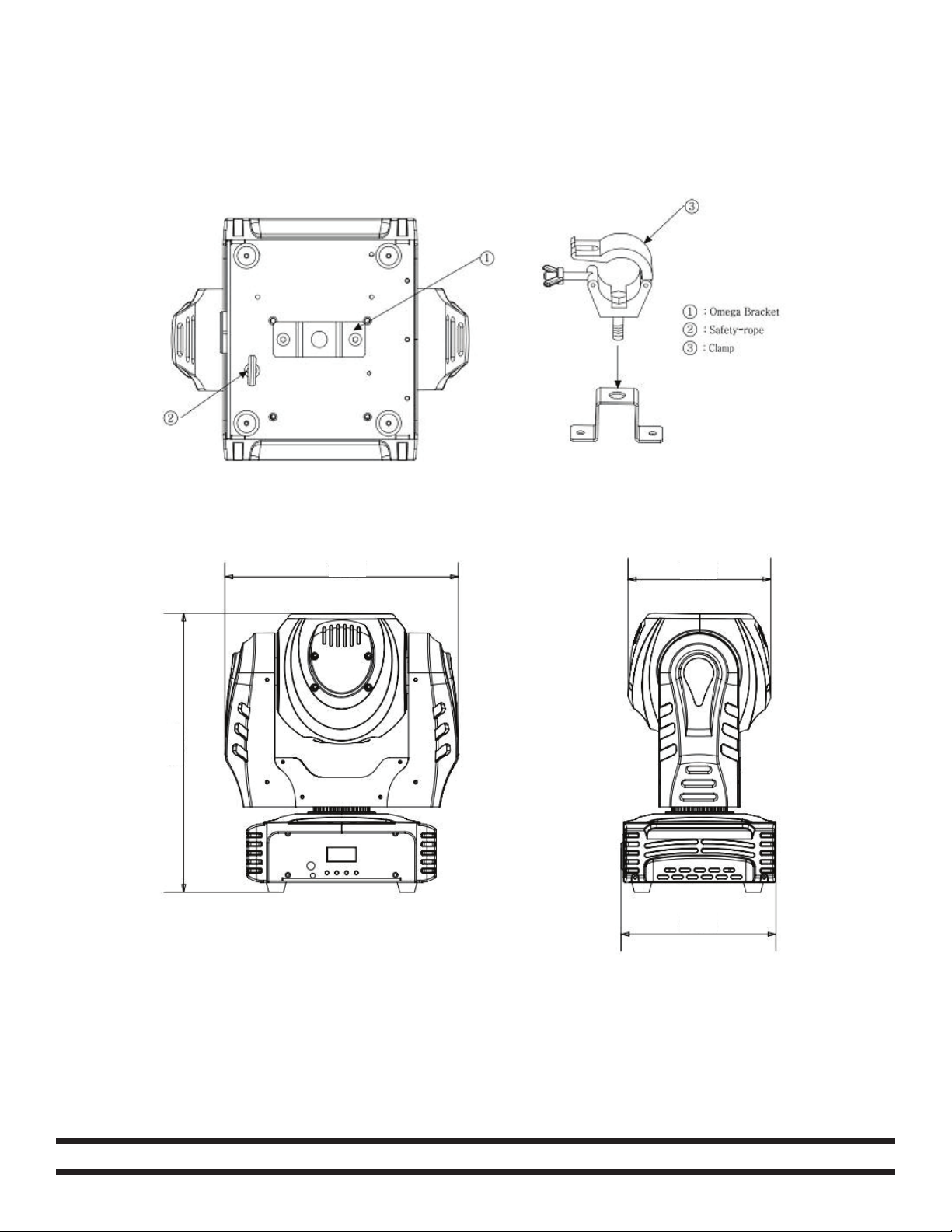
Screw one clamp (3) via a M12 screw and nut to the included bracket (1). Attach the bracket using
the provided screws to the bottom of the Stealth Beam. Attach the included eyehole screw (2) to
the bottom of the xture and and pull the safety-cable through eyehole screw and over the trussing
system or a safe xation spot. Insert the end in the carabine and tighten the safety screw.
Dimesnional Drawings
9.4”/239mm
11.22”/285mm
5.75”/146mm
6.22”/158mm
1 Year Limited Warranty: Eliminator Lighting warranty is valid from the date of purchase. Our
1 year limited warranty covers manufacturing defects only. Serial number, place of purchase with
dated valid receipt must be submitted at time of service. Eliminator Lighting warranty does not cover
items or parts prone to wear and tear: motors, fuses, brushes and belts. Eliminator Lighting warranty
is only valid with-in the United States.
©Eliminator® Los Angeles, CA. - www.EliminatorLighting.com
 Loading...