

Page 1
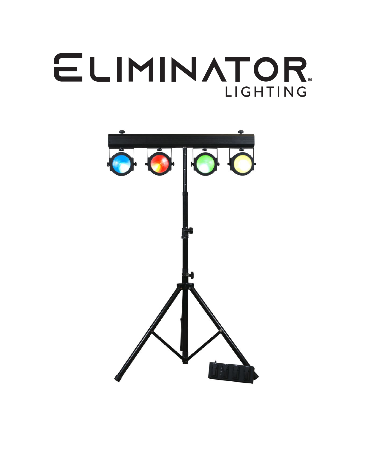
DOTZ TPAR SYSTEM PLUS
User Manual
Page 2
©2023 Eliminator Lighting all rights reserved. Information, specications, diagrams, images, and in-
structions herein are subject to change without notice. Eliminator logo and identifying product names
and numbers herein are trademarks of Eliminator Lighting. Copyright protection claimed includes all
forms and matters of copyrightable materials and information now allowed by statutory or judicial law
or hereinafter granted. Product names used in this document may be trademarks or registered trademarks of their respective companies and are hereby acknowledged. All non-Eliminator brands and
product names are trademarks or registered trademarks of their respective companies.
Eliminator Lighting and all afliated companies hereby disclaim any and all liabilities for property,
equipment, building, and electrical damages, injuries to any persons, and direct or indirect economic
loss associated with the use or reliance of any information contained within this document, and/or as a
result of the improper, unsafe, insufcient and negligent assembly, installation, rigging, and opera-tion
of this product.
Eliminator Lighting
6122 S. Eastern Ave. Los Angeles, CA. 90040
323-582-2650 | Fax 323-532-2941 | www.adj.com | [email protected]
ADJ SUPPLY Europe B.V
Junostraat 2 6468 EW Kerkrade, The Netherlands
+31 (0)45 546 85 00 | Fax +31 45 546 85 99
www.adj.eu | [email protected]
ADJ PRODUCTS GROUP Mexico
AV Santa Ana 30 Parque Industrial Lerma, Lerma, Mexico 52000
+52 (728) 282-7070
DOCUMENT VERSION
Due to additional product features and/or enhancements, an updated version of this
document may be available online.
Please check www.adj.com for the latest revision/update of this manual before
beginning installation and/or programming.
Date
10/12/23 1.0 3 / 5 / 9 / 12 / 18 Ch Initial release
Document
Version
DMX Channel Mode Notes
2
Page 3

CONTENTS
General Information 4
Limited Warranty (USA Only) 5
Warranty Registration | Features 6
Safety Guidelines 7
System Menu 8
Primary-Secondary Conguration | Universal DMX Control 11
Foot Controller 12
Dotz RF Remote 13
DMX Setup 14
DMX Traits 17
Photometric Chart | Power Cord Daisy Chain 19
Dimmer Curves 20
Alternate Lighting Installation 21
Fuse Replacement | Cleaning | Trouble Shooting 22
Specications 23
3
Page 4

GENERAL INFORMATION
GENERAL INSTRUCTIONS
To optimize the performance of this product, please read these operating instructions carefully to
familiarize yourself with the basic operations of the units in this pack. These instructions contain important
safety information regarding the use and maintenance of these units. Please keep this manual with the
units for future reference.
UNPACKING
Every pack has been thoroughly tested and has been shipped in perfect operating condition. Carefully
check the shipping carton for damage that may have occurred during shipping. If the carton appears to
be damaged, carefully inspect your xtures and accessories for any damage and be sure all accessories
necessary to operate the units have arrived intact. In the event that damage is been found or parts are
missing, please contact our toll free customer support number for further instructions. Do not return this
unit to your dealer without rst contacting customer support.
INTRODUCTION
The Dotz TPar System Plus includes high performance, DMX intelligent, moving head LED xtures,
which are well suited for use in retail stores, displays, mood, architectural, interior and exterior decoration,
and clubs. Units can be operated either in stand alone mode, or in a primary/secondary conguration,
and can also be controlled via a DMX controller.
CUSTOMER SUPPORT
Tel: (323) 213-4592 | Fax: (323) 582-2941
www.adj.com | [email protected]
Warning! To prevent or reduce the risk of electrical shock or re, do not expose this unit to rain or moisture.
Caution! There are no user serviceable parts inside this unit. Do not attempt any repairs yourself, as doing
so will void your manufacturer’s warranty. In the event that your unit requires service, please contact Elimi-
nator Lighting for assistance.
PLEASE recycle the shipping carton when ever possible.
4
Page 5

LIMITED WARRANTY (USA ONLY)
A. Eliminator Lighting, an ADJ Products, LLC brand, hereby warrants, to the original purchaser, Eliminator
Lighting products to be free of manufacturing defects in material and workmanship for a prescribed
period from the date of purchase (see specic warranty period on reverse). This warranty shall be
valid only if the product is purchased within the United States of America, including possessions and
territories. It is the owner’s responsibility to establish the date and place of purchase by acceptable
evidence, at the time service is sought.
B. For warranty service, you must obtain a Return Authorization number (RA#) before sending back the
product-please contact ADJ Products, LLC Service Department at 800-322-6337. Send the product
only to the Eliminator Lighting factory. All shipping charges must be pre-paid. If the requested repairs
or service (including parts replacement) are within the terms of this warranty, Eliminator Lighting
will pay return shipping charges only to a designated point within the United States. If the entire
instrument is sent, it must be shipped in its original package. No accessories should be shipped
with the product. If any accessories are shipped with the product, Eliminator Lighting shall have no
liability whatsoever for loss of or damage to any such accessories, or for the safe return thereof.
C. This warranty is void of the serial number has been altered or removed; if the product is modied
in any manner which Eliminator Lighting concludes, after inspection, affects the reliability of the
product, if the product has been repaired or service by anyone other than ADJ Products, LLC factory
unless prior written authorization was issued to purchaser by Eliminator Lighting; if the product is
damaged because not properly maintained as set forth in the instruction manual.
D. This is not a service contact, and this warranty does not include maintenance, cleaning or periodic
check up. During the period specied above, Eliminator Lighting will replace defective parts at
its expense with new or refurbished parts, and will absorb all expenses for warrant service and
repair labor by reason of defects in material or workmanship. The sole responsibility of Eliminator
Lighting under this warranty shall be limited to the repair of the product, or replacement thereof,
including parts, at the sole discretion of Eliminator Lighting. All products covered by this warranty
were manufactured after August 15, 2012, and bear identifying marks to that effect.
E. Eliminator Lighting reserves the right to make changes in design and/or improvements upon its
products without any obligation to include these changes in any products theretofore manufactured.
F. No warranty, whether expressed or implied, is given or made with respect to any accessory supplied
with products described above. Except to the extent prohibited by applicable law, all implied warranties
made by Eliminator Lighting in connection with this product, including warranties of merchantability
or tness, are limited in duration to the warranty period set forth above. And no warranties, whether
expressed or implied, including warranties of merchantability or tness, shall apply to this product
after said period has expired. The consumer’s and/or Dealer’s sole remedy shall be such repair or
replacement as is expressly provided above; and under no circumstances shall Eliminator Lighting
be liable for any loss or damage, direct or consequential, arising out of the use of, or inability to use,
this product.
G. This warranty is the only written warranty applicable to Eliminator Lighting products and supersedes
all prior warranties and written descriptions of warranty terms and conditions heretofore published.
LIMITED WARRANTY PERIODS
• All Eliminator Lighting products (except laser diodes) = 1-year (365 days) Limited Warranty
(Such as: Special Effect Lighting, Intelligent Lighting, UV lighting, Strobes, Fog Machines, Bubble
Machines, Mirror Balls, Par Cans, Trussing, Lighting Stands etc. excluding LED and lamps)
• Laser Products = 1 Year (365 Days) Limited Warranty (excludes laser diodes which have 6
month limited warranty)
• Batteries = 180 Day Limited Warranty (excluding batteries which have a 180 day limited warranty)
5
Page 6

WARRANTY REGISTRATION
This product carries a 2 year (730 days) limited warranty. Please fill out the enclosed warranty card
to validate your purchase and warranty. You may also register this product online at www.adj.com.
All returned service items, whether under warranty or not, must be freight pre-paid and accompanied
by a return authorization (R.A.) number. The R.A. number must be clearly written on the outside of
the return package. A brief description of the problem as well as the R.A. number must also be written
down on a piece of paper included in the shipping carton. If the unit is under warranty, you must provide a copy of your proof of purchase invoice. You may obtain an R.A. number by contacting our cus-
tomer support team on our customer support number. All packages returned to the service department
not displaying an R.A. number on the outside of the package will be returned to the shipper.
FEATURES
• 4 x COB LED Par Wash Fixtures
• 1 x Foot Controller
• 1 x Lighting Stand
• 1 x RF Remote Control
• 1 x Stand Bag
• 1 x Soft Case for Lighting System
• RGB Color Mixing
• Strobing
• Electronic Dimming 0-100%
• Built in Microphone
• DMX-512 protocol
• Five DMX Modes: 3-Channel, 5 Channel, 9 Channel, 12 Channel, & 18 Channel Mode
• 4 Operating Modes - Sound Active, Auto Run, Built-In Programs, or DMX Control
• Power Cord Daisy Chain (see Power Cord Daisy Chain section of this manual)
6
Page 7

SAFETY GUIDELINES
• To reduce the risk of electrical shock or fire, do not expose this unit to rain or moisture
• Do not spill water or other liquids into or on to your unit.
• Always ensure that the voltage of the local power source matches the required voltage of the
device.
• Do not attempt to operate this unit if the power cord has been frayed or broken.
• Do not attempt to remove or break off the ground prong from the electrical cord. This prong is
used to reduce the risk of electrical shock and fire in case of an internal short.
• Disconnect from main power before making any type of connection.
• Do not remove the cover for any reason. There are no user serviceable parts inside.
• Never operate this unit with the cover removed.
• Never plug this unit in to a dimmer pack.
• Always be sure to mount this unit in an area that will allow proper ventilation. Allow about 6”
(15cm) between this device and a wall.
• Do not attempt to operate this unit if it has been damaged in any way.
• This unit is intended for indoor use only, and use of this product outdoors voids all warranties.
• During long periods of non-use, disconnect the unit from main power.
• Always mount this unit in safe and stable matter.
• Power-supply cords should be routed so that they are not likely to be walked on or pinched by
items placed upon or against them, paying particular attention to the point at which they exit from
the unit.
• Cleaning - The fixture should be cleaned only as recommended by the manufacturer. See the
Cleaning section of this manual for details.
• Heat - The appliance should be situated away from heat sources such as radiators, heat registers,
stoves, or other appliances (including ampifiers) that produce heat.
• The fixture should be serviced by qualified service personnel when:
A. The power-supply cord or the plug has been damaged.
B. Objects have fallen onto, or liquid has been spilled into, the appliance.
C. The appliance has been exposed to rain or water.
D. The appliance does not appear to operate normally or exhibits a marked change in
performance.
7
Page 8
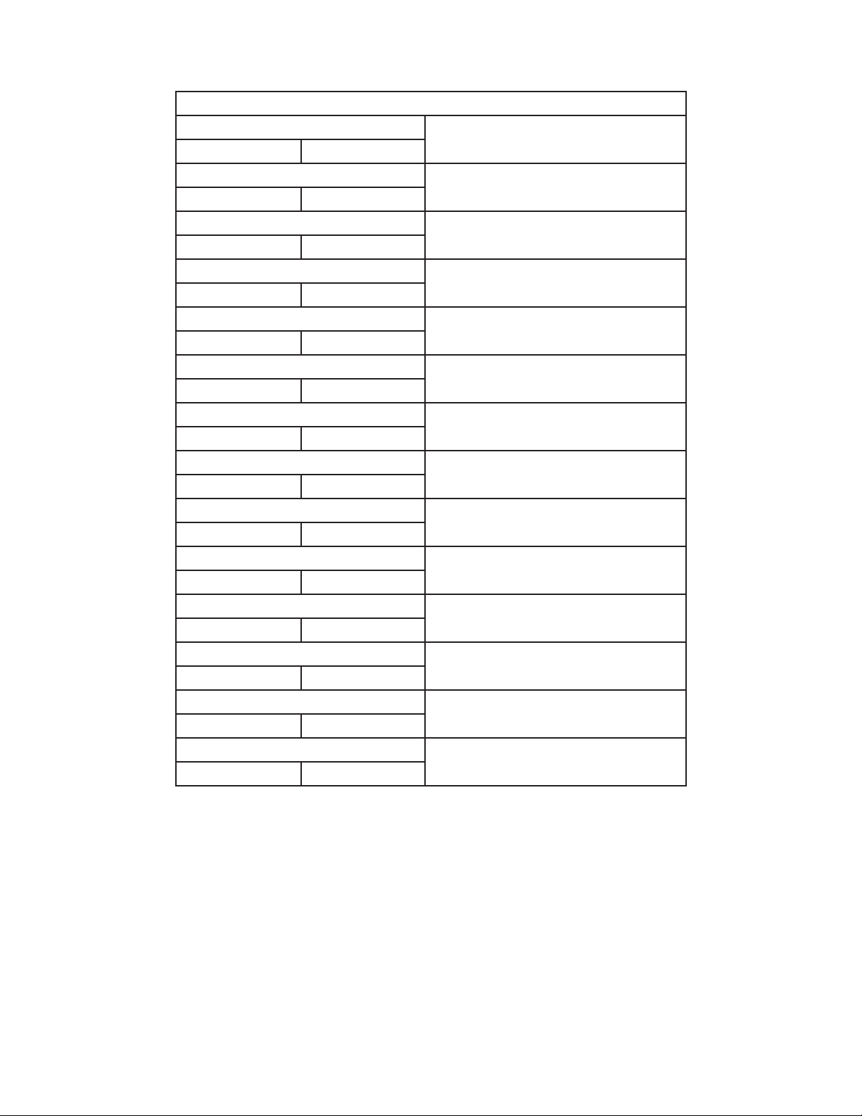
SYSTEM MENU
STATIC COLOR
CL : RGB Flash 00 - 99
Speed 00 - 99 Flash 00 - 99
METEOR
Speed 00 - 99 Flash 00 - 99
Speed 00 - 99 Flash 00 - 99
CHANGE
Speed 00 - 99 Flash 00 - 99
Speed 00 - 99 Flash 00 - 99
Speed 00 - 99 Flash 00 - 99
Speed 00 - 99 Flash 00 - 99
Speed 00 - 99 Flash 00 - 99
Speed 00 - 99 Flash 00 - 99
Speed 00 - 99 Flash 00 - 99
Speed 00 - 99 Flash 00 - 99
Speed 00 - 99 Flash 00 - 99
Speed 00 - 99 Flash 00 - 99
DREAM
FADE
FLOW 1
FLOW 2
FLOW 3
FLOW 4
FLOW 5
FLOW 6
FLOW 7
FLOW 8
FLOW 9
BUILT-IN PROGRAMS
Static color
Flash adjustable
Seven color dreaming
Speed and ash adjustable
Seven color ow
Speed and ash adjustable
Seven color fade
Speed and ash adjustable
Seven color change
Speed and ash adjustable
Seven color chase 1
Speed and ash adjustable
Seven color chase 2
Speed and ash adjustable
Seven color chase 3
Speed and ash adjustable
Seven color chase 4
Speed and ash adjustable
Seven color chase 5
Speed and ash adjustable
Seven color chase 6
Speed and ash adjustable
Seven color chase 7
Speed and ash adjustable
Seven color chase 8
Speed and ash adjustable
Seven color chase 9
Speed and ash adjustable
8
Page 9

SYSTEM MENU
The LCD backlight will shut off after 30 seconds. To re-active the backlight, press and hold the
MODE button for 5 seconds.
DMX Mode - Set the DMX Address and DMX Channel Mode.
1. Press the MENU button until “DMX Mode” is shown on the screen, with “ADDR: XXX” and
“CH:XX” displayed underneath, and press ENTER.
2. “XXX” will now begin to ash. Use the UP and DOWN buttons to nd your desired DMX address,
then press ENTER.
3. “XX” will now begin to ash. Use the UP and DOWN buttons to nd your desired DMX Channel
mode, then press ENTER.
Secondary Mode - Set the unit as a secondary unit in a primary/secondary conguration.
1. Press the MENU button until “Secondry Mode” is displayed.
2. This unit will now follow the designated primary unit.
Sound Mode - The unit will run in sound active mode.
1. Press the MENU button until “Sound Mode” is displayed.
2. Press ENTER to adjust the sound sensitivity.Press ENTER, and the number next to “Sens” will
begin to ash. Use the UP and DOWN buttons to adjust the sound sensitivity. Once the desired
sensitivity level is displayed on the screen, press ENTER to conrm.
3. Press ENTER, and the number next to “FQN” will begin to ash. Use the UP and DOWN buttons
to adjust the amount of times you would like the program to cycle before changing to the next program. Press ENTER to conrm.
Auto Run -
1. Press the MENU button until “Auto Run” is displayed, with “FQN:XX” displayed underneath. “XX”
represents the number of times a program will run before cycling to the next program.
2. Press ENTER, and the number will begin to ash. Use the UP and DOWN buttons to adjust the
amount of times you would like the program to cycle before changing to the next program. Press
ENTER to conrm.
Built-In Programs - Refer to the chart at the beginning of this section for detailed program informa-
tion. Please note that the screen will display the name of the program that is currently selected.
1. Press the MENU button until one of the names listed in the table at the beginning of this section is
displayed.
2. Press ENTER to move through the various adjustments of each program, and use the UP and
DOWN button to make adjustments.
Dim Curve - Select your desired dimming curve.
1. Press the MENU button until “Dim Curve” is displayed, then press ENTER.
2. 1 of 5 dimming curve settings will be displayed: Standard, Stage, TV, Architectural, or Theatre.
Use the UP and DOWN buttons to select your desired dimming curve and press ENTER to conrm.
9
Page 10

SYSTEM MENU
Pixel Flip - Set the LEDs to begin illuminating at either the left side or the right side of the unit when
running in DMX mode.
1. Press the MENU button until “Pixel Flip” is displayed, then press ENTER.
2. Either “Off” or “On” will be displayed. “Off” the unit will set the LEDs to illuminate from left to right,
while “On” will set the unit will illuminate the LEDs from right to left. Use the UP and DOWN buttons to nd your desired mode, then press ENTER.
RF Active - Activate or deactive the sensor for the RF remote control.
1. Press the MENU button until “RF Active” is displayed, then press ENTER.
2. Either “On” or “Off” will be displayed. Use the UP or DOWN buttons to activate (On) or deactivate
(Off) the remote sensor. Press ENTER to conrm.
10
Page 11

PRIMARY SECONDARY CONFIGURATION
This function will allows you to link units together to run in a Primary-Secondary set-up, in which one
unit will act as the controlling unit, and the others will react to the controlling unit’s built-in programs.
Any unit can act as a primary or as a secondary, but only one unit in a given system can be programmed to act as the primary.
Connections and Settings:
1. Daisy chain your units via the XLR connectors on the rear panel of each unit. Use standard XLR
data cables to link your units together. Remember that the male XLR connector is the input and
the female XLR connector is the ouput. The rst unit in the chain (primary) will use the female XLR
connector only, and the last unit in the chain will use the male XLR connector only.
2. Set the designated primary unit to the desired operating mode, as listed in the System Menu section of this manual.
3. For any unit that will operate in secondary mode, press the MODE button until “Secondary Mode”
is displayed on the screen. The secondary unit(s) will now follow the primary.
UNIVERSAL DMX CONTROL
This function allows a universal DMX-512 controller to control the unit’s chases and patterns, dimmer
and strobe. A DMX controller allows the user to create unique programs tailored to his or her individual needs. The xtures in this pack have 5 selectable DMX channel modes: 3 Channel, 5 Channel,
9 Channel, 12 Channel, & 18 Channel Mode. See the DMX Traits section of this manual for detailed
information.
• Control each individual xture’s traits with a standard DMX 512 controller
• To run your xture in DMX mode, follow the directions in the System Menu section of this manual
to set your DMX address and DMX Channel mode.
• Plug in the xture via the XLR connections to any standard DMX controller.
• For longer cable runs (100 feet or longer), use a terminator on the last xture.
11
Page 12

FOOT CONTROLLER
In order to use the Foot Controller to operate the xture, use the provided cable to connect the Foot
Controller to the xture, and set the xture to its “Secondary” setting. To activate the Foot Controller,
press any pedal once. To deactivate the Foot Controller, press the Blackout and Program pedals at the
same time.
The Foot Controller has 4 different functions, as listed below:
BLACKOUT - Pressing this pedal will blackout the xture. Press and hold the pedal for 3 seconds to
activate Full On.
MODE - Selects from the 3 available operating modes. Press and hold the pedal for 3 seconds to ac-
tivate Full On.
• Red LED = Static Color mode. Use the UP and DOWN pedals to scroll through the 7 different colors.
• Green LED = Sound Active mode. Adjust the sound sensitivity using the knob on the rear panel of
the foot controller.
• Yellow LED = Built-In Programs mode. Use the UP and DOWN pedals to scroll through the 14 differ-
ent programs. Refer to the chart in the System Menu section of this manual for detailed information
about the built-in programs.
UP - This pedal works in conjunction with the MODE pedal, allowing the user to scroll through the static
colors and built-in programs. Press and hold the UP pedal for 3 seconds to activate connected light 1
(right side of the bar). Press and hold the pedal again for 3 seconds to deactivate light 1.
DOWN - This pedal works in conjunction with the MODE pedal, allowing the user to scroll through the
static colors and built-in programs. Press and hold the DOWN pedal for 3 seconds to activate connected light 2 (left side of the bar). Press the pedal again for 3 seconds to de-activate light 2.
12
Page 13

DOTZ RF REMOTE
The Dotz RF remote includes many different functions and allows the user to control the xture from
afar. To use the remote, the remote receiver must rst be activated, as detailed in the System Menu
section of this manual. Maximum range is 25 meters.
BLACKOUT - Press this button to blackout the xture.
FADE - This button activates the color fade program.
COLOR - This button activates the static color mode. Use the “+” and “-” buttons to scroll through and
nd the desired color.
PROGRAMS - This button activates the built-in programs mode. Use the “+” and “-” buttons to scroll
through programs 2-14 and nd the desired program.
LIGHT 1 ON - This button activates any light that is installed on the top of the bar and connected to
the rst light connection (right side of the bar).
LIGHT 1 OFF - This button deactivates any light that is installed on the top of the bar and connected
to the rst light connection (right side of the bar).
LIGHT 2 ON - This button activates any light that is installed on the top of the bar and connected to
the second light connection (left side of the bar).
LIGHT 2 OFF - This button deactivates any light that is installed on the top of the bar and connected
to the second light connection (left side of the bar).
SOUND ACTIVE - This button activates sound active mode.
AUTO RUN - This button runs an automatic program. Use the “+” and “-” buttons to adjust the speed
of the run.
“+” and “-” - Use these buttons to adjust the speed of the Auto Run, scroll through the built-in pro-
grams, or scroll through the static colors.
13
Page 14
DMX SETUP
Power Supply: Each of these devices contains an automatic voltage switch, which will automatically
sense the voltage when the device is plugged into a power source. With this switch, there is no need to
worry about the correct power voltage, and this unit can be plugged in anywhere. Always use the power
cord that is included with the device.
DMX-512: DMX is short for Digital Multiplex. This is a universal protocol used as a form of communication
between intelligent xtures and controllers. A DMX controller sends DMX data instructions from the
controller to the xture. DMX data is sent as serial data that travels from xture to xture via the DATA
“IN” and DATA “OUT” XLR terminals located on all DMX xtures (most controllers only have a DATA
“OUT” terminal).
DMX Linking: DMX is a language allowing all makes and models of different manufacturers to be
linked together and operate from a single controller, as long as all xtures and the controller are DMX
compliant. To ensure proper DMX data transmission, try to use the shortest cable path possible when
linking several DMX xtures. The order in which xtures are connected in a DMX line does not inuence
the DMX addressing. For example, a xture assigned a DMX address of 1 may be placed anywhere in
a DMX line: at the beginning, at the end, or anywhere in the middle. When a xture is assigned a DMX
address of 1, the DMX controller knows to send DATA assigned to address 1 to that unit, no matter
where it is located in the DMX chain.
Data Cable (DMX Cable) Requirements (For DMX Operation): The units in this package can be
controlled via DMX-512 protocol and feature 5 selectable DMX modes. Please refer to the DMX Traits
section of this manual for detailed information. The DMX address can be set using the controls on the
rear panel of the unit. These units and your DMX controller require an approved DMX-512 110 ohm
data cable for data input/output. We recommend Accu-Cable DMX cables. If you are making your own
cables, be sure to use standard 110-120 Ohm shielded cable (This cable may be purchased at almost
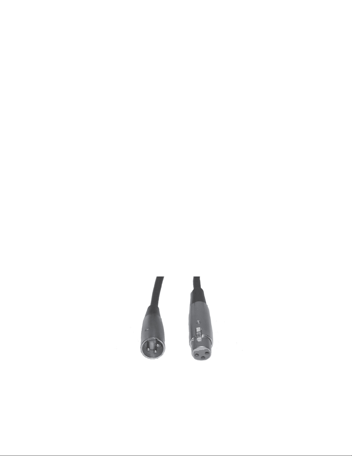
all pro lighting stores). Your cables should be made with a male XLR connector on one end and a
female XLR connector on the other. Also remember that DMX cable must be daisy chained and cannot
be split.
14
Page 15
DMX SETUP
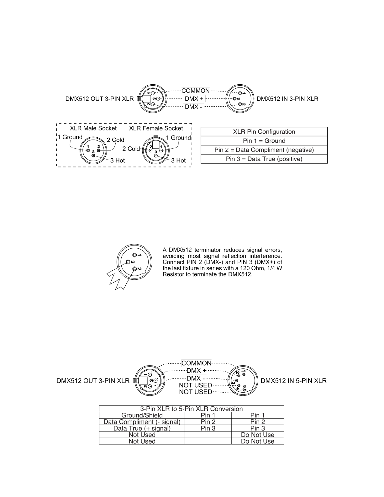
Notice: Be sure to the gures below when making your own cables. Do not use the ground lug on
the XLR connector. Do not connect the cable’s shield conductor to the ground lug or allow the shield
conductor to come in contact with the XLR’s outer casing. Grounding the shield could cause a short
circuit and erratic behavior.
Special Note: Line Termination. When longer runs of cable are used, you may need to use a terminator
on the last unit to avoid erratic behavior. A terminator is a 110-120 ohm 1/4 watt resistor which is connected between pins 2 and 3 of a male XLR connector (DATA + and DATA -). This unit is inserted in the
female XLR connector of the last unit in your daisy chain to terminate the line. Using a cable terminator
(ADJ part number Z-DMX/T) will decrease the possibilities of erratic behavior.
5-Pin XLR DMX Connectors: Some manufacturers use 5-pin DMX-512 data cables for DATA transmission in place of 3-pin. 5-pin DMX xtures may be integrated into a 3-pin DMX line with a 5-pin to
3-pin adapter cable. These adapters are readily available at most electronics stores. Follow the chart
below for a proper conversion.
15
Page 16
DMX SETUP
DMX Addressing:
All xtures should be given a DMX starting address when using a DMX controller, in order to ensure
that the correct xture responds to the correct control signal. This digital starting address is the channel
number from which the xture starts to “listen” to the digital control signal sent out from the DMX
controller. The assignment of this starting DMX address is achieved by setting the correct DMX address
on the digital control display on the xture.
You can set the same starting address for all xtures or a group of xtures, or set different addresses for
each individual xture. Setting all xtures to the same DMX address will cause all xtures to react in the
same way; in other words, changing the settings of one channel will affect all the xtures simultaneously.
If you set each xture to a different DMX address, each unit will start to “listen” to the channel number
you have set, based on the quantity of DMX channels of each xture. That means changing the settings
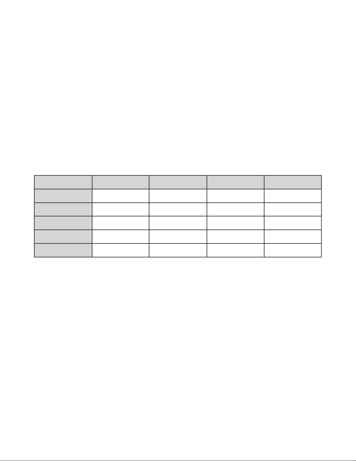
of one channel will only affect the selected xture. For instance, when this unit is set to 3 Channel
mode, you should set the starting DMX address of the rst unit to 1, the second unit to 4 (1 + 3), the
third unit to 7 (1 + 3 + 3), etc...
Channel Mode Unit 1 Address Unit 2 Address Unit 3 Address Unit 4 Address
3Ch 1 4 7 10
5Ch 1 6 11 16
9Ch 1 10 19 28
12Ch 1 13 25 37
18Ch 1 19 37 55
16
Page 17

DMX TRAITS
CHANNEL
3Ch 5Ch 9Ch 12Ch 18Ch
1 1 1 000 - 255 Red, 0% to 100%
2 2 2 000 - 255 Green, 0% to 100%
3 3 3 000 - 255 Blue, 0% to 100%
1 1 000 - 255 Red 1, 0% to 100%
2 2 000 - 255 Green 1, 0% to 100%
3 3 000 - 255 Blue 1, 0% to 100%
4 4 000 - 255 Red 2, 0% to 100%
5 5 000 - 255 Green 2, 0% to 100%
6 6 000 - 255 Blue 2, 0% to 100%
7 7 000 - 255 Red 3, 0% to 100%
8 8 000 - 255 Green 3, 0% to 100%
9 9 000 - 255 Blue 3, 0% to 100%
10 10 000 - 255 Red 4, 0% to 100%
11 11 000 - 255 Green 4, 0% to 100%
12 12 000 - 255 Blue 4, 0% to 100%
4 13
DMX
VALUES
000 - 015 No function
016 - 023 Red
024 - 031 Green
032 - 039 Blue
040 - 047 Red & Green
048 - 055 Green & Blue
056 - 063 Red & Blue
064 - 071 Red, Green, & Blue
072 - 079 Color 1
080 - 087 Color 2
088 - 095 Color 3
096 - 103 Color 4
104 - 111 Color 5
112 - 119 Color 6
120 - 127 Color 7
128 - 135 Color 8
136 - 143 Color Fade 1
144 - 151 Color Snake
152 - 159 Color Fade 2
160 - 167 Color Change
168 - 175 Color Flow 1
176 - 183 Color Flow 2
184 - 191 Color Flow 3
192 - 199 Color Flow 4
200 - 207 Color Flow 5
208 - 215 Color Flow 6
CONTINUED ON NEXT PAGE
FUNCTION
Color Macros and Programs
17
Page 18
DMX TRAITS
CHANNEL
3Ch 5Ch 9Ch 12Ch 18Ch
4 13
5 14
6 15 000 - 255 Strobing, slow to fast
7 16
4 8 17
5 9 18
DMX
VALUES
216 - 223 Color Flow 7
224 - 231 Color Flow 8
232 - 239 Color Flow 9
240 - 255 Sound Active
000 - 255 Master Dimmer, 0% to 100%
000 - 255 Program Speed, slow to fast
000 - 255 Sound Sensitivity, least sensitive to most sensitive
000 - 041 Standard
042 - 084 Stage
085 - 127 TV
128 - 170 Architectural
171 - 213 Theater
214 - 255 Default to unit curve setting
000 - 127 Light 1 off
128 - 255 Light 1 on
000 - 127 Light 2 off
128 - 255 Light 2 on
FUNCTION
Color Macros and Programs (continued)
Master Dimmer / Program Speed / Sound Sensitivity
Dimmer Curves
Light 1 (if applicable)
Light 2 (if applicable)
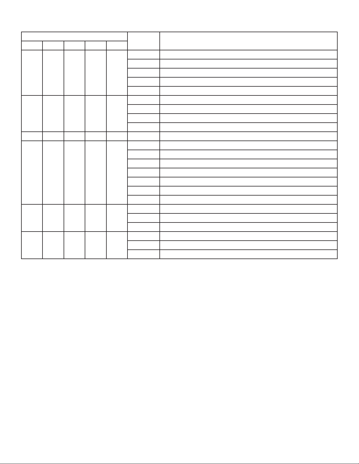
NOTES:
9-channel mode:
• When Channel 4 is set to values from 016 - 135, Channel 5 will control the dimming.
• When Channel 4 is set to values from 136 - 239, Channel 5 will control the speed of the programs.
• When Channel 4 is set to values from 240 - 255, Channel 5 will control sound sensitivity.
• If extra lights are attached to the top of the bar, Channels 8 & 9 will control the lights.
18-channel mode:
• When Channel 13 is set to values from 016 - 135, Channel 14 will control the dimming.
• When Channel 13 is set to values from 136 - 239, Channel 14 will control the speed of the pro-
grams.
• When Channel 13 is set to values from 240 - 255, Channel 14 will control sound sensitivity.
• If extra lights are attached to the top of the bar, Channels 17 & 18 will control the lights.
18
Page 19
PHOTOMETRIC CHART
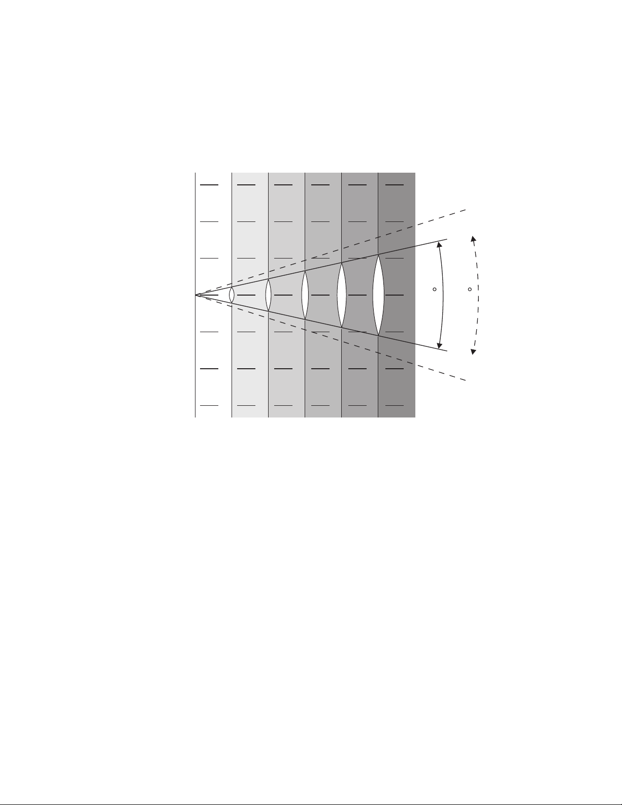
Beam angle 25°
Field angle 35°
Intensity(LUX)
Red LEDs
Green LEDs
Blue LEDs
Full LEDs
3
2
1
2400
2760
4130
8650
749
904
1357
2680
360
427
646
1345
206
249
96
372
138
161
246
506
0
25
35
1
Beam opening(m)
2
3
0 1 2 3 4 5
Diameter
25°
35°
(m)
Diameter
(m)
0.65
0.83
1.08
1.45
1.83
2.10
1.97
2.70
2.41
3.35
POWER CORD DAISY CHAIN
This feature allows the xtures to be linked via the IEC input and output sockets.
The maximum number of xtures that can be connected in this manner is as follows:
• 7 xtures maximum for 120V
• 14 xtures maximum for 230V
After this maximum number of xtures has been linked, a new power outlet must be used for any
additional xtures. All linked xtures should be of the same make and model type. DO NOT mix x-
tures.
19
Page 20
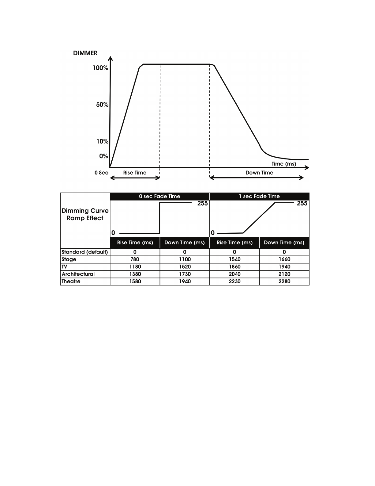
DIMMER CURVES
!
20
Page 21
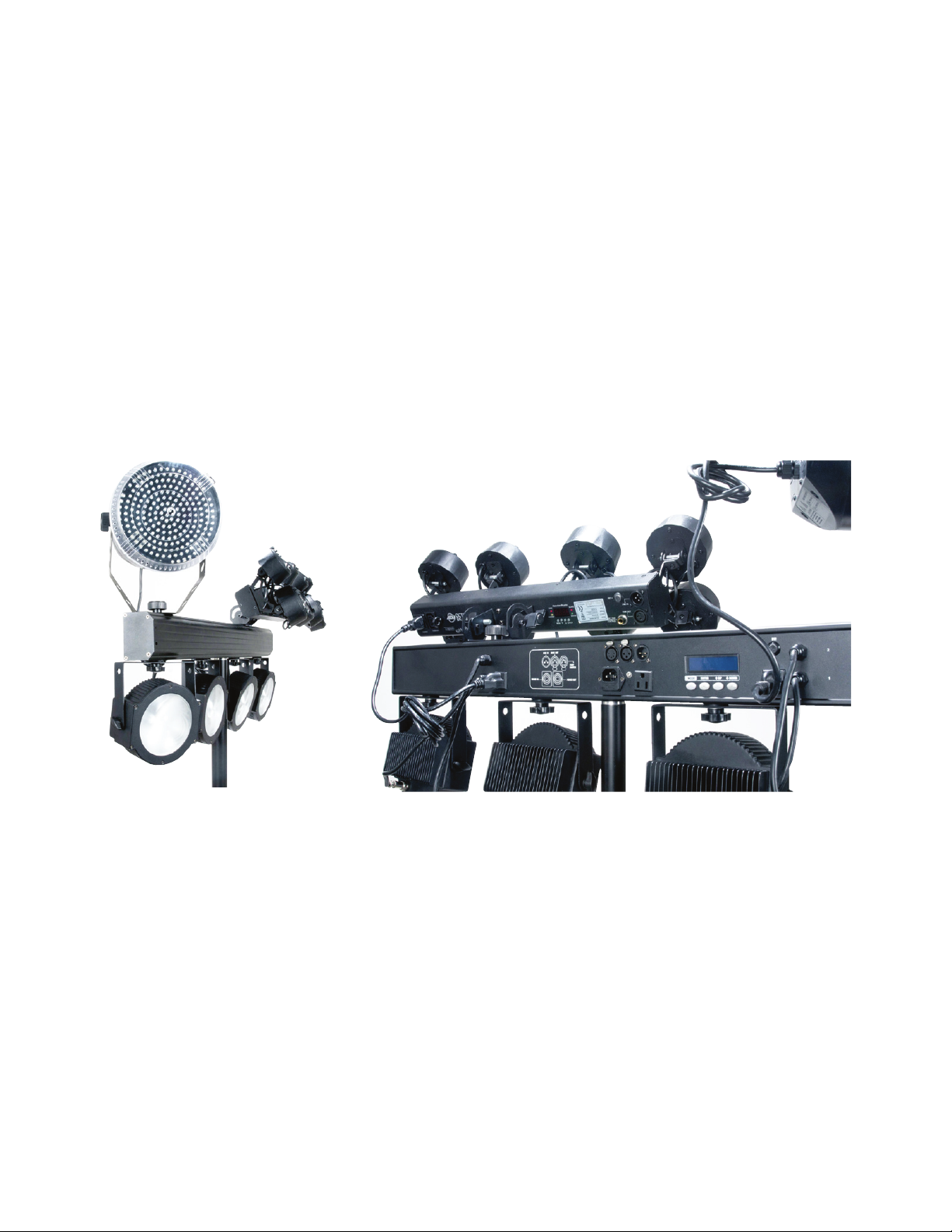
ALTERNATE LIGHTING INSTALLATION
One of this system’s special features is the ability to mount two light effects on top of the T-bar. These
lights can then be powered by plugging the power cords directly into the bar, with power sockets located on the right side and left side. There is also a middle power socket for power cord daisy chain-
ing only. Do not use the middle power socket to power your added lights.
To add the lights onto the top of the T-bar, rst make sure that the T-bar is secure and set up on the
stand correctly, then follow the instructions below.
1. Unscrew the black knob that is attached to the bolt.
2. Use the mounting bracket on the lighting effect to attach the lighting effect to the bolt on the T-bar.
3. Screw the black knob back in and tighten. See the sample pictures below.
4. Plug the mounted lights into their respective power jacks.
21
Page 22

FUSE REPLACEMENT
Locate and remove the unit’s power cord, then locate the fuse holder inside the power socket. Insert a
at-head screw driver into the power socket and gently pry out the fuse holder. Remove the bad fuse
and replace with a new fuse of the same rating. Please note that the fuse holder has a built-in socket
for a spare fuse. Make sure not to confuse the spare fuse for the active fuse.
CLEANING
Due to fog residue, smoke, and dust, cleaning the internal and external optical lenses must be carried
out periodically to optimize light output. Periodically use normal glass cleaner and a soft cloth to wipe
down the outside casing.
Cleaning frequency depends on the environment in which the xture operates (i.e. smoke, fog residue,
dust, dew).
TROUBLE SHOOTING
Listed below are a few common problems the user may encounter, with possible solutions.
Unit does not respond to DMX:
Check that the DMX cables are connected and wired correctly (pin 3 is “hot”; on some other DMX
devices pin 2 may be “hot”). Also, check that all cables are connected to the right connectors, as the
order in which the inputs and outputs are connected can affect the operation of the device.
Unit does not respond to sound:
• Quiet or high pitched sounds will not activate the unit.
• Make sure that Sound Active mode is activated.
22
Page 23

SPECIFICATIONS
• COB LED Par Wash System with 4 Par xtures
• COB Technology (Chip On Board) produces powerful, smooth RGB color mixing with rich palettes
of color
• Smooth RGB Color Mixing (fast or slow color change operation)
• Great for Stage Lighting, Bands, Night Clubs & Mobile Entertainers
• Emits less heat on performers on stage as opposed to conventional stage lighting
• 4 Operational modes: Sound Active, Auto Run, Built-In Programs, & DMX-512
• Stand Alone or Primary/Secondary Conguration
• Pixel Flip option changes pixel orientation
• 14 Built-in Programs
• 5 DMX Channel modes: 3, 5, 9, 12 and 18 channels
• Digital DMX Display with 4-button menu for easy navigation
• 3-Pin DMX In/Out
• With Wired Digital Communication Network
• Strobe & Pulse LED Effect
• Electronic Dimming: 0-100%
• 5 selectable Dim Curves (Standard, Stage, TV, Architectural & Theatre)
• Beam angle: 90-degree
• Includes 25-degree beam angle lens kit
• Long Life LEDs (Rated at approximately 50,000 hrs.)
• Foot Controller Features: Mode, Black Out and Program Change
• RF Remote Control control up to 25 meters
• Light Source: Each xture has 1x 30-Watt TRI Color COB LEDs
• LUX @ 3M: 1345
• Refresh Rate: 3.6KHz
• Power Draw: 144W Max (entire system)
• 2x power plugs on rear or plug in other lighting xtures (120V = Edison, 230V = Shuko)
• Includes hardware to mount lighting xtures on top of bar
• Multi-voltage operation: AC 100V-240V 50/60Hz (IEC Input)
• Dimensions (LxWxH): 39.5” x 12.75”x 3.25”/ 1000 x 320 x 82mm
• Weight: 35 lbs./ 16 kg. (Fixture Bar, Stand & Controller)
• Maximum stand height: 9 feet
• CE Certied
23
Page 24

 Loading...