

Page 1
2-Wire
EVD2-10KIT
Video Intercom
System
Read this manual carefully before using the product, and keep it well for future use.
USER
MANUAL
Page 2

Page 3
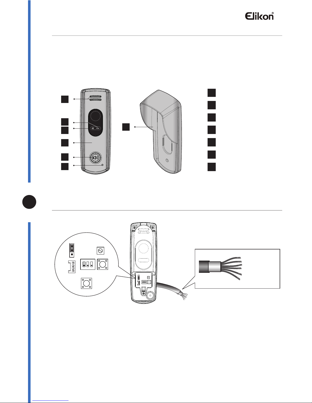
Parts and Function
The door station is an audio door station without camera,which is designed for DT 2-wire system.
The front panel is made of zinc alloy for better protection against vandalism & cauterization, and
the call button is also made of zinc alloy with blue backlight for auxiliary illumination, the unlock
and talking LED indicator guarantee the door station working efficiently.
With the rainy cover, the door station can be strongly protection against water.
◆ Lock Control Jumper: to select the lock type. Please refer to Electric Lock Connection
◆ DIP switch: to set ID code for door station, total 4 door stations can be supported. Please
refer to DIP Switch Setting.
◆ SPK adjust: to adjust the talk volume.
◆ PROG button: reserve.
◆ CALL button: press to call the user.
◆ 4P terminal: to update software via specified programmer.
◆ Connection line: to connect the bus line and the electronic locks.
BUS(Blue&Green):
connect to the bus line, no polarity.
S2+(Red): the S2+ connect with S1- to activate the relay of ERL to extend a camera of DT-CAM,
Unit Mounting
The location of outdoor station should keep away from snow,rain,and intensity light.
Accessory contents:
Accessories include a screwdriver T20, one M4X10 screw, two PA4X25 screws,three PA3x25
screws,three PM3x12 screws,and five screw stoppers Φ6X30.
Installation steps:
Installation height for door station usually is 145~160cm.
1. Use screws to fix the back panel and rainy cover to the wall after connect the cable correctly.
2. Attach the front panel to the back panel, then use the screw to fix it.
Wiring and Connection
Basic one-to-one connecon
Terminal Description
Speaker
Talk Indicator
Unlock Indicator
Call Button
Front Panel
Microphone
1
2
3
4
7
5
6
1
2
3
4
5
6
Rainy Cover
7
PM3*12
Bus PL S2+ S1+ S1-
BUS(Blue&Green); S2+(Red); PL(White); S1+(Yellow); S1-(Black);
1 2 3
ON
1 2 3
1 2
3
ON
1 2 3
BUS(Blue&Green)
S2+(Red)
PL(White)
S1+(Yellow)
S1-(Black)
4P
terminal
DIP PROG
SPK adjust
Lock Control
Jumper
Connection line
CALL button
please refer to DT-CAM user instructions in details.
PL(White): external lock power input, connect to the power positive(power +).
S1+(Yellow): lock power(+) output.
S1-(Black): lock power(-) output.
-3-
Page 4
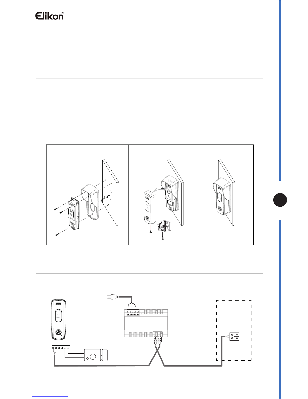
Unit Mounting
The location of outdoor station should keep away from snow,rain,and intensity light.
Accessory contents:
Accessories include a screwdriver T20, one M4X10 screw, two PA4X25 screws,three PA3x25
screws,three PM3x12 screws,and five screw stoppers Φ6X30.
Installation steps:
Installation height for door station usually is 145~160cm.
1. Use screws to fix the back panel and rainy cover to the wall after connect the cable correctly.
2. Attach the front panel to the back panel, then use the screw to fix it.
Wiring and Connection
Basic one-to-one connecon
M4*10
PM3*12
1 2 3
-
+
Monitor
Bus PL S2+ S1+ S1-
BUS(Blue&Green); S2+(Red); PL(White); S1+(Yellow); S1-(Black);
AC~
PC6
please refer to DT-CAM user instructions in details.
PL(White): external lock power input, connect to the power positive(power +).
S1+(Yellow): lock power(+) output.
S1-(Black): lock power(-) output.
-4-
Page 5
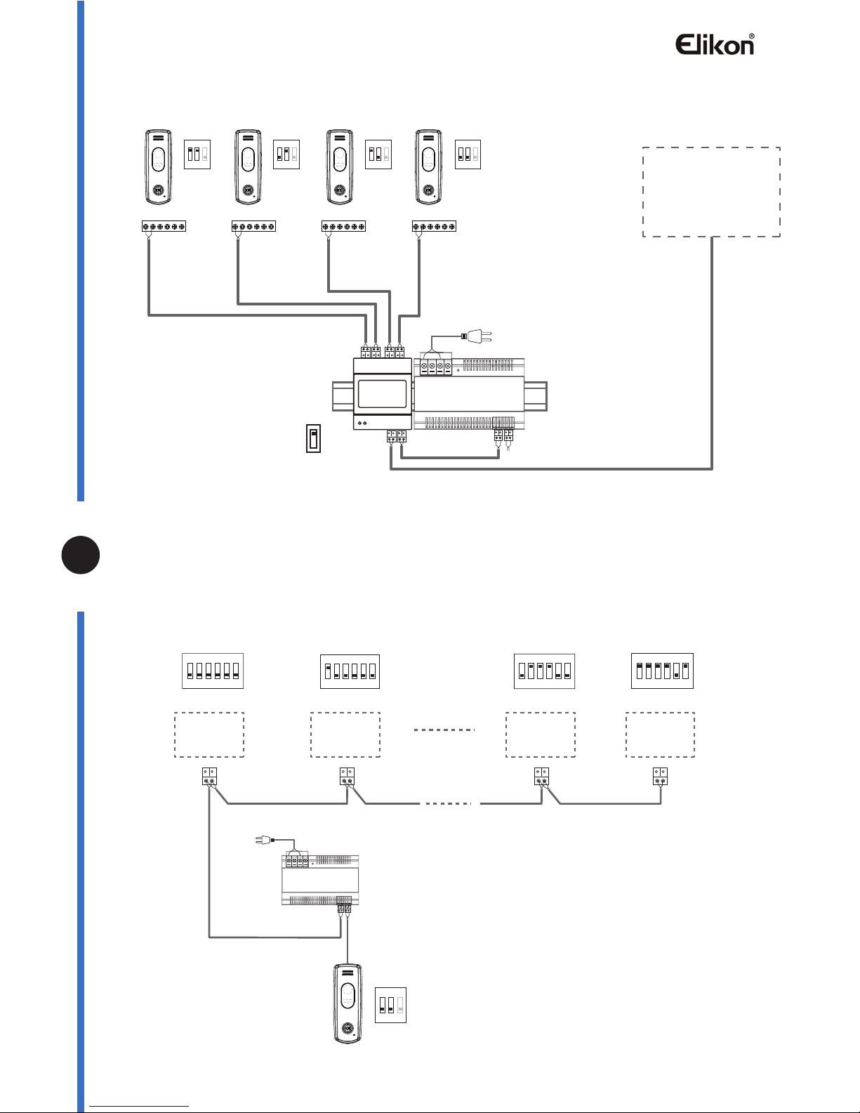
Mul Door Staon Connecon
Multi Monitors Connection
Basic IN-OUT wiring mode
With DBC-4S Wiring Mode
Monitors
1 2 3
ON
1 2 3
ON
1 2 3
ON
1 2 3
ON
1# Camera
DIP=on,off,off
ID=00
ID=10
ID=01ID=11
2# Camera3# Camera4# Camera
DBC-4S
A B C D
OFF
ON
Impedance
Switch
Bus PL S2+ S1+ S1- Bus PL S2+ S1+ S1- Bus PL S2+ S1+ S1- Bus PL S2+ S1+ S1-
BUS(Blue&Green); S2+(Red); PL(White); S1+(Yellow); S1-(Black);
1 2 3
ON
ID=00
monitor monitor monitor monitor
Code=0, DIP-6=off
1 2 3 4 5 6
ON
Code=1, DIP-6=off
1 2 3 4 5 6
ON
1 2 3 4 5 6
ON
1 2 3 4 5 6
ON
Code=3, DIP-6=on
Code=1, DIP-6=on
Code=15, DIP-6=on
Code=13, DIP-6=on
AC~
PC6
AC~
PC6
Code=14, DIP-6=off
1 2 3 4 5 6
ON
Code=15, DIP-6=on
1 2 3 4 5 6
ON
1 2 3 4 5 6
ON
1 2 3 4 5 6
ON
-5-
Page 6
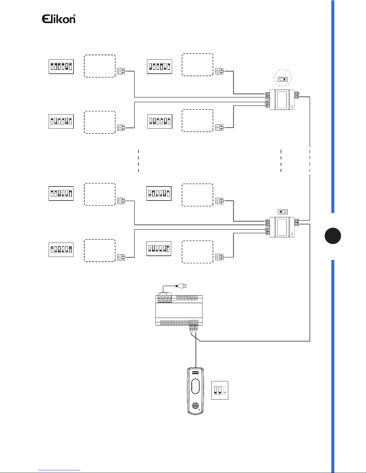
With DBC-4S Wiring Mode
1 2 3 4 5 6
ON
1 2 3 4 5 6
ON
Code=3, DIP-6=on
Code=1, DIP-6=on
1 2 3 4 5 6
ON
1 2 3 4 5 6
ON
Code=2, DIP-6=on
Code=0, DIP-6=on
Code=15, DIP-6=on
Code=13, DIP-6=on
Code=14, DIP-6=on
Code=12, DIP-6=on
OFF ON
OFF ON
monitor
monitor
monitor
monitor
monitor
monitor
monitor
monitor
DBC-4S
A B C D
DBC-4S
A B C D
Impedance
switch
Impedance
switch
DIP=on,off,off
DIP=on,off,off
1 2 3
ON
ID=00
AC~
PC6
1 2 3 4 5 6
ON
1 2 3 4 5 6
ON
1 2 3 4 5 6
ON
1 2 3 4 5 6
ON
-6-
Page 7
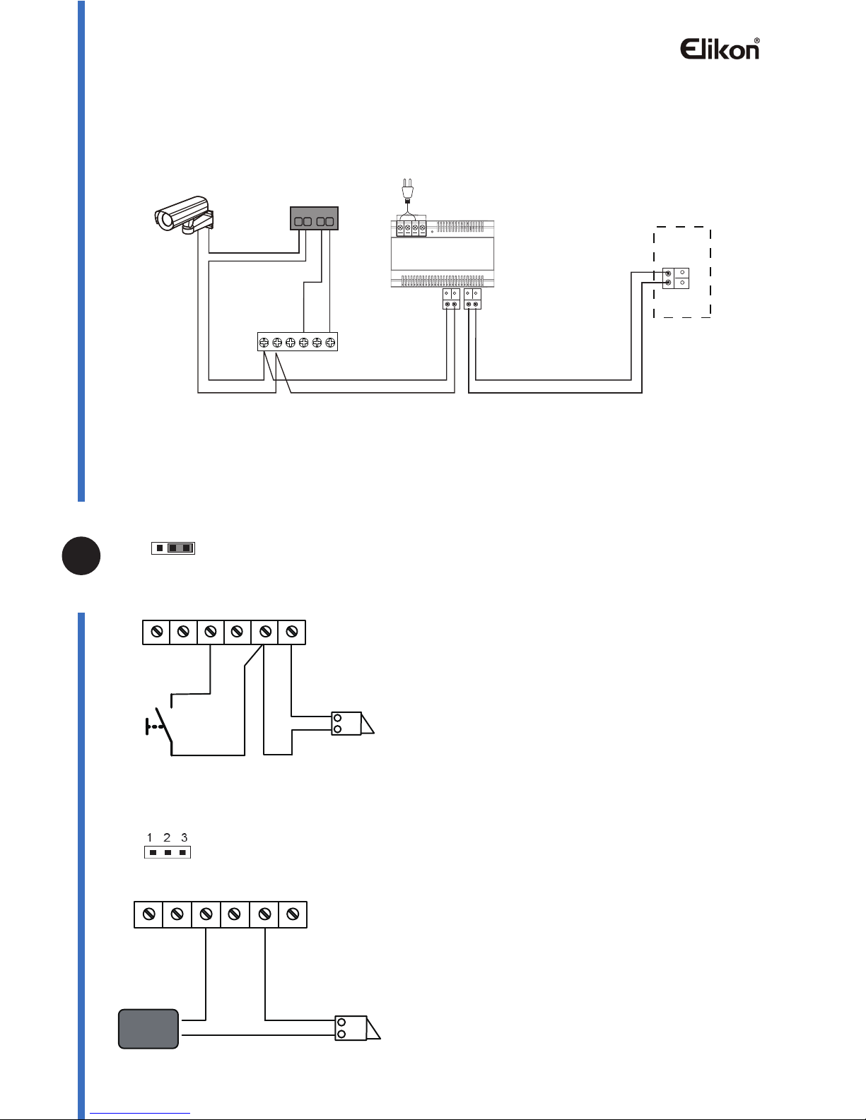
With DT-CAM wiring mode
Electric Lock Connecon
Door Lock Controlled with Internal Power
Door Lock Controlled with Dry Contact
Note:
1. Electronic lock of Power-on-to-unlock type
should be used.
2. The door lock is limited to 12V, and holding
current must be less than 250mA.
3. The door lock control is not timed from Exit
Button(EB).
4. The Unlock Mode Parameter of Monitor must
be set to 0 (by default).
EB
*
LOCK
Jumper position in
Connect one lock
2-3
Bus PL S2+ S1+ S1-
Note:
1. The external power supply must be used
according to the lock.
2. The jumper must be taken off before connecting.
3. Setup the Unlock Mode of Monitor for different
lock types.
* Power-on-to-unlock type:Unlock Mode=0 (by default)
* Power-off-to-unlock type:Unlock Mode=1
DIP Switch Setting
The DIP switch is designed to set the code for door station and monitor, there are two states for
each DIP switch, please refer to the following sketch map.
The audio door station DT595A can be extended an additional CCTV camera to be a video door
station. For more details about the camera, please refer to DT-CAM user instructions.
Door station DIP setting
Indoor monitor DIP setting
Bit state Description
ON(1)
ON
Total 3 bits can be configured, bit-1 and bit-2 are used to assign ID code for door station, bit-3 is
used to match the video impedance.The switches can be modified either before or after installation.
There are 6 bits in total. The DIP switches are used to configure the user code for Monitors.
Bit-6 is an video impedance match switch, which have to be set to ON if match the impedance,
otherwise set to OFF.
Bit-1~Bit-5 are used to set user code, to DT595A door station, the user code should set to 0~15.
Please refer to the following settings:
Note: if the video impedance need to match, please set the bit-3 on.
1
2 3
ON
1
2 3
ON
1
2 3
ON
1
2 3
ON
LOCK
Take off the Jumper
POWER
SUPPLY
Bus PL S2+ S1+ S1-
1 2 3
AC~
PC6
ERL
DT595A
DT-CAM
DS IM
Bus PL S2+ S1+ S1-
OUT IN
Monitor
-7-
Page 8
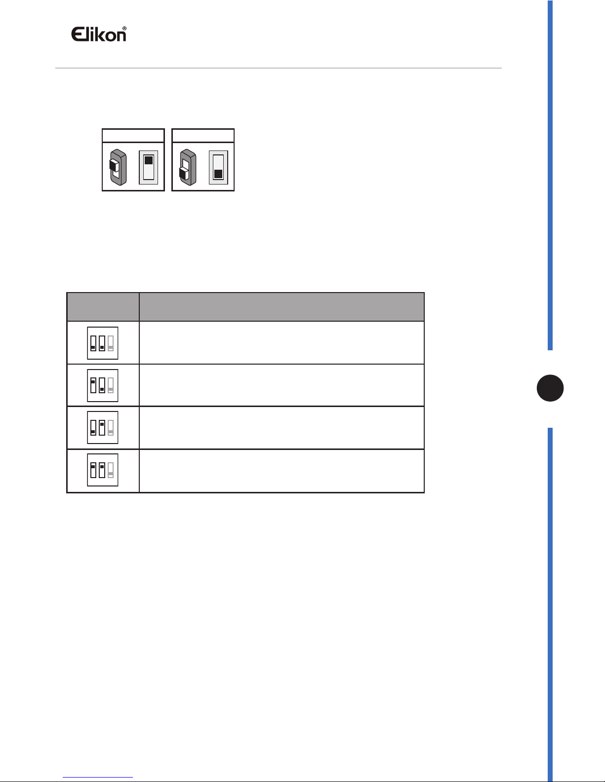
DIP Switch Setting
The DIP switch is designed to set the code for door station and monitor, there are two states for
each DIP switch, please refer to the following sketch map.
Door station DIP setting
Indoor monitor DIP setting
Bit state Description
ON(1)
=
OFF(0)
=
ON
ON
Total 3 bits can be configured, bit-1 and bit-2 are used to assign ID code for door station, bit-3 is
used to match the video impedance.The switches can be modified either before or after installation.
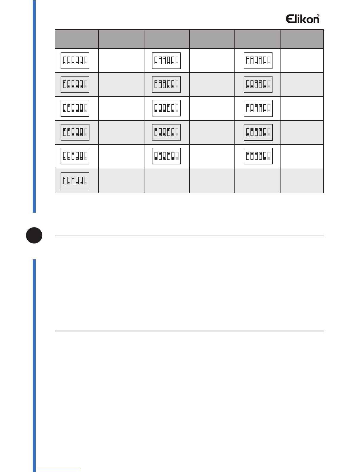
There are 6 bits in total. The DIP switches are used to configure the user code for Monitors.
Bit-6 is an video impedance match switch, which have to be set to ON if match the impedance,
otherwise set to OFF.
Bit-1~Bit-5 are used to set user code, to DT595A door station, the user code should set to 0~15.
Please refer to the following settings:
Note: if the video impedance need to match, please set the bit-3 on.
1
2 3
ON
1
2 3
ON
1
2 3
ON
1
2 3
ON
ID = 0(00), set to the first door station
ID = 1(10), set to the second door station
ID = 2(01), set to the third door station
ID = 3(11), set to the fourth door station
-8-
Page 9
When Monitor quanty < 20
When Monitor quanty >20
Bit state User code
code=0
code=1
code=2
code=3
code=4
code=6
code=7
code=8
code=9
code=10
code=11
code=12
code=13
code=14
code=15
code=5
Bit state User code Bit state User code
Cable Requirements
The maximum distance of the wiring is limited in the DT system. Using different cables may also
affect the maximum distance which the system can reach.
Specification
• Power Supply:DC 24V
• Power Consumption:Standby 60mA; Working status 200mA
• Lock Power Supply:12Vdc, 300mA(Internal Power)
• Working Temperature:
-10ºC ~ +45ºC
• Wiring: 2 wires,non-polarity
• Dimension:137(H)x49(W)x28(D)mm
Precaustions
• Please clean the unit with soft cotton cloth, don't use the organic impregnant or chemical clean agent.
If necessary, please use a little pure water or dilute soap water to clean the dust.
• The unit is weather resistant. However do not spray high pressure water on access control keypad
directly. Excessive moisture may cause problems with the unit.
• You must use the right adaptor which is supplied by the manufacture or approved by the manufacture.
• Pay attention to the high voltage inside the products, please refer service only to a trained and qualified
professional.
Cable Usage A B C
Twisted cable 2x0.75 mm
Twisted cable 2x1 mm
Cable Usage A B C
Twisted cable 2x1 mm
Twisted cable 2x1.5 mm
1 2 3 4 5 6
ON
1 2 3 4 5 6
ON
1 2 3 4 5 6
ON
1 2 3 4 5 6
ON
1 2 3 4 5 6
ON
1 2 3 4 5 6
ON
1 2 3 4 5 6
ON
1 2 3 4 5 6
ON
1 2 3 4 5 6
ON
1 2 3 4 5 6
ON
1 2 3 4 5 6
ON
1 2 3 4 5 6
ON
1 2 3 4 5 6
ON
1 2 3 4 5 6
ON
1 2 3 4 5 6
ON
1 2 3 4 5 6
ON
Note:If the monitor has been specified
the distance,refer to the parameter.
-9-
Page 10
When Monitor quanty < 20
When Monitor quanty >20
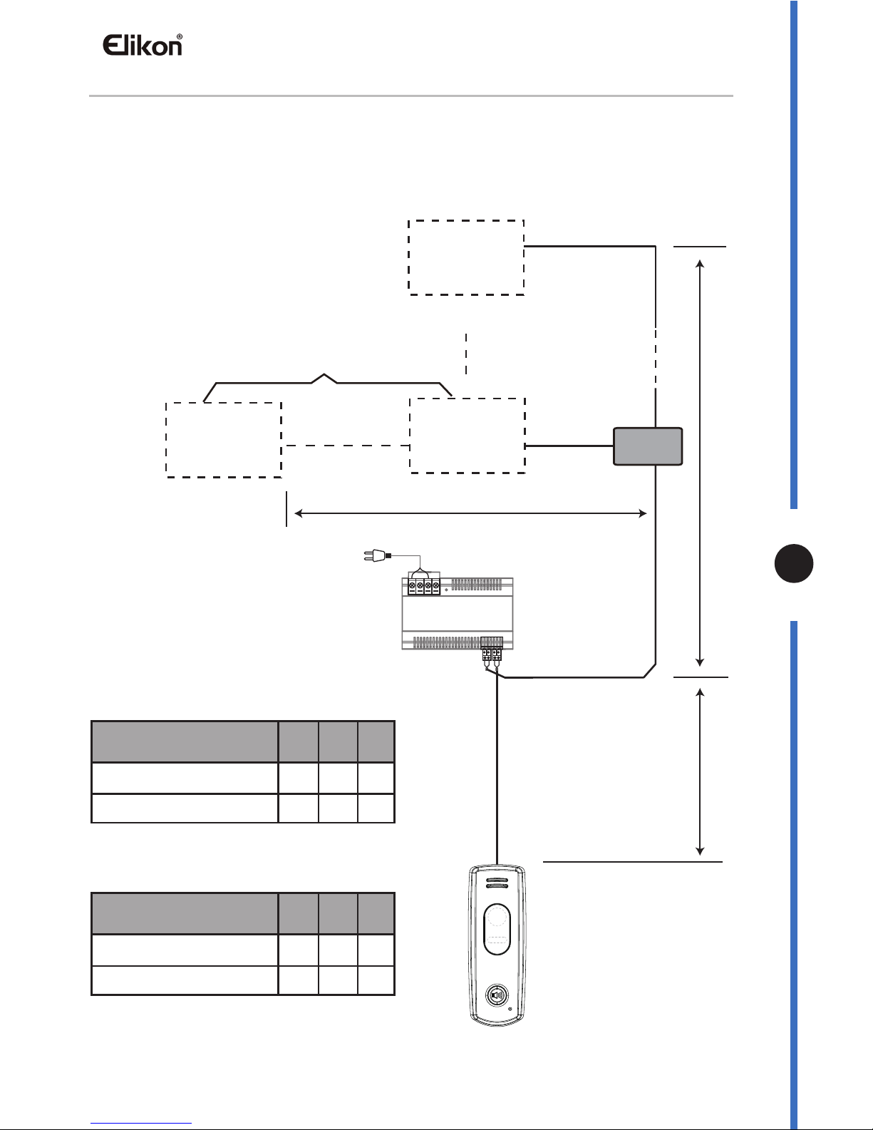
Cable Requirements
The maximum distance of the wiring is limited in the DT system. Using different cables may also
affect the maximum distance which the system can reach.
Cable Usage A B C
Twisted cable 2x0.75 mm
2
60 60 30
80 80 40
Twisted cable 2x1 mm
2
Cable Usage A B C
Twisted cable 2x1 mm
2
70 30 20
70 50 30
Twisted cable 2x1.5 mm
2
The farest monitor
B
A
C
DBC-4S
monitor
monitor
monitor
with two or four monitors
AC~
PC6
Note:If the monitor has been specified
the distance,refer to the parameter.
-10-
Page 11

Page 12
The design and specications can be changed without notice to the user. Right to
interpret and copyright of this manual are preserved.
EVD2-10KIT
 Loading...