

Page 1

ikon
User Manual
2-Wire System
Model: EVD2-CC4C
Camera Interface
EVD2-CC4C
Power In-Use
CAM(1~4)
Please read this manual carefully before using the product you
purchase, and keep it well for future use.We reserve the right to
modify the specication in this manual at any time without notice.
CAM1 CAM2
CAM3 CAM4
Page 2
ikon
EVD2-CC4C
1.About EVD2-CC4C Unit
Description:
The camera interface EVD2-CC4C is a controller function device designed
for Elikon system to control camera. In addition, EVD2-CC4C can be
configured as camera converter working mode to fit before used distribuide
camera accessory of the project. For details, see later section 5.
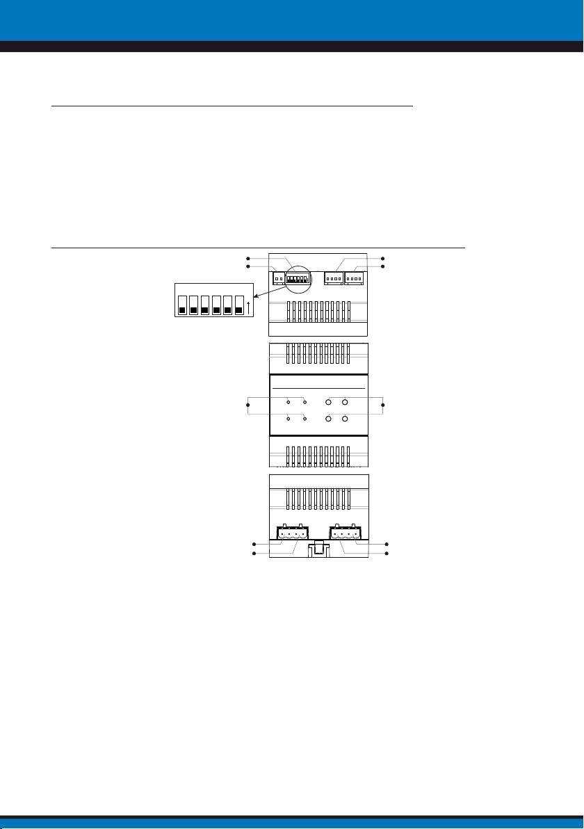
Terminal Description
2.
DIP
RS485
ON
123456
ON
123456
CAM1
CAM2
2-Wire System
INDICATORS BUTTONS
BUS(IN)
BUS(OUT)
Model: EVD2-CC4C
Power In-Use
CAM(1~4)
Camera Interface
CAM1 CAM2
CAM3 CAM4
CAM4
CAM3
RS485:Reserved.
CAM1~2:Connect to
CAM3~4:Connect to
regular analog CCTV(the following called TYPE A Camera)
2 wire camera(the following called TYPE B Camera ); If
you want to connect CCTV to this port, it must be connected camera converter,
then the port can work usually(The camera converter is used to transform the 2
wire camera to analogue camera,for details, see camera converter manual
BUS(IN):
Connect to the bus line, no polarity.
).
BUS(OUT):Connect to the bus line, no polarity.
BUTTONS:Press CAM1~CAM4 button, it can control the corresponding
video output.
.
-1-
Page 3
ikon
EVD2-CC4C
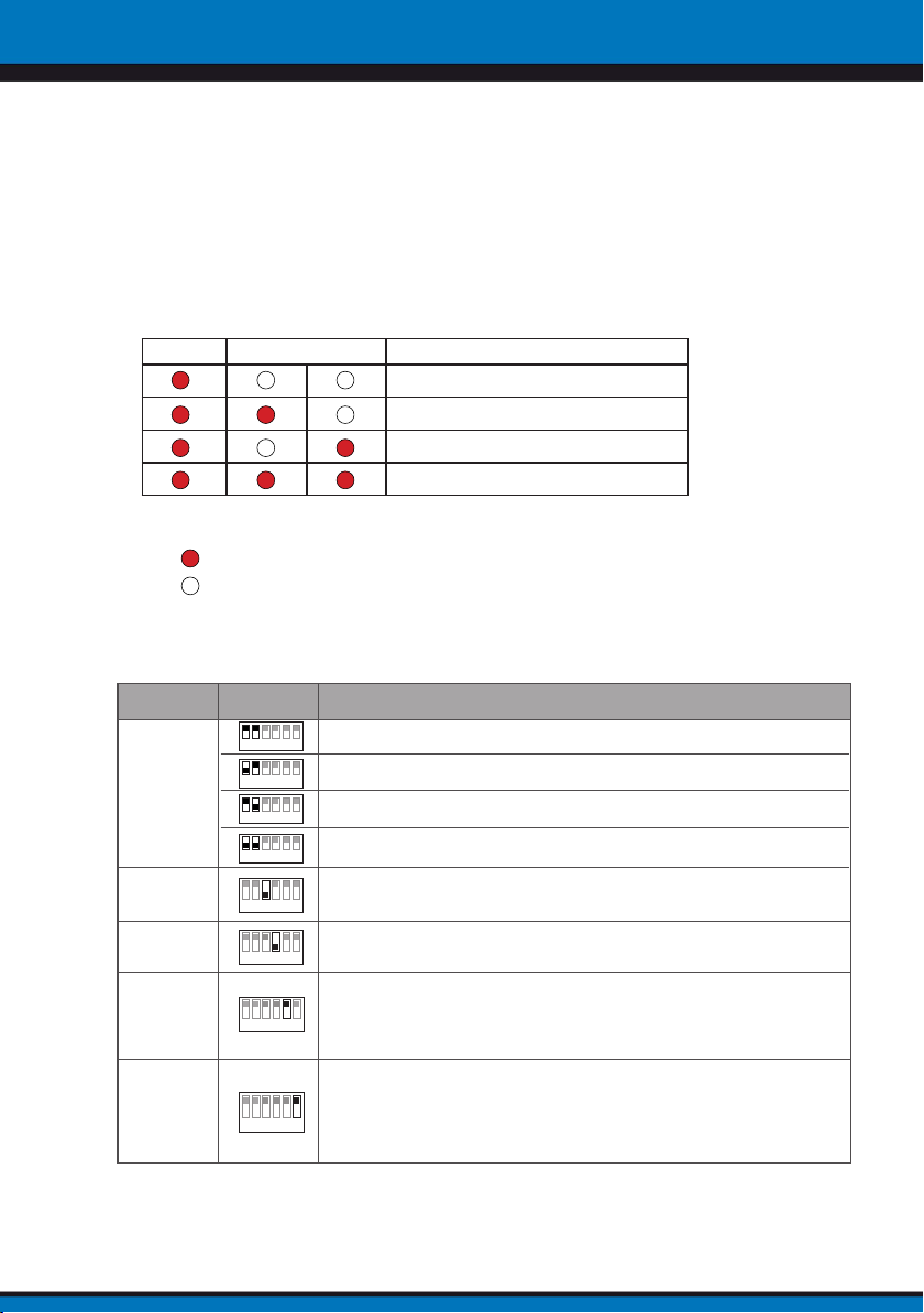
INDICATORS:
1.Power: Working indicator, always on when the EVD2-CC4C work normally.
2.In-Use:Video output indicator, always on when the EVD2-CC4C output the video.
3.CAM(1~4):Video output indicator.
In-Use CAM(1~4) Description
CAM1 video output
CAM2 video output
CAM3 video output
CAM4 video output
NOTE:
*
:It shows that the indicator ON;
:It shows that the indicator OFF.
DIP:DIP switches.
Bit
DIP1~DIP2
DIP3
DIP4
DIP5
DIP6
Bit State Description
1 2 3 4 5 6
ON
1 2 3 4 5 6
ON
1 2 3 4 5 6
ON
1 2 3 4 5 6
ON
1 2 3 4 5 6
ON
1 2 3 4 5 6
ON
1 2 3 4 5 6
ON
set to the first EVD2-CC4C.
set to the second EVD2-CC4C.
set to the third EVD2-CC4C.
set to the fourth EVD2-CC4C.
TYPE A Camera used. When EVD2-CC4C connected TYPE A Camera, it
should be set to ON.
TYPE B Camera used. When EVD2-CC4C connected TYPE B Camera, it
should be set to ON.
When all EVD2-CC4C of the system are configured to connect the two
cameras(two TYPE A Cameras or two TYPE B Cameras ), it should be set to ON
When all EVD2-CC4C of the system are configured to connect the four
cameras(two TYPE A Cameras and two TYPE B Cameras ), it should be set to
OFF.
When the system connected programer, and
cameras(the two cameras of the device is valid),it should be set to ON;
1 2 3 4 5 6
ON
When the system don’t connected programer(or connected programer, but
programer don’t connected camera), it should be set to OFF.
-2-
programer connected two
Page 4
ikon
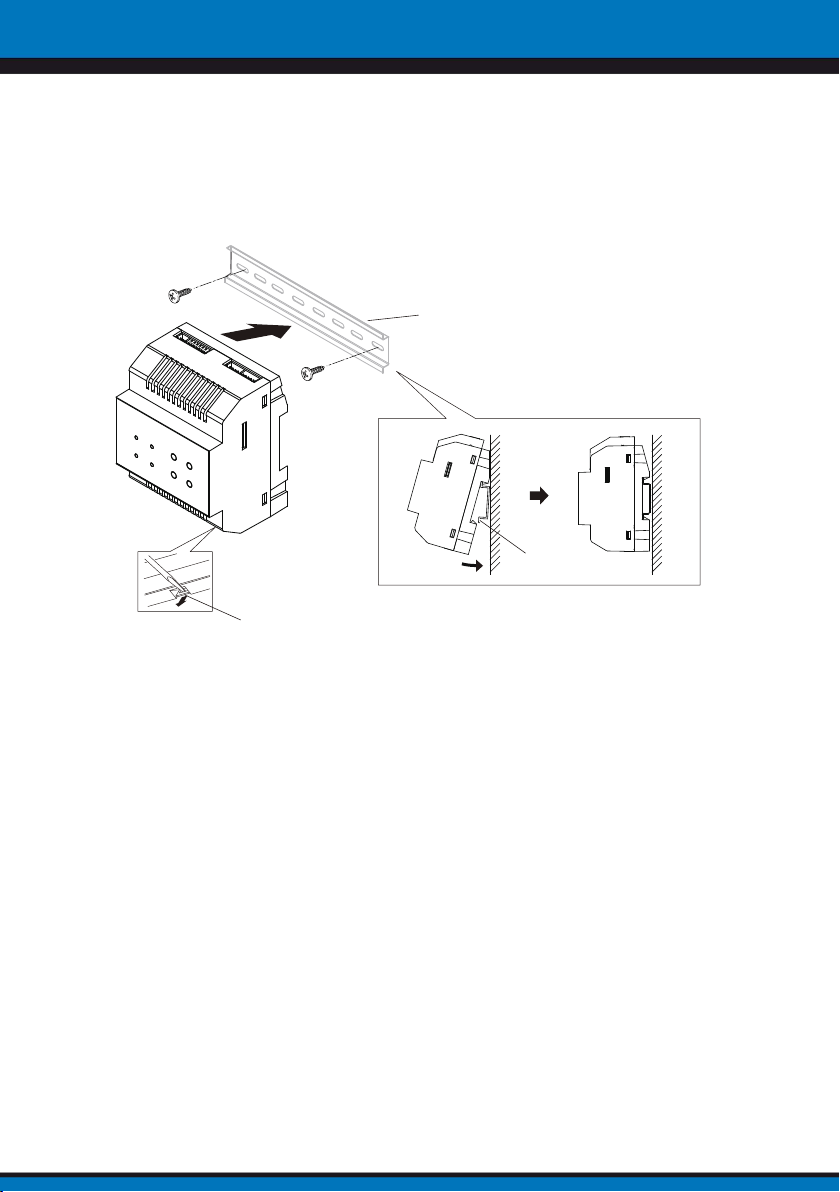
3. Unit Mounting
Mounting Buckle
Din rail
EVD2-CC4C
Step1: Mount the din rail to
the wall with screws ;
Step2: Pull down the
mounting buckle,then hang
the unit on din rail.
Din rail
-3-
Page 5
ikon
EVD2-CC4C
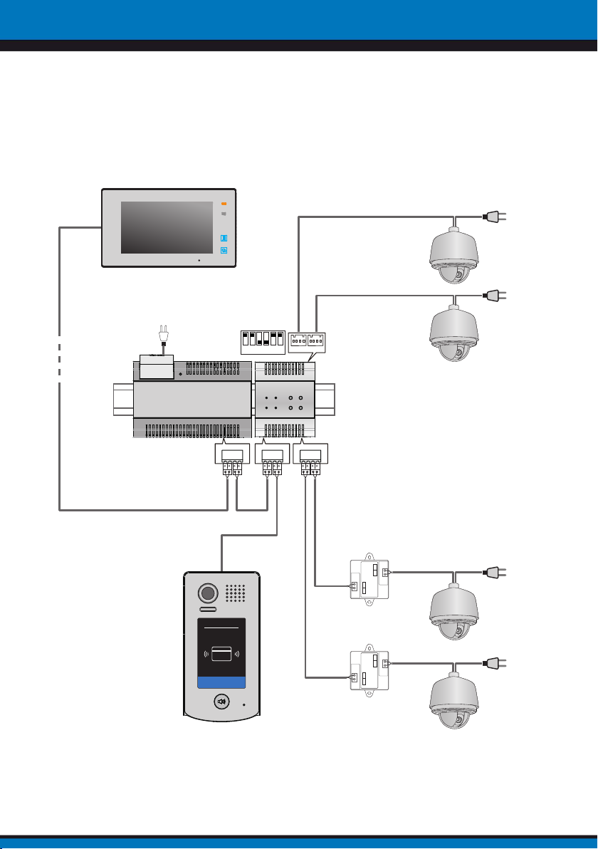
4. Wiring Diagram
4.1 Single door station and single EVD2-CC4C applications:
AC~
1 2 3 4 5 6
ON
1# CCTV
2# CCTV
EVD2-624
BUS(IM) BUS(DS)
RF CARD
EVD2-CC4C
BUS(IN) BUS(OUT)
VEDIO
GND
2-WIRE SYSTEM
GND VIDEO
Camera
DT-CCU
BUS
BUS BUS
4# CCTV
VEDIO
GND
2-WIRE SYSTEM
GND VIDEO
Camera
DT-CCU
BUS
BUS BUS
3# CCTV
-4-
Page 6
ikon
EVD2-CC4C
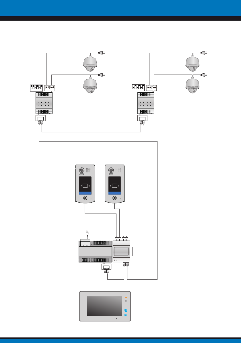
4.2 Multi door station and two EVD2-CC4C (connected two
Cameras
) applications:
TYPE A
1 2 3 4 5 6
ON
EVD2-CC4C
BUS(IN) BUS(OUT)
1# CCTV
2# CCTV
a b
(Device Address:1) (Device Address:0)
RF CARD
AC~
RF CARD
1 2 3 4 5 6
ON
EVD2-CC4C
BUS(IN) BUS(OUT)
3# CCTV
4# CCTV
EVD2-CC4C
BUS(IM) BUS(DS)
A B C D
EVD2-OD4C
-5-
Page 7
ikon
EVD2-CC4C
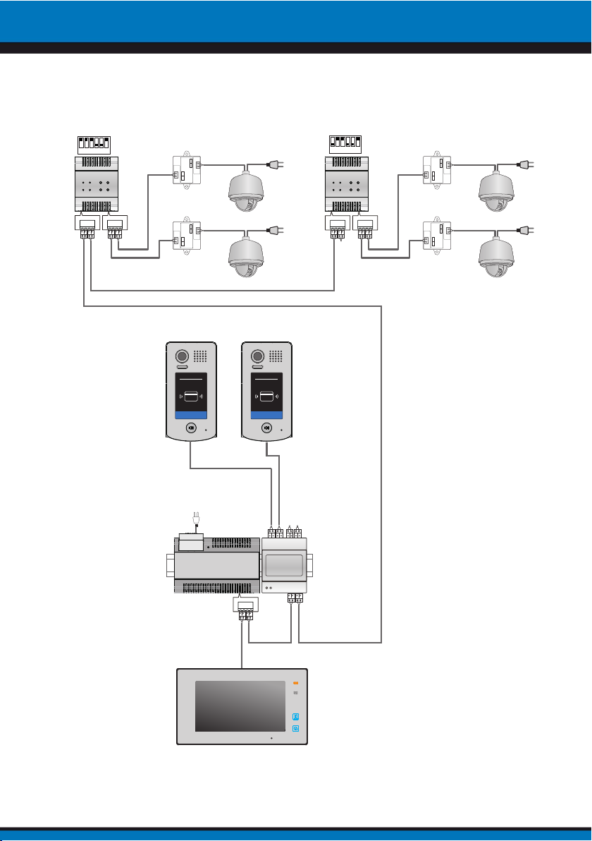
4.3 Multi door station and two EVD2-CC4C (connected two
Cameras
1 2 3 4 5 6
ON
EVD2-CC4C
) applications:
1 2 3 4 5 6
VEDIO
GND
2-WIRE SYSTEM
GNDVIDEO
Camera
CONVERTER
BUS
a b
BUSBUS
2# CCTV
ON
EVD2-CC4C
TYPE B
VEDIO
GND
2-WIRE SYSTEM
GNDVIDEO
Camera
CONVERTER
BUS
BUSBUS
4# CCTV
BUS(IN) BUS(OUT)
VEDIO
GND
2-WIRE SYSTEM
GNDVIDEO
Camera
CONVERTER
BUS
BUSBUS
1# CCTV
(Device Address:1) (Device Address:0)
RF CARD
AC~
RF CARD
A B C D
EVD2-624
EVD2-OD4C
BUS(IM) BUS(DS)
BUS(IN) BUS(OUT)
VEDIO
GND
2-WIRE SYSTEM
GNDVIDEO
Camera
CONVERTER
BUS
BUSBUS
3# CCTV
NOTE: The system can connect programer(programer connected two
Cameras
), but at this time, the DIP6 of EVD2-CC4C must be set to ON.
-6-
TYPE B
Page 8
ikon
EVD2-CC4C
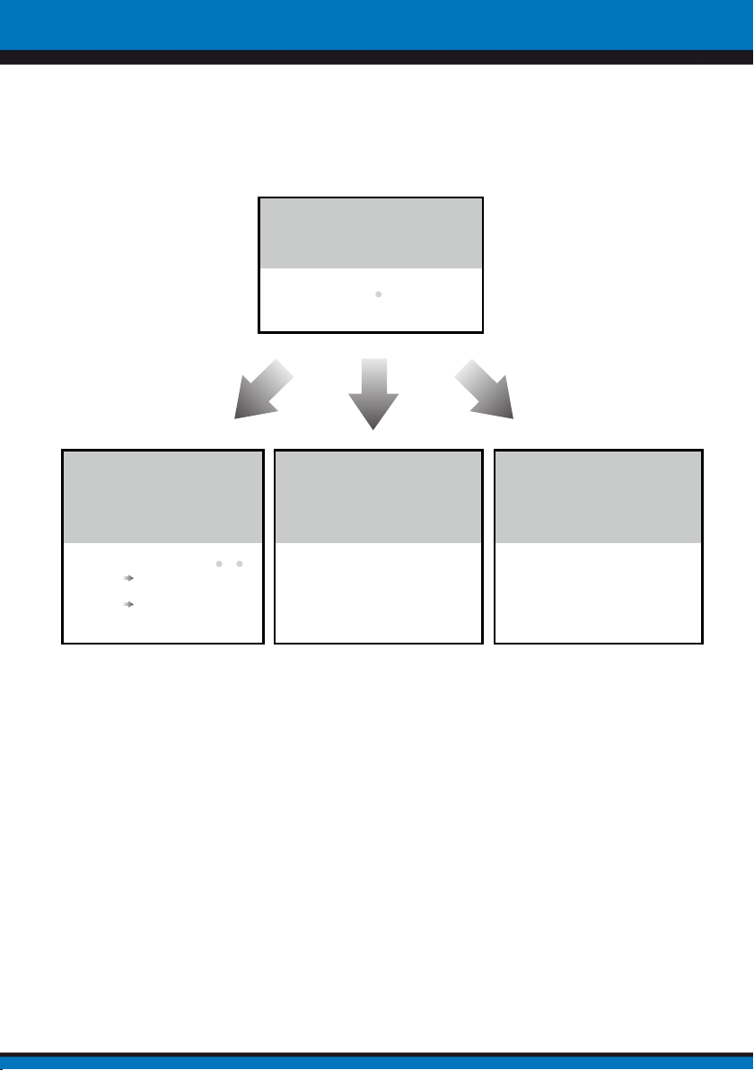
2).Working mode configuration, the camera switching time setting, and
monitoring time setting.
In the standby, press and hold
"CAM4" button for 3 seconds, it will
enter the state of program.
indicator:IN-USE
(ash)
In the program state, press and
hold "CAM1" button for 3 seconds
to switch the working mode. Then
it will return to standby
Working mode indicator:CAM(1~4)
[SCU mode] [DCU mode]:
[DCU mode] [SCU mode]:
(ash once)
(ash twice)
In the program state, press
and hold "CAM2" button for 3
seconds, it will enter the state of
camera switching time setting.
(1)the left light of indicator CAM (1 ~ 4)
starts ashing (ash once per second);
(2)Flash once to increase 3 seconds;
(3)Press any button to conrm the
setting and return to standby.
Note:
1. The maximum can be set to
99 seconds, to 99 seconds, then
automatically save and return to standby.
2. 6 seconds by default.
In the program state, press
and hold "CAM3" button for 3
seconds, it will enter the state of
monitoring time setting.
(1)the right light of indicator CAM (1 ~ 4)
starts ashing (ash once per second);
(2)Flash once to increase 15 seconds;
(3)Press any button to conrm the
setting and return to standby.
Note:
1. The maximum can be set to 900
seconds, to 900 seconds, then
automatically save and return to standby.
2. 600 seconds by default.
Note:In program state, if there isn’t any operation within 10s, or press any button, it will
return to standby.
-8-
Page 9

ikon
EVD2-CC4C
6. Specification
• Power Supply : DC24V;
• Working Temperature: -150C~+550C;
• Wiring: 2 wire,non-polarity;
• Dimension: 90(H)×72(W)×60(D)mm.
The design and specifications can be changed without notice to the user. Right to interpret
and copyright of this manual are preserved.
 Loading...