

Page 1
Page 2
Page 3
Page 4
Page 5

Page 6

15
EN - Instruction on mounting and use
Closely follow the instructions set out in this manual. All
responsibility, for any eventual inconveniences, damages or
fires caused by not complying with the instructions in this
manual, is declined. The hood is conceived for the suction of
cooking fumes and steam and is destined only for domestic
use.
! It is important to conserve this booklet for consultation at
any moment. In the case of sale, cession or move, make
sure it is together with the product.
! Read the instructions carefully: there is important
information about installation, use and safety.
! Do not carry out electrical or mechanical variations on the
product or on the discharge conduits.
! Before proceeding with the installation of the appliance
verify that there are no damaged all components.
Otherwise contact your dealer and do not proceed with
the installation.
Note: the elements marked with the symbol “(*)” are optional
accessories supplied only with some models or elements to
purchase, not supplied.
Caution
Before any cleaning or maintenance operation, disconnect
hood from the mains by removing the plug or disconnecting
the mains electrical supply.
Always wear work gloves for all installation and maintenance
operations.
This appliance can be used by children aged from 8 years and
above and persons with reduced physical, sensory or mental
capabilities or lack of experience and knowledge if they have
been given supervision or instruction concerning use of the
appliance in a safe way and understand the hazards involved.
Children shall not be allowed to tamper with the controls or
play with the appliance.
Cleaning and user maintenance shall not be made by children
without supervision.
The premises where the appliance is installed must be
sufficiently ventilated, when the kitchen hood is used together
with other gas combustion devices or other fuels.
The hood must be regularly cleaned on both the inside and
outside (AT LEAST ONCE A MONTH).
This must be completed in accordance with the maintenance
instructions provided in this manual. Failure to follow the
instructions provided in this user guide regarding the cleaning
of the hood and filters will lead to the risk of fires.
The flaming of foods beneath the hood itself is severely
prohibited.
The use of exposed flames is detrimental to the filters and
may cause a fire risk, and must therefore be avoided in all
circumstances.
Any frying must be done with care in order to make sure that
the oil does not overheat and ignite.
CAUTION! Accessible parts of the hood may become hot
when used with cooking appliance.
For lamp replacement use only lamp type indicated in the
Maintenance/Replacing lamps section of this manual.
WARNING! Do not connect the appliance to the mains until
the installation is fully complete.
With regards to the technical and safety measures to be
adopted for fume discharging it is important to closely follow
the regulations provided by the local authorities.
The ducting system for this appliance must not be connected
to any existing ventilation system which is being used for any
other purpose such as discharging exhaust fumes from
appliances burning gas or other fuels.
Do not use or leave the hood without the lamp correctly
mounted due to the possible risk of electric shocks.
Never use the hood without effectively mounted grids.
The hood must NEVER be used as a support surface unless
specifically indicated.
Use only the fixing screws supplied with the product for
installation or, if not supplied, purchase the correct screws
type.
Use the correct length for the screws which are identified in
the Installation Guide.
In case of doubt, consult an authorised service assistance
centre or similar qualified person.
WARNING! Failure to install the screws or fixing device in
accordance with these instructions may result in electrical
hazards.
We will not accept any responsibility for any faults, damage or
fires caused to the appliance as a result of the nonobservance of the instructions included in this manual.
This appliance is marked according to the European directive
2002/96/EC on Waste Electrical and Electronic Equipment
(WEEE). By ensuring this product is disposed of correctly, you
will help prevent potential negative consequences for the
environment and human health, which could otherwise be
caused by inappropriate waste handling of this product.
The symbol
on the product, or on the documents
accompanying the product, indicates that this appliance may
not be treated as household waste. Instead it should be taken
to the appropriate collection point for the recycling of electrical
and electronic equipment. Disposal must be carried out in
accordance with local environmental regulations for waste
disposal.
For further detailed information regarding the process,
collection and recycling of this product, please contact the
appropriate department of your local authorities or the local
department for household waste or the shop where you
purchased this product.
Appliance designed, tested and manufactured according to:
• Safety: EN/IEC 60335-1; EN/IEC 60335-2-31, EN/IEC
62233.
• Performance: EN/IEC 61591; ISO 5167-1; ISO 5167-3; ISO
5168; EN/IEC 60704-1; EN/IEC 60704-2-13; ISO 3741; EN
50564; IEC 62301.
• EMC: EN 55014-1; CISPR 14-1; EN 55014-2; CISPR 14-2;
EN/IEC 61000-3-2; EN/IEC 61000-3-3. Suggestions for a
Page 7

16
correct use in order to reduce the environmental impact:
Switch ON the hood at minimum speed when you start
cooking and kept it running for few minutes after cooking is
finished. Increase the speed only in case of large amount of
smoke and vapour and use boost speed(s) only in extreme
situations. Replace the charcoal filter(s) when necessary to
maintain a good odour reduction efficiency. Clean the grease
filter(s) when necessary to maintain a good grease filter
efficiency. Use the maximum diameter of the ducting system
indicated in this manual to optimize efficiency and minimize
noise.
Additional Installation Specifications:
Use only the fixing screws supplied with the product for
installation or, if not supplied, purchase the correct screws
type.
Use the correct length for the screws which are identified in
the Installation Guide.
In case of doubt, consult an authorised service assistance
centre or similar qualified person.
WARNING! Failure to install the screws or fixing device in
accordance with these instructions may result in electrical
hazards.
Use
The hood is designed to be used either for exhausting or filter
version.
Ducting version
The hood is equipped with a top air outlet B for discharge of
fumes to the outside (exhaust pipe and pipe fixing clamps not
provided).
Attention! If the hood is supplied with carbon filter, then it
must be removed.
Filter version
Should it not be possible to discharge cooking fumes and
vapour to the outside, the hood can be used in the filter
version, fitting an activated carbon filter and the deflector F
on the support (bracket) G, fumes and vapours are recycled
through the top grille H by means of an exhaust pipe
connected to the top air outlet B and the connection ring
mounted on the deflector F (exhaust pipe and pipe fixing
clamps not provided).
Attention! If the hood is not supplied with carbon filter,
then it must be ordered and mounted.
The models with no suction motor only operate in ducting
mode, and must be connected to an external suction device
(not supplied).
The connecting instructions are supplied with the peripheral
suction unit.
Installation
The minimum distance between the supporting surface for the
cooking equipment on the hob and the lowest part of the
range hood must be not less than 50cm from electric cookers
and 50cm from gas or mixed cookers.
If the instructions for installation for the gas hob specify a
greater distance, this must be adhered to.
Electrical connection
The mains power supply must correspond to the rating
indicated on the plate situated inside the hood. If provided with
a plug connect the hood to a socket in compliance with current
regulations and positioned in an accessible area, after
installation. If it not fitted with a plug (direct mains connection)
or if the plug is not located in an accessible area, after
installation, apply a double pole switch in accordance with
standards which assures the complete disconnection of the
mains under conditions relating to over-current category III, in
accordance with installation instructions.
Warning! Before re-connecting the hood circuit to the mains
supply and checking the efficient function, always check that
the mains cable is correctly assembled.
The hood is provided with a special power cable ; if the cable
is damaged, request a new one from Technical Service.
Mounting
Before beginning installation:
• Check that the product purchased is of a suitable size for
the chosen installation area.
• To facilitate installation, remove the fat filters and the
other parts allowed and described here, dismantle and
mount it.
To remove see also the relative paragraphs.
• Remove the active carbon (*) filter/s if supplied (see also
relative paragraph). This/these is/are to be mounted only
if you want lo use the hood in the filtering version.
• Check (for transport reasons) that there is no other
supplied material inside the hood (e.g. packets with
screws (*), guarantees (*), etc.), eventually removing
them and keeping them.
• If possible, disconnect and move freestanding or slide-in
range from cabinet opening to provide easier access to
rear wall/ceiling. Otherwise put a thick, protective
covering over countertop, cooktop or range to protect
from damage and debris. Select a flat surface for
assembling the unit. Cover that surface with a protective
covering and place all canopy hood parts and hardware
in it.
• Disconnect the hood during electrical connection, by
turning the home mains switch off.
• In addition check whether near the installation area of the
hood (in the area accessible also with the hood mounted)
an electric socket is available and it is possible to
connect a fumes discharge device to the outside (only
suction version).
• Carry out all the masonry work necessary (e.g.
installation of an electric socket and/or a hole for the
passage of the discharge tube).
Expansion wall plugs are provided to secure the hood to most
types of walls/ceilings. However, a qualified technician must
verify suitability of the materials in accordance with the type of
wall/ceiling. The wall/ceiling must be strong enough to take
the weight of the hood. Do not tile, grout or silicone this
appliance to the wall. Surface mounting only.
Page 8

17
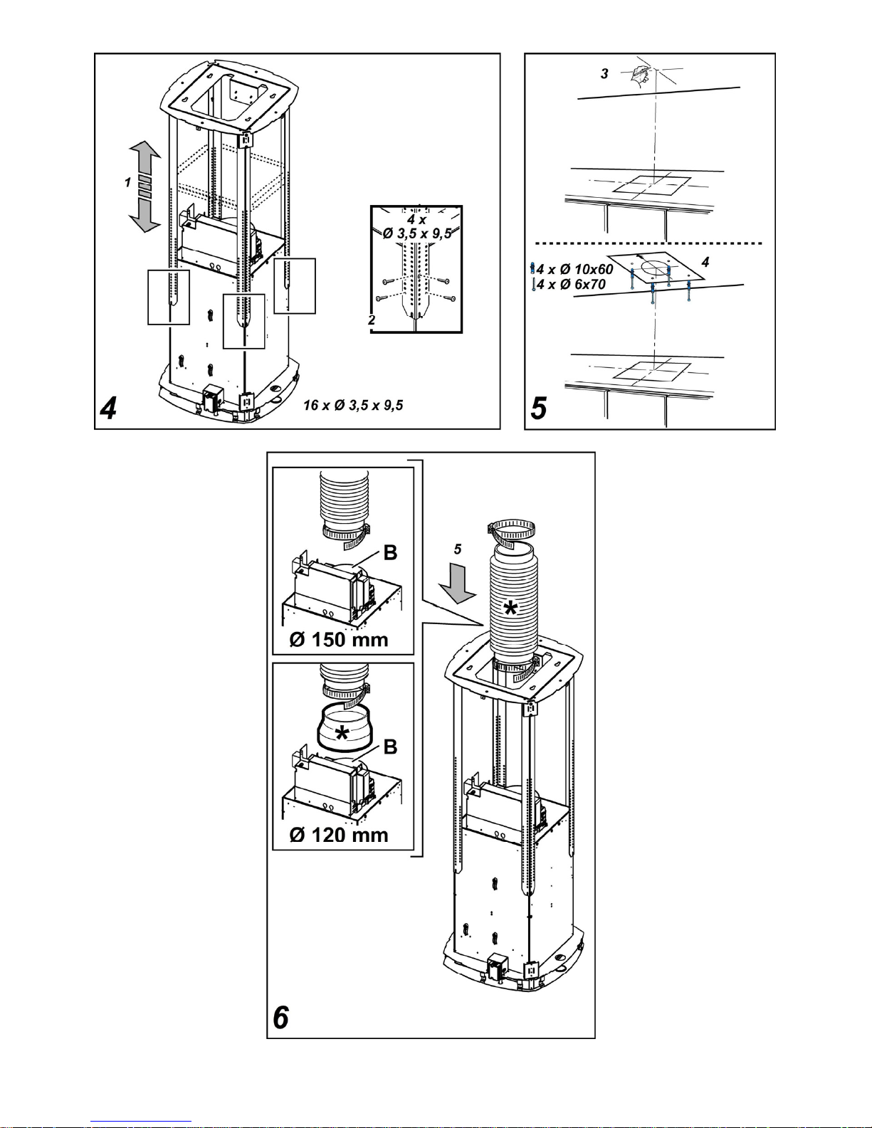
Fig. 4
1. Adjust extension of the hood support structure, as the
final height of the hood depends on this.
Note: In some cases the upper section of the lattice is
fixed to the lower section with one or more screws,
eventually check and remove them temporarily to allow
the adjustment of the support structure.
2. Fix the two sections of the structure with a total of 16
screws (four per corner).
Note: If supplied, temporarily remove the screws fixing
the reinforcement bracket to the perforated frame (keep
these screws in a safe place) and position it over the
motor assembly.
The bracket should be fixed in place again only after the
perforated frame has been fitted to the ceiling.
Fig. 5
3. Apply the drilling template to the ceiling so that it is
vertically in line with the hob (the centre of the template
should be aligned with the centre of the hob and the
sides should run parallel to the sides of the hob; the side
of the template displaying the text FRONT (or the arrows)
should correspond to the connection box side). Make the
electrical connection.
4. Make holes as indicated (4 holes for 4 wall dowels), Screw
in 4 screws into the holes indicated in the drawing leaving
a space between the head of the screw and the ceiling of
about 1 cm.
Fig. 6
5. Fit an exhaust pipe inside the truss and connect it to the
motor compartment connection ring (exhaust pipe and
fixing brackets are not supplied).
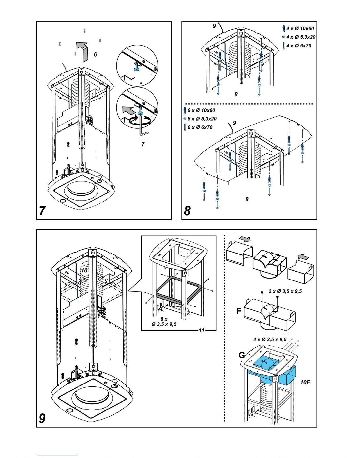
Fig. 7
6. Hook the frame onto the 4 screws (see step 4).
7. Tighten the 4 screws.
Fig. 8
8. Drill around the holes (4 or 6 holes) on the flange, fit the
rawl plugs into the wall and fix the screws and washers in
place.
9. Carry out the electrical connection to the mains power
supply, only turn on the power supply upon completion of
assembly.
Fig. 9
10. For extractor versions, connect the other end of the
exhaust pipe to the flue.
For filter versions (10F), fit deflector F to the truss and
secure it to the bracket supplied using 4 screws, then
connect the exhaust pipe to the connection ring located on
the deflector.
11. Fix the reinforcement bracket (see step 2) to the
perforated frame in a position which is as near to the
middle as possible.
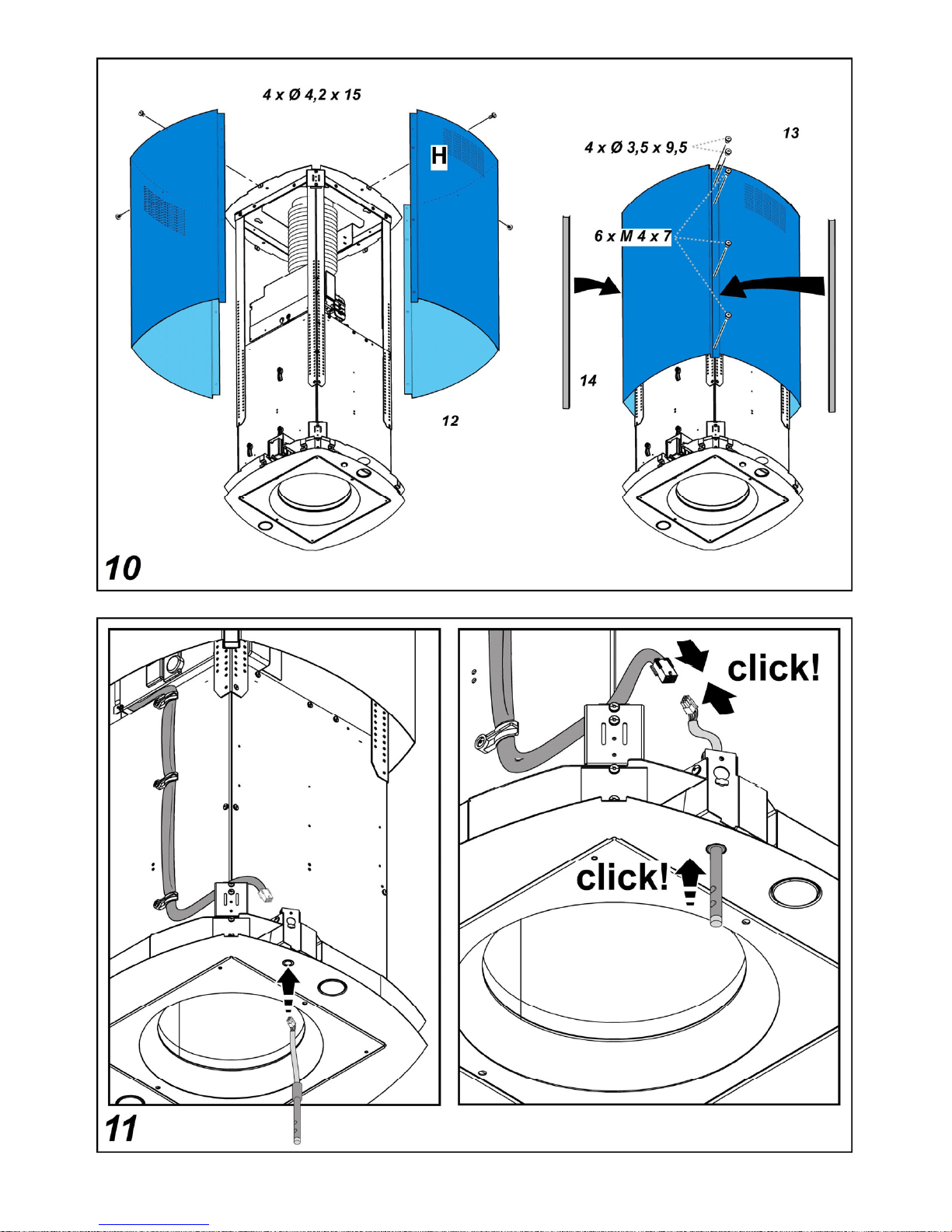
Fig. 10
12. Join the two upper sections of the duct covering the
perforated frame.
Fix each individual section in place using 2 screws (1 per
side) near the ceiling.
13. Fix the upper duct to the perforated frame using 10
screws (5 per side).
14. Apply 2 casings (supplied) to cover the fixing points on
the upper duct sections (CAUTION: THE UPPER DUCT
CASINGS ARE EASY TO RECOGNISE BECAUSE
THEY ARE WIDER, DEEPER AND ARE FITTED BY
PRESSING THEM INTO PLACE).
Fig. 11
15. Fit the control shaft in the correct position by
pushing it upwards.
16. Connect the electricity.
Fig. 12
17. First insert the lower section of the duct, on which the
threaded inserts can be found.
Fix it to the frame, tightening the first and fourth screws
on both sides (counting from the bottom).
18. Join the second lower section by tightening the second
and third screws on each side (counting from the
bottom).
Fix the 2 sections in place using 4 screws (2 per side).
Fig. 13
19. Apply 2 casings (supplied) to cover the fixing points on
the lower duct sections (CAUTION: THE LOWER DUCT
CASINGS ARE EASY TO RECOGNISE BECAUSE
THEY ARE NARROWER AND LESS DEEP).
Turn the mains power on again at the central electrical panel
and check for correct hood operation.
Page 9

18
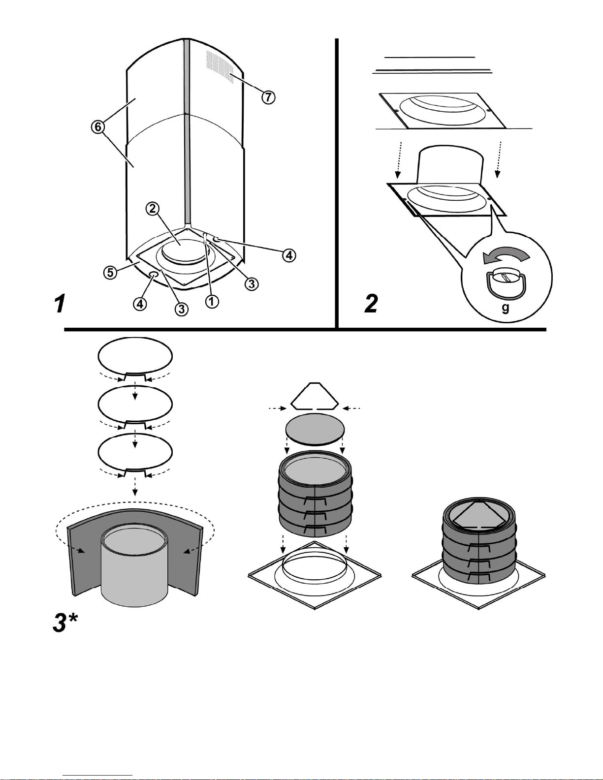
Description of the hood
Fig. 1
1. Control panel
2. Grease filter
3. Grease filter release handle
4. Halogen lamp
5. Vapour catcher
6. Telescopic chimney
7. Air outlet (used for filter version only)
Operation
Use the high suction speed in cases of concentrated kitchen
vapours. It is recommended that the cooker hood suction is
switched on for 5 minutes prior to cooking and to leave in
operation during cooking and for another 15 minutes
approximately after terminating cooking.
The hood is equipped with a “TOUCH” device to control the
lights and speed.
For the correct use please carefully read the intructions below.
The cooker hood can be controlled through a remote control
available as accessory kit (see the paragraph relating to the
functioning of the remote control).
Automatic start-up function
The hood is equipped with a temperature sensor which
activates the motor to the first suction speed (power) in the
event that the temperature in the surrounding area is higher
than 70°C.
The user may switch off or modify the suction speed (power)
(see paragraph “suction speed (power) control”).
Suction speed (power) control
The suction speed (power) is cyclical depending on the speed
sequence “stand-by – 1-2-3-4- Stand by -1-2-...” therefore
every time the T1 button is pressed on the control panel, the
suction speed (power) is increased by one level, in order to
switch off (stand-by) if the button is pressed again when the
hood is in suction speed (power) 4.
The hood may be switched off (stand-by) while the hood is set
on any speed by holding down the T1 button on the control
panel for a bit longer (more than 3 seconds).
The hood's suction speed (power) may be determined as the
control panel is equipped with a LED light that changes colors
as follows, depending on the suction speed (power):
Hood in stand-by: LED LIGHT SWITCHED OFF
1st suction speed (power) -GREEN LED LIGHT
2nd suction speed (power) – ORANGE LED LIGHT (amber)
3rd suction speed (power) - RED LED LIGHT
4th suction speed (power) - RED LED LIGHT (FLASHING)
Note: The 4th suction speed (power) stays on for 5 minutes,
after which the suction motor will position itself on the 2nd
speed.
If pressed again, the suction motor will switch off (stand-by).
Grease filters need cleaning: FLASHING GREEN LED light
(read instructions found under “Reset and configuration for
filter saturation signal”)
Coal filters must be cleaned or replaced: FLASHING
ORANGE (amber) LED light (read instructions found under
“Reset and configuration for filter saturation signal”)
Note: The reset procedure may be activated by both the
control panel and the remote control.
Center light check
The center light may be switched on and off by pressing the
T2 button on the control panel.
Side light check (when scheduled)
The side lights may be switched on and off by pressing AND
HOLDING DOWN the T2 button on the control panel.
HOLDING DOWN the button, besides permitting to switch the
hood on and off, it also regulates the light intensity given from
the lights.
Note: The switching on and off functions (and regulating
function) alternate.
The regulation of the light intensity is not available for hoods
with neon lights.
Reset and configuration for filter saturation signal
Switch on hood to any speed (see above paragraph “Suction
speed (power) selection”)
Reset grease filter saturation signal (FLASHING GREEN
LIGHT on control panel)
First proceed with filter maintenance as described in
corresponding paragraph.
Press and hold down (for more than 3 seconds) the T1 button
on the control panel, the LED light will stop flashing indicating
that the signal reset has been carried out, the hood will switch
off.
Reset coal filter saturation signal (FLASHING ORANGE
(amber) LED light)
First proceed with filter maintenance as described in
corresponding paragraph.
Press and hold down (for more than 3 seconds) the T1 button
on the control panel, the LED light will stop flashing indicating
that the signal reset has been carried out, the hood will switch
off.
Page 10

19
Coal filter saturation signal disactivaction (for particular
applications)
Switch off hood (see above paragraph “suction speed (power)
selection”).
Press and hold down (for more than 5 seconds) the T1 button
on the control panel, the LED light will start flashing GREEN
indicating that the coal filter saturation signal has been
disactivated.
In order to reactivate the coal filter saturation signal, repeat
operation, the LED light will flash ORANGE (amber)
Page 11

20
Remote control
Warning! Some functions of this remote control may only be activated with certain hood models.
Remote control affiliation:
Keep T2 +T5 pressed within the first minute the hood is powered.
Once pairing is complete it is displayed on the hood.
Description of the remote control functions
T1. OFF key
T2. ON/OFF key and dim light intensity adjustment
T3. Suction speed (power) control key:
T4. Hob light ON/OFF key
T5. Delayed hood ON/OFF key
T6. Sensor ON/OFF key.
T7. Filter saturation warning reset key.
L3. Remote control operation LED
Note: touch the keys lightly to select the available functions.
T1. OFF key
Press to switch the hood off
T2. ON/OFF key and dim light intensity adjustment
Press briefly to switch the dim light on or off
Press longer to adjust intensity.
Note: The dim light is only available on some models.
T3. Suction speed (power) control key
Touch the key starting from any position, turning it clockwise or
anticlockwise to increase or decrease suction speed.
The key is divided into several sectors. You can select the
desired speed directly in the corresponding sector as follows:
T3a: Speed 1 (low suction)
T3b: Speed 2 (medium suction)
T3c: Speed 3 (high suction)
T3d: Speed 4 (intensive suction)
T4. Hob light ON/OFF key
Press to switch the hob light on or off.
T5. Delayed hood ON/OFF key.
Press to program the delayed switch-off of the hood based on
the suction speed (power) active at that moment:
Speed 1 (low suction): 20 minutes
Speed 2 (medium suction): 15 minutes
Speed 3 (high suction): 10 minutes
T6. Sensor ON/OFF key
Keep it pressed to activate/deactivate the mode with sensor
which manages fume extraction in automatic mode.
Note: The sensor is only available in some models.
T7. Filter saturation warning reset key.
With the hood off, press T7, the LED L1 quits signalling the
saturation warning.
Page 12

21
Maintenance of the remote control
Cleaning the remote control:
Clean the remote control with a damp cloth and a neutral
solution of detergent without abrasive substances.
Changing the battery:
• Open the battery casing.
• Replace the flat batteries with 3 new 1.5 V type AAA
batteries.
Respect the polarity indicated in the battery casing when
inserting the new battery!
• Close the battery casing up again.
Disposal of the batteries
Ultimate disposal of the batteries should be handled according
to all national laws and regulations. Do not place used
batteries in your regular waste.
Ultimate disposal of the batteries must be done safely.
Contact your local waste management officials for other
information regarding the environmentally sound collection,
recycling, and disposal of the batteries.
Maintenance
ATTENTION! Before performing any maintenance operation,
isolate the hood from the electrical supply by switching off at
the connector and removing the connector fuse.
Or if the appliance has been connected through a plug and
socket, then the plug must be removed from the socket.
Cleaning
The cooker hood should be cleaned regularly (at least with the
same frequency with which you carry out maintenance of the
fat filters) internally and externally. Clean using the cloth
dampened with neutral liquid detergent. Do not use abrasive
products. DO NOT USE ALCOHOL!
WARNING: Failure to carry out the basic cleaning
recommendations of the cooker hood and replacement of the
filters may cause fire risks.
Therefore, we recommend observing these instructions.
The manufacturer declines all responsibility for any damage to
the motor or any fire damage linked to inappropriate
maintenance or failure to observe the above safety
recommendations.
Grease filter
Fig. 2
This must be cleaned once a month (or when the filter
saturation indication system – if envisaged on the model in
possession – indicates this necessity) using non aggressive
detergents, either by hand or in the dishwasher, which must
be set to a low temperature and a short cycle.
When washed in a dishwasher, the grease filter may discolour
slightly, but this does not affect its filtering capacity.
Remove the filter holder frame by turning the knobs (g) 90°
that affix the chimney to the cooker hood.
Charcoal filter (filter version only)
Fig. 3
It absorbs unpleasant odours caused by cooking.
The charcoal filter can be washed once every two months (or
when the filter saturation indication system – if envisaged on
the model in possession – indicates this necessity) using hot
water and a suitable detergent, or in a dishwasher at 65°C (if
the dishwasher is used, select the full cycle function and leave
dishes out).
Eliminate excess water without damaging the filter, then put it
in the oven for 10 minutes at 100° C to dry completely.
Replace the mattress every 3 years and when the cloth is
damaged.
Assembly
Place the mat around the grease filter and fix it in place using
the devices provided.
Position the upper cap and fix it in place using the fixing pin.
To disassemble, perform the steps in the reverse order.
Replacing lamps
The hood is equipped with a lighting system based on LED
technology.
The LEDs guarantee an optimum lighting, a duration up to 10
times as long as the traditional lamps and allow to save 90%
electrical energy.
For replacement, contact the technical service.
 Loading...