

Operating Manual
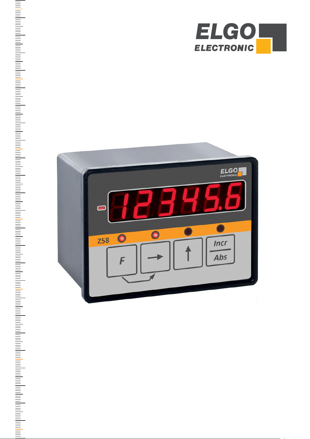
SERIES Z58-600
Universal Position Indicator for incremental and absolute Measuring Systems
Indicator for evaluation of incremental or absolute measuring systems
Proven standard functions, e. g. multiplication factor, reference value,
tool-offset, four-edge evaluation and inch/mm switching
6 digit LED display (14 mm high) with brightness control
3 external +24 V control inputs (reset, reference, tool-offset)
Switching function via two normally open relay outputs
Optional analog output 0 ... 10 V or 0 (4) ... 20 mA
Power supply 24 VDC (optionally 115 or 230 VAC)
Serial RS232 interface
799000082 / Rev. 0 / 2018-11-08
Translation of the original operating manual

- 2 -
Publisher
ELGO Electronic GmbH & Co. KG
Carl-Benz-Str. 1
D-78239 Rielasingen-Worblingen
Technical Support
+49 (0) 7731 9339 – 0
+49 (0) 7731 2 13 11
info@elgo.de
Document- No.
799000082
Document- Name
Z58-600-MA-E_45-18
Document- Revision
Rev. 0
Issue Date
2018-11-08
Copyright
© 2018, ELGO Electronic GmbH & Co. KG

Contents
- 3 -
1 Contents
1 Contents ............................................................................................. 3
2 List of Figures ..................................................................................... 4
3 List of Tables ...................................................................................... 4
4 General, Safety, Transport and Storage ........................................... 5
4.1 Information Operating Manual ............................................................................. 5
4.2 Explanation of Symbols ........................................................................................ 5
4.3 Statement of Warranties ....................................................................................... 6
4.1 Demounting and Disposal .................................................................................... 6
4.2 General Causes of Risk ........................................................................................ 6
4.3 Personal Protective Equipment ............................................................................... 6
4.4 Conventional Use ............................................................................................... 7
4.5 Safety Instructions for Transport, Unpacking and Loading .......................................... 7
4.6 Handling of Packaging Material ............................................................................ 7
4.7 Inspection of Transport ........................................................................................ 7
4.8 Storage ............................................................................................................. 7
5 Product Features ................................................................................ 8
5.1 Compatible Measuring Systems ............................................................................. 8
5.2 Digital Inputs ...................................................................................................... 8
6 Technical Data ................................................................................... 9
6.1 Identification ...................................................................................................... 9
6.2 Dimensions Panel Housing (standard) .................................................................... 9
6.3 Dimensions Built-on Housing (Option AG) ............................................................ 10
6.4 Technical Data Z58-600 .................................................................................... 11
7 Pin Assignments............................................................................... 12
7.1 Connection of Z58-600 (Standard 24 VDC) .......................................................... 12
7.2 Connection of Z58-654 (VAC Versions) ................................................................ 13
8 Installation and First Start-Up ......................................................... 14
8.1 Operating Area ................................................................................................ 14
8.2 Installation of the indicator ................................................................................. 15
9 Design and Functions ...................................................................... 16
9.1 Key Assignment and LED Overview ...................................................................... 16
9.2 Key Functions ................................................................................................... 16
9.3 Parameter Level ................................................................................................ 17
9.4 Parameter List................................................................................................... 18
9.5 Load Default Parameters .................................................................................... 18
9.6 Multiplication Factor .......................................................................................... 19

Contents
- 4 -
10 Normal Mode: Keys & external Inputs ............................................ 19
10.1 Reset............................................................................................................... 19
10.2 Absolute/Incremental Measurement ..................................................................... 19
10.3 Saw Blade Thickness ......................................................................................... 19
10.4 Switchable Tool-Offset ....................................................................................... 19
10.5 Set to Reference Value ....................................................................................... 19
11 Calibration of Absolute Measuring Systems.................................... 20
11.1 Guided FMAX Absolute Linear Encoder ................................................................ 20
11.2 Unguided EMAX Absolute Linear Encoder ............................................................. 20
12 Serial Interface ................................................................................ 21
12.1 Key Data ......................................................................................................... 21
12.2 Commands ...................................................................................................... 21
13 Disturbances, Maintenance, Cleaning ............................................. 22
13.1 Fault Clearance ................................................................................................ 22
13.2 Possible Errors and their Clearance ...................................................................... 22
13.3 Re-start after Fault Clearance .............................................................................. 22
13.4 Maintenance .................................................................................................... 23
13.5 Cleaning ......................................................................................................... 23
14 Type Designation ............................................................................. 24
14.1 Accessories ...................................................................................................... 24
15 Index ................................................................................................ 27
2 List of Figures
Figure 1: Panel housing (standard) ............................................................................................................. 8
Figure 2: Built-on housing (option) ............................................................................................................. 8
Figure 3: Dimensions panel housing (standard) ........................................................................................... 9
Figure 4: Dimensions built-on housing (Option AG) .................................................................................. 10
Figure 5: Installation into panel ................................................................................................................ 15
Figure 6: Housing underside with insert nuts.............................................................................................. 15
Figure 7: Key assignment and LED overview .............................................................................................. 16
3 List of Tables
Table 1: Compatible Measuring Systems .................................................................................................... 8
Table 3: Pin Assignment of Z58-600 ........................................................................................................ 12
Table 4: Pin Assignment of Z58-654 ........................................................................................................ 13
Table 2: Parameter list ............................................................................................................................ 18
Table 5: General interference clearance ................................................................................................... 22
General, Safety, Transport and Storage
- 5 -
DANGER!
This symbol in connection with the signal word “Danger” indicates an immediate danger for the life and health of
persons. Failure to heed these instructions can result in serious damage to health and even fatal injury.
WARNING!
This symbol in connection with the word „Warning” means a possibly impending danger for the life and health of
persons. Failure to heed these instructions can result in serious damage to health and even fatal injury.
CAUTION!
This symbol in connection with the signal word “Caution” indicates a possibly dangerous situation. Failure to heed
these instructions can lead to minor injuries or damage of property.
DANGER!
This symbol in connection with the signal word “Danger” indicates an immediate danger for the life and health of
persons due to voltage.
Failure to heed these instructions can result in serious damage to health and even fatal injury. The operations may
only be carried out by a professional electrician.
NOTE!
…points out useful tips and recommendations as well as information for an efficient and trouble-free operation.
4 General, Safety, Transport and Storage
4.1 Information Operating Manual
This manual contains important information regarding the handling of the device. For your own safety and operational safety, please observe all safety warnings and instructions. Precondition for safe operation is the compliance with the specified safety and handling instructions. Moreover, the existing local accident prevention regulations and the general safety rules at the site of operation have to be observed.
Please read the operating manual carefully before starting to work with the device! It is part of the product and should be kept close to the
device and accessible for the staff at any time. The illustrations in the manual are for better demonstration of the facts. They are not necessarily to scale and can slightly differ from the actual design.
4.2 Explanation of Symbols
Special notes in this manual are characterized by symbols. The notes are introduced by signal words which express the magnitude of danger.
Please follow this advice and act carefully in order to avoid accidents, damage, and injuries.
Warning notes:
Special safety instructions:
Tips and recommendations:
Reference marks:
Marks a reference to another chapter of this manual.
Marks a reference to another chapter of another document.
General, Safety, Transport and Storage
- 6 -
CAUTION!
Wrong disposal causes environmental damages!
Electronic scrap, electronic components, lubricants and other auxiliary materials are subject to special refuse and can
only be disposed by authorized specialists!
CAUTION!
Please read the operating manual carefully, before using the device! Observe the installation instructions!
Only start up the device if you have understood the operating manual.
The operating company is obliged to take appropriate safety measure.
The initial operation may only be performed by qualified and trained staff.
Selection and installation of the devices as well as their embedding into the controlling system require qualified
knowledge of the applicable laws and normative requirements on the part of the machine manufacturer.
PROTECTIVE CLOTHING
… is close-fitting working clothing with light tear strength, tight sleeves and without distant parts. It serves preliminarily for protection against being gripped by flexible machine parts.
Do not wear rings, necklaces or other jewelry.
PROTECTIVE GLOVES
…for protecting the hands against abrasion, wear and other injury of the skin.
PROTECTIVE HELMET
…for protection against injuries of the head.
4.3 Statement of Warranties
The producer guarantees the functional capability of the process engineering and the selected parameters.
4.1 Demounting and Disposal
Unless acceptance and disposal of returned goods are agreed upon, demount the device considering the safety instructions of this manual
and dispose it with respect to the environment.
Before demounting:
Disconnect the power supply and secure against re-start. Then disconnect the supply lines physically and discharge remaining energy. Remove operational supplies and other material.
Disposal:
Recycle the decomposed elements: Metal components in scrap metal, Electronic components in electronic scrap, Recycle plastic components, dispose the remaining components according to their material consistence.
Local authorities and waste management facilities provide information about environmentally sound disposal.
Safety
4.2 General Causes of Risk
This chapter gives an overview of all important safety aspects to guarantee an optimal protection of employees and a safe and trouble-free
operation. Non-observance of the instructions mentioned in this operating manual can result in hazardous situations.
4.3 Personal Protective Equipment
Employees have to wear protective clothing during the installation of the device to minimize danger of health.
Therefore:
Change into protective clothing before performing the works and wear them throughout the process.
Additionally observe the labels regarding protective clothing in the operating area.
Protective clothing:
General, Safety, Transport and Storage
- 7 -
CAUTION!
Danger through non-conventional use!
Non-intended use and non-observance of this operating manual can lead to dangerous situations.
Therefore:
Only use the device as described
Strictly follow the instructions of this manual
Avoid in particular:
Remodeling, refitting or changing of the construction or single components with the intention to alter the
functionality or scope of the device.
CAUTION!
Transport the package (box, palette etc.) professionally.
Do not throw, hit or fold it.
NOTE!
Claim any damage immediately after recognizing it.
The claims for damage must be filed in the lawful reclaim periods.
4.4 Conventional Use
The ELGO-device is only conceived for the conventional use described in this manual.
The ELGO device type Z58-600 only serves to visualize positions, lengths and distances.
Claims resulting from damages due to non-conventional use are not possible.
Only the operator is liable for damages caused by non-conventional use.
4.5 Safety Instructions for Transport, Unpacking and Loading
4.6 Handling of Packaging Material
Notes for proper disposal: 4.1
4.7 Inspection of Transport
Check the delivery immediately after the receipt for completeness and transport damage.
In case of externally recognizable transport damages:
Do not accept the delivery or only accept under reserve.
Note the extent of damages on the transportation documents or delivery note.
File complaint immediately.
4.8 Storage
Store the device only under the following conditions:
Do not store outside
Keep dry and dust-free
Do not expose to aggressive media
Protect from direct sun light
Avoid mechanical shocks
Storage temperature (0) needs to be observed
Relative humidity (0) must not be exceeded
Inspect packages regularly if stored for an extensive period of time (>3 months)

Product Features
- 8 -
Measuring principle
Compatible Measuring Systems
Incremental
Conventional HTL- and TTL rotary encoders as well as the unguided ELGO linear
encoders LMIX, EMIX, DMIX, GMIX, RMIX or guided FMIX and PMIX systems
Absolute
ELGO EMAX (unguided) and FMAX (guided). FMAX calibration see chapter 11
Figure 1: Panel housing (standard)
Figure 2: Built-on housing (option)
5 Product Features
The universal ELGO position indicator Z58-600 is suitable for detecting
lengths and positions. The device has 2 programmable pre-selections in
order to control 2 internal normally open relays.
Both conventional incremental encoders and incremental or absolute
ELGO measuring systems can be connected as input signals. It is therefore a universal device which can visualize the information of numerous
ELGO standard measuring systems.
With the Z58-600, ELGO is able to offer a complete solution concerning
signal detection and visualization.
The predecessor type Z54 can be replaced by Z58 (except for a few
special devices). Please consider the pin assignment during Z54 replacement, because with Z58 additional plugs for news encoder types
are available.
Essential Features:
Power supply:
- 24 VDC (standard)
- 115/230 VAC with external ELGO power pack NG24.0 possible
- 115 VAC-supply alternatively available when order type Z58-654-115-X (restrictions 7.2)
- 230 VAC-supply alternatively available when order type Z58-654-230-X (restrictions 7.2)
Standardly with panel mounting housing (cut-out = 93 x 67 mm)
Optionally with built-on housing for surface mounting available
Installation depth = 73 mm (110 mm inclusive D-SUB connector)
RS232 interface for transmission of the actual value
All connections are pluggable
5.1 Compatible Measuring Systems
Table 1: Compatible Measuring Systems
5.2 Digital Inputs
The unit has 3 external inputs for triggering the setting functions (reset, reference and tool-offset).
These inputs are available at the 6-pin Phoenix connector S2 and have the following properties:
Characteristic: PNP, active high
Switching voltage: +24 VDC
Input current: max. 10 mA
Technical Data
- 9 -
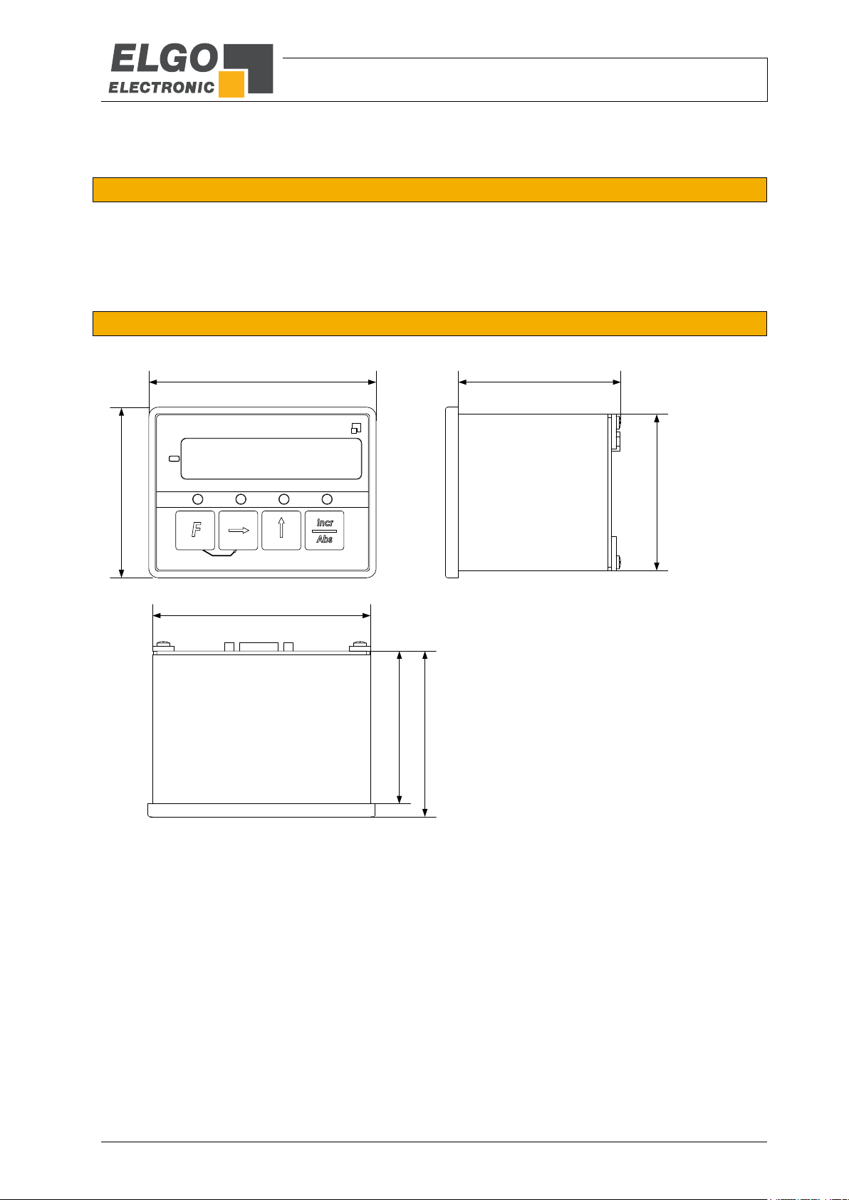
96
72
66
92
64,5
70
69
ELGO
Electronic
Z58
6 Technical Data
6.1 Identification
The type label serves for the identification of the unit. It is located on the housing of the device and indicates the
exact type designation (= order reference 14) with the corresponding part number. Furthermore, the type
label contains a unique, traceable device number. When corresponding with ELGO please always indicate this
data.
6.2 Dimensions Panel Housing (standard)
Figure 3: Dimensions panel housing (standard)

Technical Data
- 10 -
60
30
Screw max. 15 mm
95
90
71.30
102.60
+ 0.2
+ 0.2
± 0.2
Side view
Front
Front
Rear
Insert nut M6
6.3 Dimensions Built-on Housing (Option AG)
Figure 4: Dimensions built-on housing (Option AG)

Technical Data
- 11 -
Z58-600 (standard version)
Mechanical Data
Housing
panel housing (standard) or built-on housing (option A)
Housing material
aluminium, black
Housing dimensions (W x H)
panel housing (standard): W x H x D = 96 x 72 x 70 mm
built-on housing (option A): W x H x D = 71.3 x 102.6 x 95 mm
Panel cut out (W x H)
W x H = 93 x 67 mm
Keyboard
foil with short stroke keys
Installation depth
78 mm (including screw terminals)
115 mm (including D-SUB connector)
Electrical Data
Display
6-digits LED (red, digit height: 14 mm)
Accuracy
± 1 Digit
Power supply voltage
Standard: 24 VDC ± 20 %
Version Z58-654-115-X-A: 115 VAC
Version Z58-654-230-X-A: 230 VAC
Current consumption
70 mA (without measuring system)
Signal inputs
HTL / TTL / RS422 (depends on order)
Input channels (incremental)
A, B resp. A, A', B, B', Z, Z'
Channels for absolute encoders
RX, RX‘, TX, TX‘
Input frequency
max. 100 KHz (optionally 500 KHz)
External inputs
3 digital inputs (set functions)
characteristics: PNP, active high
switching voltage: +24 VDC
input current: max. 10 mA
Relay outputs
2 potential-free shutters (24 VDC / max. 1 A)
Analog outputs (option)
12 Bit, 0... 10 VDC (max.= 5mA) or 0 (4)... 20mA (R
max
= 200 Ω)
Interfaces
RS232 (transmission of actual value)
Connections
pluggable screw terminals and 9 pin (female) D-SUB connectors
Data memory
EEPROM
Optional accessories
external power pack NG24.0 for 115/230 VAC supply
Environmental conditions
Operating temperature
0 … +50 °C
Storage temperature
-20 … +80 °C
Humidity
max. 80 %, non-condensing
Protection class (front)
IP43 (installed state)
Protection class (rear)
IP40
6.4 Technical Data Z58-600

Pin Assignments
- 12 -
Rear (example full assembly)1
Pin
ST1 - (standard encoders)
1
0 V / GND (encoder supply)
2
+5 V or +24 V out (encoder supply)
3
Channel A
4
Channel B
5
Screen / shield
6
Channel A‘ (only with 5 V encoders)
7
Channel B‘ (only with 5 V encoders)
8
Channel Z‘ (only with 5 V encoders)
9
Channel Z
Pin
ST2 - (power supply and external inputs)
Pin
ST3 - (FMAX / EMAX, relays, analog outputs)
1
Screen / shield
1
Screen / shield
2
0 V / GND
2
0 V / GND (encoder supply)
3
+24 VDC (power supply voltage)
3
+5 V / +24 V out (encoder supply)
4
Tool-offset (active high)
4
RS422_RX’
5
Reference (active high)
5
RS422_RX
6
Reset (active high)
6
RS422_TX’
Pin
ST4 - (differential encoders)
7
RS422_TX
1
0 V / GND
8
n. c.
2
+5 V / +24 V out (encoder supply)
9
Analog output (0 ... 10 VDC)
3
Channel A
10
Analog output (0/4 ... 20 mA)
4
Channel B
11
Relay_1_A
5
0 V / GND (encoder supply)
12
Relay_1_B
6
Channel A‘
13
Relay_2_A
7
Channel B‘
14
Relay_2_B
8
Channel Z
Pin
ST5 - (RS232 interface)
9
Channel Z‘
2
TxD
Inverted signals are marked with '
3
RxD 5 0 V / GND
REMARK!
When using encoders with 24 V resp. 10 ... 30 V signals,
the inverted signals must not be connected.
1
ST5
ST4
ST3
ST1
ST2
1 2 3 4 5 6 7 8 9 10 1112 13 14
1 2 3 4 5 6 7 8 9
1 2 3 4 5 6
7 Pin Assignments
7.1 Connection of Z58-600 (Standard 24 VDC)
Table 2: Pin Assignment of Z58-600
Depending on version and selected options, only the relevant connectors are fitted resp. terminals are occupied

Pin Assignments
- 13 -
REMARK!
The 115/230 VAC versions are mainly offered to replace the predecessor type Z54 standard.
For technical reasons the above encoders and options cannot be realized here. However, if you
need any of the above encoders/options and do not have a 24 VDC power supply, please use
the Z58-600 standard device in combination with the external ELGO power pack NG24.0,
which is available as an accessorial component ( 14.1).
Rear
Pin
ST2 - (external inputs)
1
Screen / shield
2
0 V / GND
3
+24 VDC out (HIGH level)
4
Tool-offset (active high)
5
Reference (active high)
6
Reset (active high)
Pin
ST1 - (rotary encoder)
Pin
ST3 - (AC supply)*
1
0 V / GND (encoder supply)
1
L1 2 +24 V out (encoder supply)
2
N
3
Channel A
3
PE 4 Channel B
*) ST3 is not required for option AG (built-on housing).
A separate connector for AC supply is included.
5
Screen / shield
ST1
1 2 3 4 5
ST2
1 2 3 4 5 6
External power plug
only with option AG*
ST3*
1 2 3
7.2 Connection of Z58-654 (VAC Versions)
Additional description for connecting devices with 115 or 230 VAC power supply
ATTENTION!
The following functions, encoders and options ( 14) are not available with VAC-versions (654):
1. Unavailable Standard Functions:
For technical reasons, no relay outputs can be equipped.
2. Unavailable Measuring Systems:
1 = A/B/Z with 24 VDC encoder supply, HTL (PNP), 100 KHz
2 = A/A’ B/B’ Z/Z’ with 24 VDC encoder supply, TTL (PNP), 100 KHz
3 = A/A’ B/B’ Z/Z’ with 5 VDC encoder supply, TTL (PNP), 100 KHz
4 = compatible to ELGO FMAX absolute encoders
5 = compatible to ELGO EMAX absolute encoders
8 = A/A’ B/B’ Z/Z’ with 24 VDC encoder supply, TTL (PNP), 500 KHz
9 = A/A’ B/B’ Z/Z’ with 5 VDC encoder supply, TTL (PNP), 500 KHz
3. Unavailable Options:
F = analog output 0 ... 10 V
G = analog output 0 ... 20 mA
H = analog output 4 ... 20 mA
7.2.1 Pin Assignment of Z58-654
Table 3: Pin Assignment of Z58-654

Installation and First Start-Up
- 14 -
CAUTION
Please read the operating manual carefully before using the device! Strictly observe the Installation instructions!
In case of damage caused by failure to observe this operating manual, the warranty expires.
ELGO is not liable for any secondary damage and for damage to persons, property or assets.
The operator is obliged to take appropriate safety measures.
The first start-up may only be performed by qualified staff that has been trained and authorized by the operator.
WARNING!
Do not use the device in explosive or corrosive environments!
The device must not be installed close to sources of strong inductive or capacitive interference or strong electrostatic
fields!
CAUTION!
The electrical connections must be made by suitably qualified personnel in accordance with local regulations.
The device may be designed for switchboard mounting. During work on the switchboard, all components must be deenergized if there is a danger of touching the energized parts!
(protection against contacts)
Wiring works may only be performed in the de-energized state!
Thin cable strands have to be equipped with end sleeves!
Before switching on the device, connections and plug connectors have to be checked!
The device must be mounted in a way that it is protected against harmful environmental influences such as splashing
water, solvents, vibration, shock and severe pollution and the operating temperature must not be exceeded.
8 Installation and First Start-Up
8.1 Operating Area

Installation and First Start-Up
- 15 -
ATTENTION!
The length of the screws used must not exceed 15 mm! Otherwise
the electronics will be damaged and the device may be destroyed.
panel
grub scews
Phillips screw
panel from the
back side
mounting
bracket (2 x)
Z58 rear
panel
Screw max. 15 mm
Insert nut M6
8.2 Installation of the indicator
8.2.1 Panel Housing (standard)
The position indicator is intended for installation in a panel cut-out with the dimensions W x H = 93 x 67 mm.
For mounting a 1 slotted screwdriver and 1 Phillips screwdriver is required. Then proceed as follows:
1. 2. 3.
Figure 5: Installation into panel
1. First slide the position indicator into a suitable panel cut-out.
2. Then loosen the two Phillips screws of the diagonally mounted mounting brackets on the rear. Turn the two
mounting brackets so that the threaded holes point outwards and then tighten the Phillips screws.
3. Now insert the provided grub screws into the threaded holes of the mounting brackets and turn clockwise
until the device is firmly seated in the cut-out.
8.2.2 Built-on Housing (Option „A“)
In order to fasten the device by using two M6 screws, the built-on housing has two insert nuts on the underside
(see figure below). The hole distance is 60
±0,2
mm (see 6.3).
Figure 6: Housing underside with insert nuts

Design and Functions
- 16 -
9.2.1 Key Functions in Normal Mode:
+
Short keystroke set to reference value
Press for 3 seconds edit reference value (Parameter P09)
+
Press for 3 seconds enter parameter level
Short keystroke activate tool-offset
Repeated keystroke undo
+
Short keystroke absolute/relative measurement switchover
9.2.2 Key Functions in Parameter Level:
Short keystroke confirm & save parameter / step to next parameter
Short keystroke select decade
Short keystroke increase decade
Sign changeover (only relevant parameters)
+
Press for 3 seconds switch back to normal mode
(option)
lights up when relay active
(option)
lights up when relay active
F
Incr
Z58
Abs
Directional sign (lights up
when counter value is negative)
Status Relay 1
Status Relay 2
Set to reference value
Tool offset Absolute / Relative measurement
Tool offset
lights up when active
Incr/Abs
lights up when „Incr“ active
*) only in „Normal Mode“
**
F
F
Incr
Abs
Incr
Abs
Incr
Abs
F
F
Incr
Abs
9 Design and Functions
9.1 Key Assignment and LED Overview
Figure 7: Key assignment and LED overview
9.2 Key Functions

Design and Functions
- 17 -
9.3 Parameter Level
9.3.1 Enter Paramater Level
Press F + Incr/Abs for 3 seconds at the same time:
P 01 appears in the display („0“ is flashing) the parameter level is active
The corresponding key functions for programming are described in the previous section 9.2.2.
9.3.2 Parameter Description
All available parameters are described in detail here:
P00 = Reserved for test purposes
P01 = The counting direction can be reversed here (setting 0 or 1).
P02 = No function / reserved
P03 = Selection of the decimal place
P04 = Actual value memory can be activated/deactivated here.
P05 = Keypad lock/ keypad enable (the parameter level always remains active)
P06 = Select the edge evaluation (x 1, x 2 x or x 4)
P07 = Measuring system selection:
The connected measuring system must be selected here:
Setting 0 = Inkrementelle Messsystemsignale A/B/Z (z. B. EMIX/LMIX/PMIX/FMIX oder Drehgeber)
Setting 1 = Incremental encoder signals A/A’, B/B’, Z/Z’ (for differential encoder types)
Setting 2 = Absolute signals of ELGO - EMAX (via RS422 interface)
Setting 3 = Absolute signals of ELGO - FMAX (via RS422 interface)
P08 = Multiplication factor:
For details of the pulse scaling refer to section 9.6.
P09 = Reference value:
A reference value can be entered here which is taken over into the display when keys F + ►are pressed
or the external reference input is activated.
P10 = Tool-offset:
An offset dimension can be defined here. By pressing the ►or activating the external tool-offset input
the display will add this value to the actual value.
P11 = Saw blade thickness (Incr-Mode only):
In order to compensate the thickness of a saw blade of a saw machine, the value can be stored here.
P12 = Preset limit for relay 1 (min) activates when underrun
P13 = Preset limit for relay 2 (max) activates when overrun
P14 = Display brightness:
To adjust the brightness of the LED display digitally from 0 (darkest) to 9 (brightest).
P15 = No function / reserved
P16 = Default parameters:
Details about resetting the Z58 to the default parameters can be found in section 9.5.
P17 = Measurement unit mm or inch:
Defines whether the position display is to be operated in millimeters or inches.
P20 = Analog (minimum value):
Enter the value at which the analog output controls 0 V resp. 0 / 4 mA.
P21 = Analog (maximum value):
P22 … P98 are without function or reserved
P99 = Indicates the software version of the device (useful for service calls).
Note: A tabular overview of all parameters can be found in the parameter list 9.4.
Enter the value at which the analog output controls 10 V resp. 20 mA.

Design and Functions
- 18 -
Parameter
Function
Range
Default Setting
P 00
reserved for test purposes
- - - - - -
P 01
Counting direction (0 = up / 1 = down)
0, 1
0
P 02
no function / reserved
- - - - - -
P 03
Decimal place
0, 1, 2, 3
1
P 04
Actual value memory
(0 = enabled / 1 = disabled)
0, 1
0
P 05
Front keys (0 = enabled / 1 = disabled)
0, 1
0000
P 06
Edge evaluation (0 = x 1, 1 = x 2, 2 = x 4)
0, 1, 2
0
P 07
Measuring system selection:
(0 = A/B Encoder, 1 = RS422 Encoder,
2 = EMAX/FEMAX, 3 = FMAX,)
0, 1, 2, 3
0
P 08
Multiplication factor
00.0001 ... 99.9999
01.0000
P 09
Reference value
−99999.9 ... +99999.9
00000.0
P 10
Tool-offset
−99999.9 ... +99999.9
00000.0
P 11
Saw blade thickness
0 ... +99999.9
00000.0
P 12
Preset limit relay 1 (min)
−99999.9 ... +99999.9
00000.0
P 13
Preset limit relay 2 (max)
−99999.9 ... +99999.9
00000.0
P 14
Display brightness
0 ... 9
5
P 15
no function / reserved
- - - - - -
P 16
Load default parameters (0 = no / 1 = yes)
0, 1
0
P 17
Measurements unit (0 = mm / 1 = inch)
0, 1
0
P 18
no function / reserved
- - - - - -
P 19
no function / reserved
- - - - - -
P 20
Analog output (minimum value)
−99999.9 ... +99999.9
00000.0
P 21
Analog output (maximum value)
−99999.9 ... +99999.9
00000.0
P 22 ... 98
no function / reserved
- - - - - -
P99
Software-Version
XX.XX
9.4 Parameter List
Table 4: Parameter list
9.5 Load Default Parameters
Parameter P16 can be used to reset all parameters to their default settings. For this purpose set P16 to „1“,
press F + Incr/Abs for 3 s at the same time and switch the power of the Z58 indicator 1 x OFF and ON again.

Design and Functions
- 19 -
ATTENTION!
The static input must not remain closed, otherwise a "permanent reset"
is pending and the indicator is not able to count.
9.6 Multiplication Factor
The possible setting range of the multiplication factor for the pulse scaling is between 0.0001 and 9.9999. This
applies equally to the millimeter mode and the inch mode. The resolution decreases with factors > 1.
Calculating the multiplication factor:
Nominal (defined value)
Factor:
Actual (displayed value)
Example:
100.0
Factor: = 0.9950
100.5
10 Normal Mode: Keys & external Inputs
10.1 Reset
The display value can be reset by briefly connecting the external reset input ST2/Pin 6 (see 7) to HIGH resp.
+ 24 V. A push-button without latch is best suited for this purpose.
10.2 Absolute/Incremental Measurement
By pressing the Incr/Abs key in the normal mode, the measurement can be switched from the (total) absolute
to the (relative) incremental mode. In incremental mode, the display is set to "0" at the current position and the
device counter starts from this point.
By pressing the Incr/Abs key again, the device switches back to the absolute (total) measurement.
10.3 Saw Blade Thickness
This register is normally set to "0". If a value is deposited in parameter P11, this value is active as saw blade
thickness and will be compensated in the display.
Please note: The saw blade thickness is only active in the incremental measurement mode (see previous section).
10.4 Switchable Tool-Offset
By pressing ▲ in normal mode or alternatively activating the external input ST2/Pin 4, the indicator adds the
value stored in register P10 to the actual display value. The operation can be undone by pressing the ▲ key
again.
10.5 Set to Reference Value
By pressing F + ► at the same time in the normal mode or alternatively activating the external input ST2/Pin 5,
the value stored in register P09 is overtaken into the display.

Calibration of Absolute Measuring Systems
- 20 -
REMARK!
In case of replacing the FMAX, a new calibration procedure must be performed.
0.00
L 2
L 1
L 0
11 Calibration of Absolute Measuring Systems
11.1 Guided FMAX Absolute Linear Encoder
When using an FMAX ( 14 „Signal inputs = 4“), a one-time calibration of the measuring system is required.
The calibration is done as follows:
1. Press the keys ►+▲ in the normal mode for 3 seconds at the same time:
appears in the display
2. Move the FMAX sensor back and forth by approx. 2 cm and press the ► key:
appears in the display
3. Now move the FMAX sensor to the desired zero point and press the ► key:
appears in the display
4. When the button is released, the system is calibrated and the display shows
11.2 Unguided EMAX Absolute Linear Encoder
When using an EMAX ( 14 „Signal inputs= 5“), no calibration must be performed.

Serial Interface
- 21 -
low byte high byte
high nibble low nibble
12 Serial Interface
When connecting the serial interface, the current actual value of the Z58 unit can be transmitted to a PC or to a
higher-level system.
12.1 Key Data
Interface: RS232 (standard)
Baud rate: 9600 baud
Data format: 8 data bit, 1 stop bit, no parity
Communication: Z58 responds only to PC request
12.2 Commands
Read out the actual value:
Command: STX ´i´ ETX
Example: 02h 69h 03h
Response: e.g. B. 9712.3 (decimal) bzw. 0001 7B63 (hexadecimal)
STX <8 byte data> CRC ETX
02h 36h 33h 37h 42h 30h 31h 30h 30h A3h 03h
Remarks:
The data is transmitted in hexadecimal ASCII code, starting with the LOW byte.
In case of an invalid command, a "Q" is sent
The CRC is an addition of the 8 data bytes (a possible carry is omitted)

Disturbances, Maintenance, Cleaning
- 22 -
CAUTION!
The device, the connection line and the signal cable must not be installed next to sources of interference that emit
strong inductive or capacitive interference or strong electrostatic fields.
External perturbations can be avoided thorough suitable cable routing.
The screen of the signal output cable should only be connected to the following circuit on one side. The screens
should not be grounded on both sides. Signal cables always have to be routed separately from the load power line.
A safety distance of at least 0.5 m has to be kept from inductive and capacitive sources of interference such as contactors, relays, motors, switching power supplies, clocked controllers etc.!
If interferences occur in spite of all the items stated above being observed, please proceed as follows:
1. Installation of RC-circuits via contactor coils of AC-contactors (e.g. 0.1 µF / 100 Ω)
2. Installation of recovery diodes via DC-inductors
3. Installation of RC-circuits via the different motor phases (in the terminal box of the motor)
4. Do not connect protective earth and ground
5. Connect a mains filter ahead of the external power pack
Error No..
Meaning
Required Measure
190
EEPOM damaged
Send the device back for repair
WARNING! Danger of injury through non-conventional fault clearance!
Non-conventional fault clearance can lead to severe injuries and damage of property. Therefore:
Any work to clear the faults may only be performed by sufficiently qualified staff
Arrange enough space before starting the works
Make sure that the mounting area is clean and tidy. Loose components and tools are sources of accidents.
If components need to be replaced:
Pay attention to a correct installation of the spare parts.
Reinstall all the fixing elements properly
Before turning on the device, ensure that all covers and safety equipment is installed correctly and functions
properly
13 Disturbances, Maintenance, Cleaning
This chapter describes possible causes for disturbances and measures for their removal. In case of increased disturbances, please follow the
measures for fault clearance in chapter 13.1. In case of disturbances that cannot be eliminated by following the advice and the fault clearance measures given here, please contact the manufacturer (see second page).
13.1 Fault Clearance
13.2 Possible Errors and their Clearance
The following table shows possible interferences and their clearance.
Table 5: General interference clearance
13.3 Re-start after Fault Clearance
After the fault clearance:
1. Reset the emergency stop mechanism if necessary
2. Reset the error report at the super-ordinate system if necessary.
3. Ensure that there are no persons in the danger area.
4. Follow the instructions from chapter 7.

Disturbances, Maintenance, Cleaning
- 23 -
WARNING!
Danger through non-conventional maintenance!
Non-conventional maintenance can lead to severe injuries and damage of property.
Therefore:
Maintenance works may only be completed by staff that has been authorized and trained by the operator.
WARNING!
The device can only be cleaned with a damp cloth, do not use aggressive cleanser!
13.4 Maintenance
The device is maintenance-free.
13.5 Cleaning

Type Designation
- 24 -
NOTE
When ordering, please use the here described ordering code (Type Designation).
Options that are not required are filled in with „-„.
Order Designation
Description
NG24.0
External 24 VDC power pack (primary 115/230 VAC) for supply with AC voltage.
With two mounting holes as well as a snap-on device for top hat rail mounting.
Z58 024 XXXXX
Device Designation:
Z58 = Single Axis Position Indicator
Power Supply Voltage:
024 = 24 VDC
Measuring System:
1 = A/B/Z with 24 VDC encoder supp ly, HTL (PNP), 100 KHz
2 = A/A’ B/B’ Z/Z’ with 24 VDC encoder supply, TTL (PNP), 100 KHz
3 = A/A’ B/B’ Z/Z’ with 5 VDC encoder supply, TTL (PNP), 100 KHz
4 = compatible to ELGO FMAX absolute encoders
5 = compatible to ELGO EMAX ab solute encoders
7 = A/B/Z with 5 VDC encoder supp ly, TTL (PNP), 100 KHz
8 = A/A’ B/B’ Z/Z’ with 24 VDC encoder supply, TTL (PNP), 500 KHz
9 = A/A’ B/B’ Z/Z’ with 5 VDC encoder supply, TTL (PNP), 500 KHz
10 = A/B/Z with 24 VDC encoder supply, HTL (PNP), 500 KHz
Version:
00 = standard version
01 = 1. customer specified version
02 = 2. customer specified version (etc.)
-
Options:
A = built-on housing
F = analog output 0 ... 10 V
G = analog output 0 ... 20 mA
H = analog output 4 ... 20 mA
D = 9-pin (male) D-SUB connector for LMIX/EMIX
X--- 600
14 Type Designation
14.1 Accessories
Table 1: Accessories

- 25 -
Notes:

- 26 -
Notes:

Index
- 27 -
15 Index
Accessories ..................................................... 24
Accident prevention regulations........................... 5
Calibration of Absolute Measuring Systems ........ 20
Causes of risk .................................................... 6
Cleaning ................................................... 22, 23
Compatible Measuring Systems ........................... 8
Connection of Z58-600 / VDC ......................... 12
Connection of Z58-654 / VAC ......................... 13
Conventional use ............................................... 7
Demounting ...................................................... 6
Design and Functions ....................................... 16
Device number .................................................. 9
Digital Inputs ..................................................... 8
Dimensions Built-on Housing (Option AG) ......... 10
Dimensions Panel Housing (standard) .................. 9
Disposal............................................................ 6
Disturbances ................................................... 22
Explanation of symbols ....................................... 5
Fault clearance ................................................ 22
First start-up .................................................... 14
Identification ..................................................... 9
Installation ...................................................... 14
Installation of the indicator ............................... 15
Key assignment and LED overview ..................... 16
Key Functions in Normal Mode ......................... 16
Key Functions in Parameter Level ....................... 16
Load Default Parameters .................................. 18
Maintenance ............................................. 22, 23
Multiplication Factor ........................................ 19
Normal Mode - Keys & external Inputs .............. 19
Operating area ............................................... 14
Operational safety ............................................. 5
Order reference ................................................ 9
Packaging material ............................................ 7
Parameter Description ..................................... 17
Parameter Level............................................... 17
Parameter List ................................................. 18
Pin Assignments .............................................. 12
Product Features ............................................... 8
Protection against contact ................................ 14
Protective equipment ......................................... 6
Safety ........................................................... 5, 6
Safety instructions .............................................. 5
Safety rules ....................................................... 5
Serial Interface ................................................ 21
Start-up .......................................................... 14
Storage ............................................................ 7
Technical Z58-600 .......................................... 11
Transport .......................................................... 7
Transport damage ............................................. 7
Type Designation ............................................ 24

- 28 -
Document- No.:
799000082 / Rev. 0
Document- Name:
Z58-600-MA-E_45-18
Subject to change - © 2018
ELGO Electronic GmbH & Co. KG
EL G O Electron i c GmbH & Co. KG
Me as uri ng | Po sit ion ing | C ont rol
Carl - Benz - Str. 1, D -782 39 R iela sing en
Fon:+49 (0) 7731 9339-0, Fax:+49 (0) 7731 28803
Internet: www.elgo.de, Mail: i nfo@elgo.de
 Loading...