


Operating Manual
SERIES Z25-000
Single Axis Position Indicator (24 VDC)
Position indicator with signal input for 1 axis
Suitable for conventional rotary and linear encoder and
for incremental and absolute ELGO measuring systems
Adjustable reference value, tool offset and saw blade width
LCD display with 7 digits, sign and measurement unit
2 programmable digital control inputs
Power down memory
799000592 / Rev. 4 / 2017-05-08
Translation of the original operating manual

- 2 -
Publisher
ELGO Electronic GmbH & Co. KG
Carl-Benz-Str. 1
D-78239 Rielasingen-Worblingen
Technical Support
+49 (0) 7731 9339 – 0
+49 (0) 7731 2 13 11
info@elgo.de
Document- No.
799000592
Document- Name
Z25-000-MA-E_17-19
Document- Revision
Rev. 4
Issue Date
2017-05-08
Copyright
© 2017, ELGO Electronic GmbH & Co. KG

Contents
- 3 -
1 Contents
1 Contents ..................................................................................................... 3
2 General, Safety, Transport and Storage .................................................... 4
2.1 Information Operating Manual ........................................................................................... 4
2.2 Explanation of Symbols ...................................................................................................... 4
2.3 Statement of Warranties ..................................................................................................... 5
2.4 Demounting and Disposal .................................................................................................. 5
2.5 General Causes of Risk ..................................................................................................... 5
2.6 Personal Protective Equipment ............................................................................................ 5
2.7 Conventional Use ............................................................................................................. 6
2.8 Safety Instructions for Transport, Unpacking and Loading ....................................................... 6
2.9 Handling of Packaging Material .......................................................................................... 6
2.10 Inspection of Transport ...................................................................................................... 6
2.11 Storage ........................................................................................................................... 6
3 Product Features ........................................................................................ 7
3.1 General information .......................................................................................................... 7
3.2 Product Features ............................................................................................................... 7
4 Technical Data ........................................................................................... 8
4.1 Identification .................................................................................................................... 8
4.2 Dimensions Z25 ............................................................................................................... 8
4.3 Technical Data ................................................................................................................. 8
5 Installation and First Start-Up ................................................................... 9
5.1 Operating Area ................................................................................................................ 9
6 Design and Functions ............................................................................... 10
6.1 External Inputs ................................................................................................................ 10
6.2 Encoder Supply ............................................................................................................... 10
6.3 Key Functions ................................................................................................................. 11
7 Parameter Level ....................................................................................... 12
8 Parameter List .......................................................................................... 14
9 Connections .............................................................................................. 15
10 Disturbances, Maintenance, Cleaning ..................................................... 16
10.1 Interferences and Fault Clearance ..................................................................................... 16
10.2 Possible Errors and their Clearance ................................................................................... 16
10.3 Re-start after Fault Clearance ........................................................................................... 17
10.4 Maintenance .................................................................................................................. 17
10.5 Cleaning ....................................................................................................................... 17
11 Type designation...................................................................................... 18
11.1 Accessories .................................................................................................................... 18
12 Index ........................................................................................................ 19

General, Safety, Transport and Storage
- 4 -
DANGER!
This symbol in connection with the signal word “Danger” indicates an immediate danger for the life and health of
persons. Failure to heed these instructions can result in serious damage to health and even fatal injury.
WARNING!
This symbol in connection with the word „Warning” means a possibly impending danger for the life and health of
persons. Failure to heed these instructions can result in serious damage to health and even fatal injury.
CAUTION!
This symbol in connection with the signal word “Caution” indicates a possibly dangerous situation. Failure to heed
these instructions can lead to minor injuries or damage of property.
DANGER!
This symbol in connection with the signal word “Danger” indicates an immediate danger for the life and health of
persons due to voltage.
Failure to heed these instructions can result in serious damage to health and even fatal injury. The operations may
only be carried out by a professional electrician.
NOTE!
…points out useful tips and recommendations as well as information for an efficient and trouble-free operation.
2 General, Safety, Transport and Storage
2.1 Information Operating Manual
This manual contains important information regarding the handling of the device. For your own safety and operational safety, please observe all safety warnings and instructions. Precondition for safe operation is the compliance with the specified safety and handling instructions. Moreover, the existing local accident prevention regulations and the general safety rules at the site of operation have to be observed.
Please read the operating manual carefully before starting to work with the device! It is part of the product and should be kept close to the
device and accessible for the staff at any time. The illustrations in the manual are for better demonstration of the facts. They are not necessarily to scale and can slightly differ from the actual design.
2.2 Explanation of Symbols
Special notes in this manual are characterized by symbols. The notes are introduced by signal words which express the magnitude of danger.
Please follow this advice and act carefully in order to avoid accidents, damage, and injuries.
Warning notes:
Special safety instructions:
Tips and recommendations:
Reference marks:
Marks a reference to another chapter of this manual.
Marks a reference to another chapter of another document.
General, Safety, Transport and Storage
- 5 -
CAUTION!
Wrong disposal causes environmental damages!
Electronic scrap, electronic components, lubricants and other auxiliary materials are subject to special refuse and can
only be disposed by authorized specialists!
CAUTION!
Please read the operating manual carefully, before using the device! Observe the installation instructions!
Only start up the device if you have understood the operating manual.
The operating company is obliged to take appropriate safety measure.
The initial operation may only be performed by qualified and trained staff.
Selection and installation of the devices as well as their embedding into the controlling system require qualified
knowledge of the applicable laws and normative requirements on the part of the machine manufacturer.
PROTECTIVE CLOTHING
… is close-fitting working clothing with light tear strength, tight sleeves and without distant parts. It serves preliminarily for protection against being gripped by flexible machine parts.
Do not wear rings, necklaces or other jewelry.
PROTECTIVE GLOVES
…for protecting the hands against abrasion, wear and other injury of the skin.
PROTECTIVE HELMET
…for protection against injuries of the head.
2.3 Statement of Warranties
The producer guarantees the functional capability of the process engineering and the selected parameters.
2.4 Demounting and Disposal
Unless acceptance and disposal of returned goods are agreed upon, demount the device considering the safety instructions of this manual
and dispose it with respect to the environment.
Before demounting, disconnect the power supply and secure against re-start. Then disconnect the supply lines physically and discharge
remaining energy. Remove operational supplies and other material.
Disposal:
Recycle the decomposed elements: Metal components in scrap metal, Electronic components in electronic scrap, Recycle plastic components, dispose the remaining components according to their material consistence
Local authorities and waste management facilities provide information about environmentally sound disposal.
Safety
2.5 General Causes of Risk
This chapter gives an overview of all important safety aspects to guarantee an optimal protection of employees and a safe and trouble-free
operation. Non-observance of the instructions mentioned in this operating manual can result in hazardous situations.
2.6 Personal Protective Equipment
Employees have to wear protective clothing during the installation of the device to minimize danger of health.
Therefore:
Change into protective clothing before performing the works and wear them throughout the process.
Additionally observe the labels regarding protective clothing in the operating area.
Protective clothing:
General, Safety, Transport and Storage
- 6 -
CAUTION!
Danger through non-conventional use!
Non-intended use and non-observance of this operating manual can lead to dangerous situations.
Therefore:
Only use the device as described
Strictly follow the instructions of this manual
Avoid in particular:
Remodeling, refitting or changing of the construction or single components with the intention to alter the
functionality or scope of the device.
CAUTION!
Transport the package (box, palette etc.) professionally.
Do not throw, hit or fold it.
NOTE!
Claim any damage immediately after recognizing it.
The claims for damage must be filed in the lawful reclaim periods.
2.7 Conventional Use
The product described in this manual was developed to execute safety-related functions as a part of an entire assembly or machine. It is the
responsibility of the manufacturer of a machine or installation to ensure the proper functioning of the system. The ELGO-device is only
conceived for the conventional use described in this manual.
The ELGO Z25-000 position indicator only serves to visualize positions, pulses or other specified units.
Claims resulting from damages due to non-conventional use are not possible.
Only the operator is liable for damages caused by non-conventional use.
2.8 Safety Instructions for Transport, Unpacking and Loading
2.9 Handling of Packaging Material
Notes for proper disposal: 2.4
2.10 Inspection of Transport
Check the delivery immediately after the receipt for completeness and transport damage.
In case of externally recognizable transport damages:
Do not accept the delivery or only accept under reserve.
Note the extent of damages on the transportation documents or delivery note.
File complaint immediately.
2.11 Storage
Store the device only under the following conditions:
Do not store outside
Keep dry and dust-free
Do not expose to aggressive media
Protect from direct sun light
Avoid mechanical shocks
Storage temperature (4) needs to be observed
Relative humidity (4) must not be exceeded
Inspect packages regularly if stored for an extensive period of time (>3 months)

Product Features
- 7 -
NOTE!
During de-energized state, movements or displacements of the measuring system or encoder
are not evaluated! After powering up an incremental measuring system, a referencing procedure must be performed. Information can be found in the operating manual of the respective
measuring system.
3 Product Features
3.1 General information
The compact Z25 position indicator has a 10 mm
high LCD display which allows a comfortable and
accurate reading actual positions. Commands like
Reset or Preset to an arbitrary reference value can be
done either via the dustproof front keypad or external
signals to 0 or to an arbitrary reference value.
The unit evaluates incremental square wave signals
from conventional rotary encoders as well as from the
ELGO magnetic linear encoder types LMIX, EMIX, MIX
or PMIX. Further the unit can be modulated for the
ELGO absolute linear encoder EMAX (by RS422).
3.2 Product Features
The Z25 unit has numerous useful features and functions:
Position indicator with signal input for 1 axis
Input for conventional encoders and ELGO measuring systems (incremental or absolute)
Adjustable reference value, tool offset and saw blade width
7 digit LCD display with sign and measurement units
Encoder supply voltage +24 VDC
Easy to install
Relative / absolute measurement switchover by front key
Power down memory
1, 2 and 4 edge triggering
Further information about these functions can be found within this manual.
Technical Data
- 8 -
Display unit Z25-000
Power supply voltage
24 VDC +/- 20 %
Consumption
25 mA (without measuring system)
Reverse polarity protection
Yes
Encoder supply voltage
24 VDC
Load by measuring system
max. 300 mA
LCD-Display
7 digits (height 10 mm) with sign and measurement units
Perspective
12 o’clock
Keypad
Foil with soft keys
Measurement units
mm, m, Inch, rpm or degrees
System accuracy
+/- 1 digit
Operating temperature
0 ... +50° C
Storage temperature
-20 ... +80° C
Humidity
max. 80 %, non-condensing
Inputs
max. input current 10 mA, PNP (active high), switching voltage 24 VDC
Input Frequency
max. 80 kHz
Power down memory
FRAM
Housing
Norm panel housing, ABS plastic, black
Housing dimensions
W x H = 72 x 48 mm
Installation depth
27 mm (without connectors)
Panel cut out
W x H = 68 x 45 mm
Protection class front
IP 54 (installed state with seal)
IP 43 (installed state without seal)
Protection class rear
IP40
4 Technical Data
4.1 Identification
The type label serves for the identification of the unit. It is located on the housing of the sensor and gives the
exact type designation (=order reference 11) with the corresponding part number. Furthermore, the type
label contains a unique, traceable device number. When corresponding with ELGO please always indicate this
data.
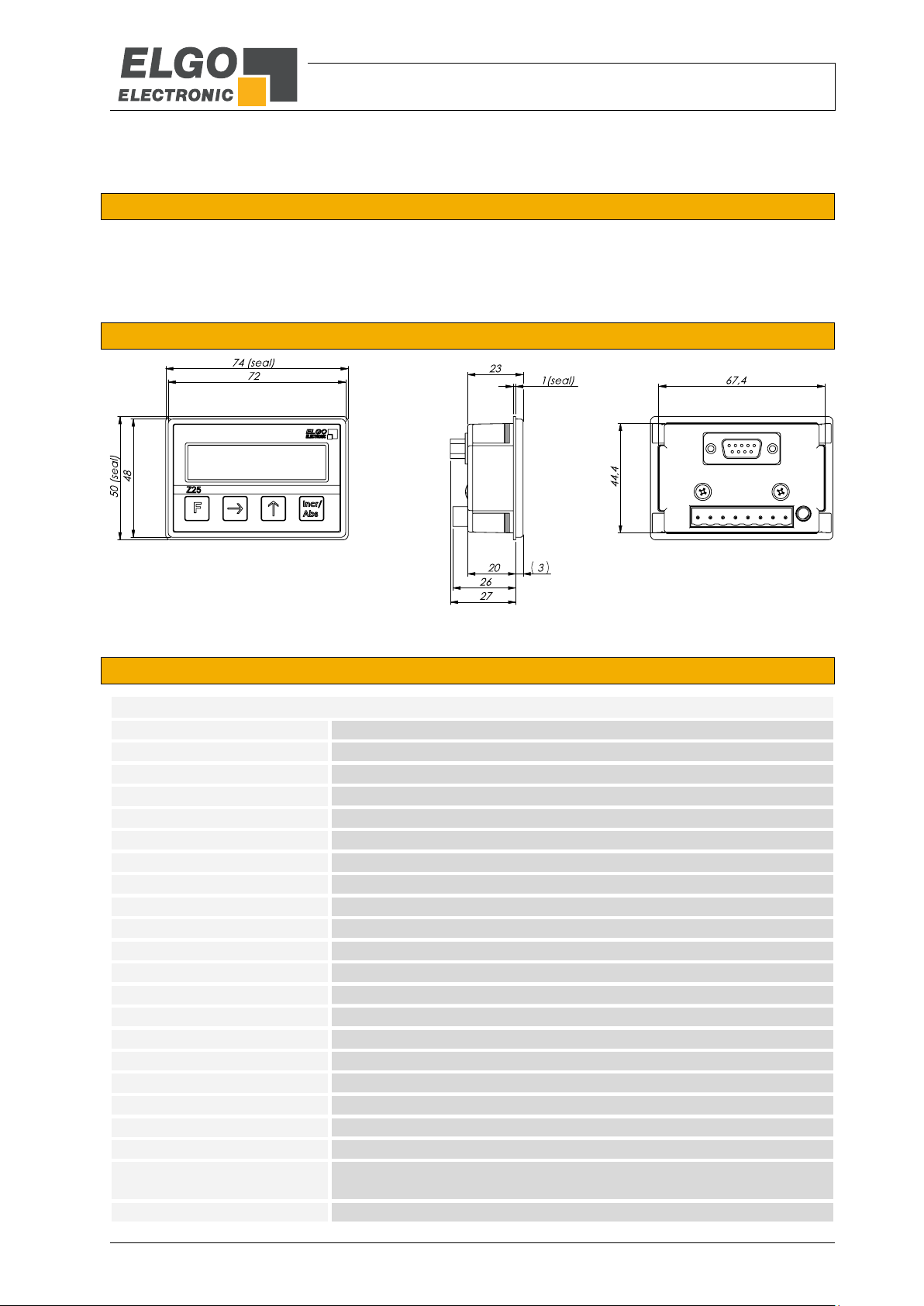
4.2 Dimensions Z25
Figure 1: Z25 dimensions
4.3 Technical Data

Installation and First Start-Up
- 9 -
CAUTION
Please read the operating manual carefully before using the device! Strictly observe the Installation instructions!
In case of damage caused by failure to observe this operating manual, the warranty expires.
ELGO is not liable for any secondary damage and for damage to persons, property or assets.
The operator is obliged to take appropriate safety measures.
The first start-up may only be performed by qualified staff that has been trained and authorized by the operator.
WARNING!
Do not use the device in explosive or corrosive environments!
The device must not be installed close to sources of strong inductive or capacitive interference or strong electrostatic
fields!
CAUTION!
The electrical connections must be made by suitably qualified personnel in accordance with local regulations.
The device may be designed for switchboard mounting. During work on the switchboard, all components must be deenergized if there is a danger of touching the energized parts!
(protection against contacts)
Wiring works may only be performed in the de-energized state!
Thin cable strands have to be equipped with end sleeves!
Before switching on the device, connections and plug connectors have to be checked!
The device must be mounted in a way that it is protected against harmful environmental influences such as splashing
water, solvents, vibration, shock and severe pollution and the operating temperature must not be exceeded.
5 Installation and First Start-Up
5.1 Operating Area

Design and Functions
- 10 -
Function key
Menu navigation for parameter level
Incremental / Absolute switchover
6 Design and Functions
The Z25 unit has 4 front-panel keys. The figure below shows the respective basic functions:
Figure 2: Key assignment of Z25
The functions and key combinations of the keys are described in next section ( 6.3).
6.1 External Inputs
The device has 2 digital control inputs which can be connected via the 8 pin RIA connector S1.
The sensitivity of external input 1 is adjustable by parameter P19 and can be defined “level-sensitive” or “edgesensitive”. The input is 24 VDC / PNP and active with a high level resp. with a positive edge.
The external input 2 is always „level-sensitive“ and cannot be changed. The input is 24 VDC / PNP and active
with a high level.
The function of input 1 can be programmed by using parameter 17 (connector S1/5 9)
The function of input 2 can be programmed by using parameter 18 (connector S1/6 9)
(see parameter description 7).
6.2 Encoder Supply
An encoder supply of 24 VDC is available at Pin 1(-) and 2(+) of both connectors (8 pin RIA connector S1 and
female 9 pin D-SUB connector S2 9). The maximum current load is 300 mA.
Please note: there is no 5 VDC encoder supply available!

Design and Functions
- 11 -
Regular mode:
Press shortly = switching from absolute to incremental measuring
Press shortly = activate tool offsets. (in the absolute mode)
An activated tool offsets are indicated by the digit „1“, shown
in the upper display frame.
+
Press shortly = set to reference value (in the absolute mode)
Press for 3 seconds = change reference value
Switching back to normal mode: Incr/Abs key
+
Press shortly = set to „0“(in the absolute mode)
Press for 3 seconds = change tool offset
Switching back to normal mode: Incr/Abs key
+
Press for 3 seconds = entering the parameter level
Parameter level:
Press shortly = select decade
Press shortly = increase decade
Press shortly = save changes and switch over to next parameter
Input of negative parameters
(negative sign only possible for a value unequal 0)
+
Press for 3 seconds = quit the parameter level
Incr /
Abs
FFF
Incr /
Abs
Incr /
Abs
F
F
Incr /
Abs
6.3 Key Functions
The operation of the device is divided into 2 levels:
Parameter level: For configuration of the main operating parameters ( 7).
User level: Allows access to the basic functions of the unit (depends on software version).
All entries and settings are made exclusively via the 4 front keys or various key combinations.

Parameter Level
- 12 -
7 Parameter Level
This section describes the available parameters and their settings. A parameter list for a quick overview of all
available parameters can be found in the next chapter ( 8). Specific customer settings can be added there.
P01: Counting direction
Up / down switchover (0: forwards, 1: backwards)
P02: Display mode (measurement unit)
Select the desired measurement unit for the display:
0 = mm
1 = inch
2 = m
3 = °
4 = RPM
5 = no measurement unit
P03: Decimal place
To define a decimal place (0 = 1 / 1 = 0.1 / 2 = 0.01 / 3 = 0.001).
P05: Keyboard lock
0 = off
1 = on
P06: Edge evaluation
Settings of edge evaluation can be chosen.
Range: Evaluation of 1 / 2 / 4 edges (0: x 1, 1: x 2, 2: x 4)
P07: Encoder system*
To select the measuring system
0 = Incremental (rotary encoder, LMIX, EMIX, PMIX)
1 = Absolute (EMAX)
2 = Reserved
3 = Reserved
P08: Multiplication factor
A multiplication factor can be defined here.
Range: 00.00001 … 99.99999
P09: Reference value
A reference value can be entered here.
Range: 000000.1 … 999999.9
*) The device must be turned off and on again

Parameter Level
- 13 -
P10: Tool offset
A tool offset can be defined here.
Range: 000000.1 … 999999.9
P11: Saw blade
The saw blade thickness can be entered here.
Range: 0000.1 … 9999.9
P16: Default Initialization
Parameters are reset to default values. (0: not init., 1: default init.)
Enter „1“ and confirm by pressing the „Incr/Abs“ key.
After power off and on again the device has been reset to its default values.
P17: Function of external Input 1
The external input 1 can be programmed as follows:
0 = The input has no function
1 = The input will set the actual value to the defined reference value (P09)
2 = The input will reset the actual value to zero
P18: Function of external Input 2
The external input 2 can be programmed as follows:
0 = The input has no function
1 = The input will add the tool offset (P10) only if P19=0
P19: Trigger for external input 1
0 = Level-sensitive (high)
1 = Edge-sensitive (positive)
P20: Display-Mode
0 = Standard
1 = Rotation speed
3 = Angle
P99: Software version
This parameter displays the software version
*) The device must be turned off and on again

Parameter List
- 14 -
Par. No.
Function
Default setting
Description
Customer settings
P01
Counting direction
0
upwards
P02
Measurement unit (display)
0
mm
P03
Decimal place
1
1 decimal place
P04
Reserved -
P05
Keyboard lock
0
disabled
P06
Edge evaluation
0
1 edge triggering
P07
Encoder system selection
0
Incremental
P08
Multiplication factor
01.00000
P09
Reference value
000000.0
P10
Tool offset
000000.0
P11
Saw blade thickness
0000.0
P12
Reserved -
P13
Reserved -
P14
Reserved -
P15
Reserved -
P16
Default Init 0 not active
P17
Function external input 1
0
not active
P18
Function external input 2
0
not active
P19
Trigger of external input 1
0
level-sensitive
P20
Display mode
0
standard
P21
Reserved -
P22
Reserved -
P23
Reserved -
P24
Reserved
-
P25
Reserved
-
P99
Software version
-
8 Parameter List
Table 1: Parameter List

Connections
- 15 -
Connector S1: 8 pin RIA terminal
Pin
Function
1
0 V / GND (encoder supply output)
2
+24 VDC (encoder supply output)
3
HTL channel A
4
HTL channel B
5
Control input 1 (24 V-PNP)
6
Control input 2 (24 V-PNP)
7
0 V / GND (power supply input)
8
+24 VDC (power supply input)
Connector S2: 9 pin (female) D-SUB
5 V-TTL input signals (with order index 2 11) EMAX / RS422 input signals (order index 5 11)
Pin
Function
Pin
Function
1
0 V / GND (encoder supply output)
1
0 V / GND (encoder supply output)
2
+24 VDC (encoder supply output)
2
+24 VDC (encoder supply output)
3
TTL channel A (5 V levels only)
3
RxD +
4
TTL channel B (5 V levels only)
4
-
5
PE / shield
5 - 6
TTL channel A´ (5 V levels only)
6
RxD −
7
TTL channel B´ (5 V levels only)
7 - 8
TTL channel Z (5 V levels only)
8 - 9
TTL channel Z´ (5 V levels only)
9
-
NOTE!
Only encoders with a 10 … 30 VDC or 24 VDC power supply input can be supplied by
using the encoder supply output. There is no 5 VDC encoder supply available.
Details for earthing and avoiding interferences see in section 10.1
9 Connections
Table 2: Assignment of the RIA terminal
Table 3: Assignment of the D-SUB connector

Disturbances, Maintenance, Cleaning
- 16 -
CAUTION!
The device, the connection line and the signal cable must not be installed next to sources of interference that emit
strong inductive or capacitive interference or strong electrostatic fields.
External perturbations can be avoided thorough suitable cable routing.
The screen of the signal output cable should only be connected to the following Z25 circuit on one side. The figure
shows how the shield is connected to the Z25 position indicator to avoid interference.
The screens should not be grounded on both sides. Signal cables always have to be routed separately from the load
power line. A safety distance of at least 0.5 m has to be kept from inductive and capacitive sources of interference
such as contactors, relays, motors, switching power supplies, clocked controllers etc.!
If interferences occur in spite of all the items stated above being observed, please proceed as follows:
1. Installation of RC-circuits via contactor coils of AC-contactors (e.g. 0,1 µF / 100 Ω)
2. Installation of recovery diodes via DC-inductors
3. Installation of RC-circuits via the different motor phases (in the terminal box of the motor)
4. Do not connect protective earth and ground
5. Connect a mains filter ahead of the external power pack
Error number
Description
Clearance
„Err 110“
Data storage error
Switch the device off and on.
If the error occurs again, return the device for repair.
„Err 210/220“
Sensor error (applies only
with absolute encoders)
Switch the device off and on.
If the error occurs again, check the encoder and its wiring. If
unsuccessful, return the device for repair.
„Err 240“
Power supply voltage
broke down during operation
Switch the device off and on.
If the error occurs again, check the power source resp. power
pack. If unsuccessful, return the device for repair.
„Err 250“
Power supply voltage
broke down at power on
Switch the device off and on.
If the error occurs again, check the power source resp. power
pack. If unsuccessful, return the device for repair.
Signal Cable
Shield
PE
Earthing Connection
10 Disturbances, Maintenance, Cleaning
This chapter describes possible causes for disturbances and measures for their removal. In case of increased disturbances, please follow the
measures for fault clearance in chapter 10.1. In case of disturbances that cannot be eliminated by following the advice and the fault clearance measures given here, please contact the manufacturer (see second page).
10.1 Interferences and Fault Clearance
10.2 Possible Errors and their Clearance
The following table shows possible errors and their clearance.
Table 4: Error messages and clearance

Disturbances, Maintenance, Cleaning
- 17 -
WARNING!
Danger of injury through non-conventional fault clearance!
Non-conventional fault clearance can lead to severe injuries and damage of property.
Therefore:
Any work to clear the faults may only be performed by sufficiently qualified staff
Arrange enough space before starting the works
Make sure that the mounting area is clean and tidy. Loose components and tools are sources of accidents.
If components need to be replaced:
Pay attention to a correct installation of the spare parts.
Reinstall all the fixing elements properly
Before turning on the device, ensure that all covers and safety equipment is installed correctly and functions
properly
WARNING!
Danger through non-conventional maintenance!
Non-conventional maintenance can lead to severe injuries and damage of property.
Therefore:
Maintenance works may only be completed by staff that has been authorized and trained by the operator.
WARNING!
The device can only be cleaned with a damp cloth, do not use aggressive cleanser!
10.3 Re-start after Fault Clearance
After the fault clearance:
1. Reset the emergency stop mechanism if necessary
2. Reset the error report at the super-ordinate system if necessary.
3. Ensure that there are no persons in the danger area.
4. Follow the instructions from chapter 5.
10.4 Maintenance
The device is maintenance-free.
10.5 Cleaning

Type designation
- 18 -
NOTE
When ordering, please use the here described ordering code (Type Designation). Options
that are not required are filled in with „-„.
Order Designation
Description
NG24.0
External 24 VDC power pack (primary 115/230 VAC) as power supply for Z25
Z25 024
Device type:
Z25 = 1 Axis Position Indicator
Power supply voltage:
024 = 24 VDC
Signal inputs:
0 = A, B / 24 VDC encoder supply / 24 V-HTL levels (PNP)
2 = A, A’, B, B’, Z, Z’ / 24 VDC encoder supply / 5 V-TTL levels (PNP)
5 = Adaption to ELGO-422 interface for EMAX absolute linear encoder
Version:
000 = Standard version
001 = 1. customized version
002 = 2. customized version (etc.)
X--- 000
11 Type designation
11.1 Accessories
Table 5: Accessories

Index
- 19 -
12 Index
Abs/Incr .......................................................... 11
Accessories ..................................................... 18
Accident prevention regulations........................... 4
Causes of risk .................................................... 5
Cleaning ................................................... 16, 17
Connections .................................................... 15
Conventional use ............................................... 6
Demounting ...................................................... 5
Device number .................................................. 8
Dimensions Z25 ................................................ 8
Disposal............................................................ 5
Disturbances ................................................... 16
edge evaluation ............................................... 12
Encoder Supply ................................................ 10
Errors and clearance ........................................ 16
Explanation of symbols ....................................... 4
External Inputs ................................................. 10
Fault clearance .......................................... 16, 17
First start-up ...................................................... 9
Identification ..................................................... 8
Installation ........................................................ 9
Key Functions .................................................. 11
Maintenance ............................................. 16, 17
Operating area ................................................. 9
Operational safety ............................................. 4
Order reference ................................................ 8
Packaging material ............................................ 6
Parameter Level......................................... 11, 12
Parameter List ................................................. 14
Product features ................................................ 7
Product Features ............................................... 7
Protection against contact .................................. 9
Protective equipment ......................................... 5
Reference value ............................................... 11
Regular modes ................................................ 11
Safety ........................................................... 4, 5
Safety instructions .............................................. 4
Safety rules ....................................................... 4
Start-up ............................................................ 9
Storage ............................................................ 6
Technical Data .................................................. 8
Tool offset ...................................................... 11
Transport .......................................................... 6
Transport damage ............................................. 6
Type designation ............................................... 8

- 20 -
Document- No.:
799000592 / Rev. 4
Document- Name:
Z25-000-MA-E_17-19
Subject to change - © 2017
ELGO Electronic GmbH & Co. KG
EL G O Electron i c GmbH & Co. KG
Me as uri ng | Po sit ion ing | C ont rol
Carl - Benz - Str. 1, D -782 39 R iela sing en
Fon:+49 (0) 7731 9339-0, Fax:+49 (0) 7731 28803
Internet: www.elgo.de, Mail: i nfo@elgo.de
 Loading...