

ELGO Electronic P40-SN002 Series Operation Manual

Operation Manual
Series P40-SN002
Application metal shears
Programmable controller
LCD Display
Simple handling
Manual inching function
Single set operation
Program memory
Digital outputs
Analog Output

Contents
- 2 -
Content
1. General Information ....................................................................................................... 4
1.1. Information Operation Manual ............................................................................. 4
1.2. Explanation of Symbols ......................................................................................... 4
1.3. Statement of Warranties ....................................................................................... 5
1.4. Demounting and Disposal ..................................................................................... 6
2. Safety .............................................................................................................................. 7
2.1. General Cause of Risks ......................................................................................... 7
2.2. Personal Protective Equipment .............................................................................. 7
2.3. Conventional Use ................................................................................................. 8
3. Transport and Storage ................................................................................................... 8
3.1. Safety Instructions for Transport/Unpacking and Loading ...................................... 8
3.2. Handling of Packaging Material ............................................................................ 8
3.3. Check of Transport ............................................................................................... 9
3.4. Storage ................................................................................................................ 9
4. Product Features ........................................................................................................... 10
5. Technical Data .............................................................................................................. 11
5.1. Dimensions ......................................................................................................... 12
6. Configuration and Functions ........................................................................................ 13
6.1. Elements ............................................................................................................. 13
6.1.1. Control Elements ....................................................................................................... 13
6.1.2. Display Elements ....................................................................................................... 13
6.1.3. Function of Keys ........................................................................................................ 14
6.2. Menu, sections and parameters .......................................................................... 15
6.2.1. Axis Menu / Distances ............................................................................................... 16
6.2.1.1. Distance / Longitudes Parameters ............................................................................... 17
6.2.2. Axis menu / times ...................................................................................................... 21
6.2.3. Axis menu / analog ................................................................................................... 23
6.2.3.1. Analog parameters ................................................................................................... 24
6.2.4. Axis menu / General ................................................................................................. 26
6.2.4.1. System parameters .................................................................................................... 27
6.2.5 Material Table .................................................................................................................... 31
6.2.5.1 Explanation of the Interpolation .................................................................................... 31
6.2.6 Menu / System .......................................................................................................... 32
6.3. Machine setting .................................................................................................. 34
6.3.1. Gap Setup (Cut gap) ................................................................................................. 34
6.3.2. Angle Setup (cut angle) .............................................................................................. 34
6.4 Configuration of inputs and outputs .................................................................... 35
6.4.1. Link-up the inputs with functions .......................................................................................... 35
6.4.2. Allocation to the logic input functions .................................................................................. 35
6.4.3. Linking the outputs of functions ........................................................................................... 35
6.4.4. Logic Allocation to Outputs ................................................................................................ 35

Contents
- 3 -
7. Operation ....................................................................................................................... 36
7.1 Operation Modes .............................................................................................................. 36
7.1.1 Manual mode .................................................................................................................... 36
7.1.2 Single mode ....................................................................................................................... 36
7.1.3 Program mode ................................................................................................................... 36
7.1.3.1 Input of a program .......................................................................................................... 36
7.1.3.2. Handle of a program .................................................................................................. 37
7.1.4 Reference....................................................................................................................... 37
7.1.4.1 Function of reference drive ........................................................................................... 37
7.2 Connector pin assignment .................................................................................. 38
7.2.1 Overview Terminal Assignment ...................................................................................... 39
7.3 Diagnostics ....................................................................................................................... 40
8. Interferences .................................................................................................................. 41
8.1 Security .............................................................................................................. 41
8.2 Electrical interference suppression ....................................................................... 42
8.3 Restart after fault clearance ................................................................................ 42
8.4 EMC information ................................................................................................ 43
9 Maintenance ................................................................................................................. 44
10 Type Designation ......................................................................................................... 45
11 Accessories .................................................................................................................... 46
- 4 -
1. General Information
1.1. Information Operation Manual
The manual contains important information regarding the handling of the controller.
Precondition for safe operation is the compliance with the specified safety and handling instructions.
Moreover, observe the existing local accident prevention regulation and general safety rules.
Please read the operation manual carefully before starting to work. The manual should be kept accessible at
anytime. The illustrations in the manual are for better representation of the facts they are not necessarily to
scale and can be slightly different to the actual construction.
1.2. Explanation of Symbols
Warning notices
Warning notices are characterized by symbols in the operation manual.
The notes will be introduced by signal words to express the magnitude of the danger.
Follow these advices in order to avoid accidents and injuries to persons and property.
DANGER!
... adverts to direct dangerous situations that can lead to death or severe injuries.
CAUTION!
... advices to potentially dangerous situations that can lead to death or severe
injuries.
ATTANTION!
... advices to potentially dangerous situations that can lead to damages on
property.
General Information
- 5 -
Hints and commendations
ADVERT!
...highlights helpful hints and recommendations for efficient and failure-free
operation.
Specific safety instructions
The following symbols in conjunction with safety instructions are used in order to point out possible hazards:
DANGER!
...marks perilous situations by electricity. By non-observance of the safety
instructions the possibility of death or severe injuries exist. The operations have to be
carried out only by an electrician.
General Information
1.3. Statement of Warranties
The warranty conditions are in a separate document.
Guarantee
The producer guarantees the functional capability of the process engineering and the selected parameter.
The period of warranty is one year and begins with the date of delivery.

General Information
- 6 -
1.4. Demounting and Disposal
Unless otherwise authorized, dispose the item considering the safety instructions.
Before demounting
Disconnect the power supply
Secure against re-start
Disconnect supply lines physically and discharge remaining energy
Dispose operating supplies with respect to the environment
Disposal
Recycle the decomposed elements:
Scrap metal elements
Recycle plastic parts
Dispose the rest of the components according to their material consistence
ATTENTION!
Wrong disposal Î damage caused to the environment!
Electronic waste, electronic components, lubricants and operating supplies are
liable to treatment of hazardous waste.
Only approved specialized companies should perform disposal.
Local authorities and waste management facilities provide information about environmentally suitable
disposal.

- 7 -
2. Safety
2.1. General Cause of Risks
This chapter gives an overview about all important safety aspects to guarantee an optimal protection of
employees.
Non-observance of the instructions mentioned in this operation manual can result in hazardous situations.
2.2. Personal Protective Equipment
Employees should wear protective clothing during installation of the device to minimize the risk of accidents.
Therefore:
Change into protective clothing before beginning the work process. Also observe any labels in the operating
area regarding protective clothing.
Protective clothing
Safety working clothing
... is close-fitting
... is tear proof
... has tight sleeves without distant parts
Also wear no rings, necklaces or other jeweler.
Protective gloves
... for protecting the hands against abrasion and cuts
Safety
Conventional use, Transport, Storage
- 8 -
2.3. Conventional Use
The controller P40 is for the limited purpose as described in this manual:
The controller P40 is constructed for positioning uses only.
CAUTION!
Danger through non-conventional use!
Non-intended use and non-observance of this operation manual can lead to dangerous
situations.
Therefore:
Use P40 only as described
Strictly follow this manual
Avoid in particular:
Remodeling, refitting or changing of the device or parts of it with the intention to alter
functionality or scope of the position controller.
ELGO is not liable for any damages resulting from improper use of the product.
3. Transport and Storage
3.1. Safety Instructions for Transport/Unpacking and Loading
ATTENTION!
Professional transport only.
Do not throw, hit or fold the package.
3.2. Handling of Packaging Material
Adverts for proper disposal refer to 1.4.

Conventional use, Transport, Storage
- 9 -
3.3. Check of Transport
Examine delivery immediately after receiving for completeness and transport damages.
In case of externally recognizable transport damages:
Do not accept the delivery or do accept under reserve
Note extent of damages on the transportation documents or on the delivery note
File complaint immediately
ADVERT!
Claim any damages you recognize as soon as possible. The claims for damage must be
filed in the lawful reclaim periods.
3.4. Storage
Store device only under following conditions:
Do not store outside
Keep dry and dust-free
Do not expose to aggressive media
Protect from direct sun light
Avoid mechanical shocks
Storage temperature: 20 to + 50 °C
Relative humidity: 60% non-condensing
Inspect packages regularly if stored for an extensive period of time (> 3 months)
Product Features
- 10 -
4. Product Features
Essential features:
Analog or digital outputs for 1 - 3 speed operation
16 free programmable digital in-/outputs
Program memory (1000 sets)
Angle control / gap control / backgauge
Limitation of the cutting length
Material List for angle and gap control
The single axis controller of P40 series is applicable
to easy positioning tasks. An important feature is the
easy structured function menu. It allows a quick and
comfortable setting of the target value, if necessary
a specific quantity of desired pieces, an angle or the
gap. Target and actual value of the axes plus
quantity will be displayed on the front panel. The
keyboard is simple and user-friendly. With the inputs
the cutting angle or gap can be displayed and
controlled. These encoder inputs work in an analog
mode. A back stop can be programmed. The P40
series has an internal program memory with up to
1000 lines. For the positioning two different kinds of
output signals are available: Switch mode
positioning and PID-analog output. The P40 series
can alternatively be supplied with 24VDC or 24VAC.
An optional serial interface allows data transmission
for communication with a superior system.
Basic modes of operation:
The P40 consists of three general operation modes:
1. Manual: Inching operation moves the axes through operating the keypad or external switches.
2. Single: A whole set can be worked off.
3. Program: In this operation mode a programmed set can be worked off.

Technical Data
- 11 -
5. Technical Data
P40 – ELGO-position controller
Input supply voltage 24 VDC
Power input 24 VDC; max. 150 mA (no-load condition)
Rotary encoder supply unit 24 VDC or 5VDC ; max. 130 mA
Analog input (option) 12 Bit resolution ; 3,3 V Supply measuring system
Input signals The Pin assignment of the inputs and the input logic are programmable
Minimum pulse duration: 300 ms
Input current /Pin: max. 10 mA
Output signals The Pin assignment of the outputs and the output logic are programmable
Open Emitter (PNP)
Complete short-circuit-proof
Output current: max. 80 mA
Recovery diode is integrated
Actual value memory E² Prom
Durability: 105 On-Off-Switch-Cycle or 10 years
Connection technology Phoenix Connectors
Displays LCD Dot-Matrix 128 x 80 mm with white backlight
Hardware 32-Bit-Microprocessor with 1 MByte Flash 56 Kbyte RAM
System accuracy +/ -1 Increment
Input frequency
15 KHz (upgrade on enquiry possible) equals by 0,1 mm resolution: 120
m/min. (2 m/s)
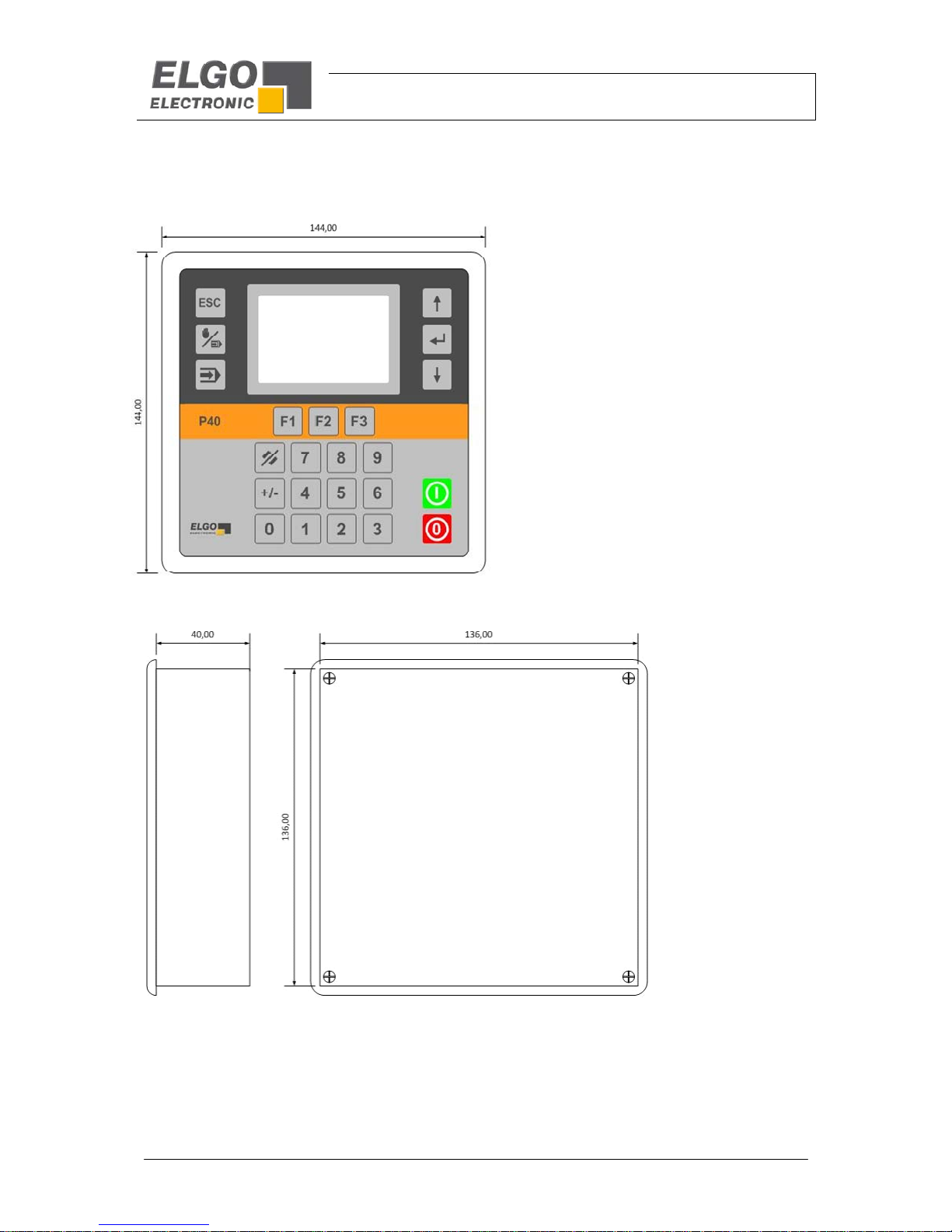
Housing dimensions W x H x D = 144 mm x 144 mm x 40 mm (without connector)
Disruption degree W x H = 136 mm x 136 mm
Installation depth without
connector
40 mm
Installation depth with
connector
75 mm
Ambient temperature 0 to +45 °C
Technical Data
- 12 -
5.1. Dimensions
Configuration and Functions
- 13 -
6. Configuration and Functions
6.1. Elements
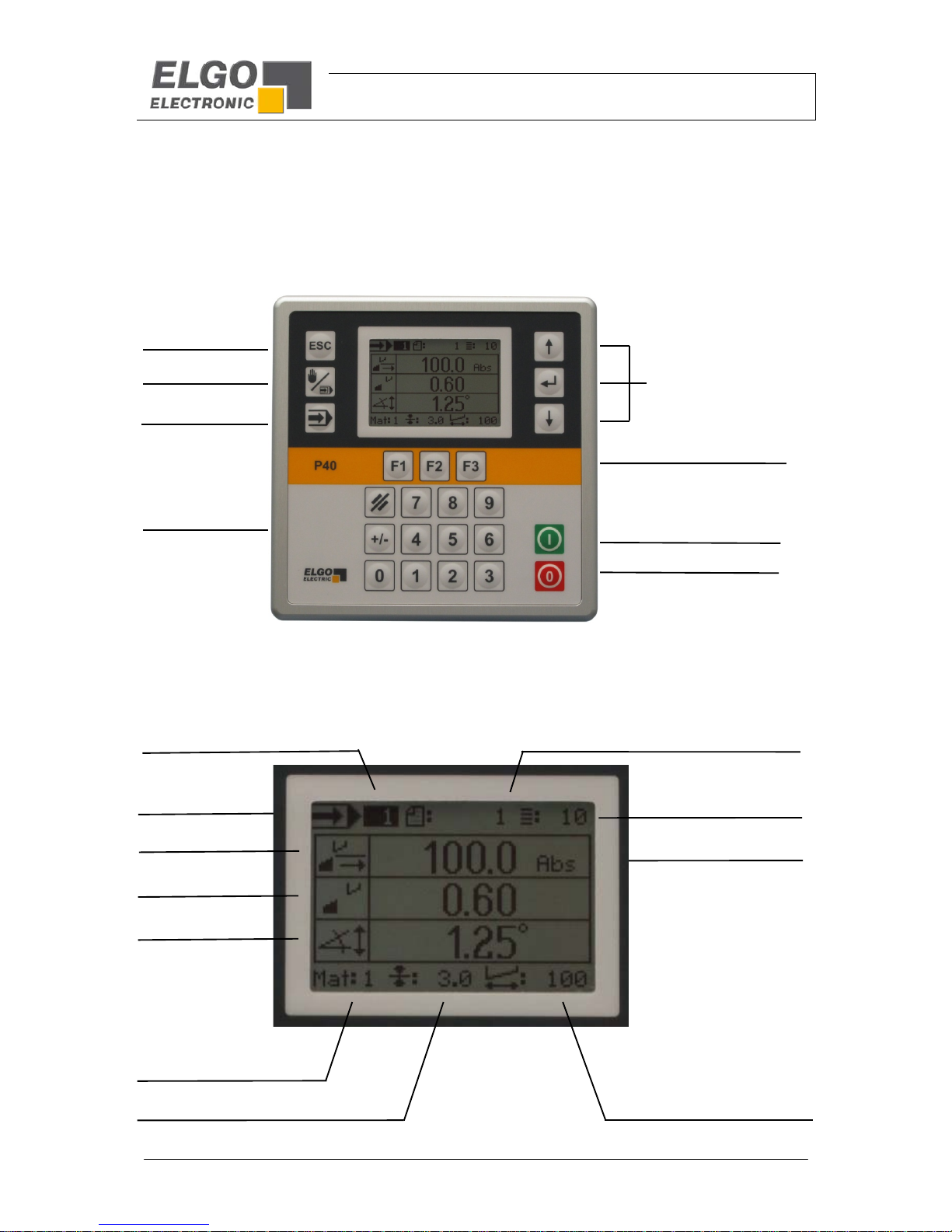
6.1.1. Control Elements
6.1.2. Display Elements
Menu navigation
Forward/backward/Enter
Start
Sto
p
Escape
Manual/Single
Function keys
Input
Program-Mode
Cutting Length
Position Mode
Material Thickness
Symbol Operation
mode
Material
Quantity
Set Number
Backgauge
Gap
Angle
Program Number
Configuration and Functions
- 14 -
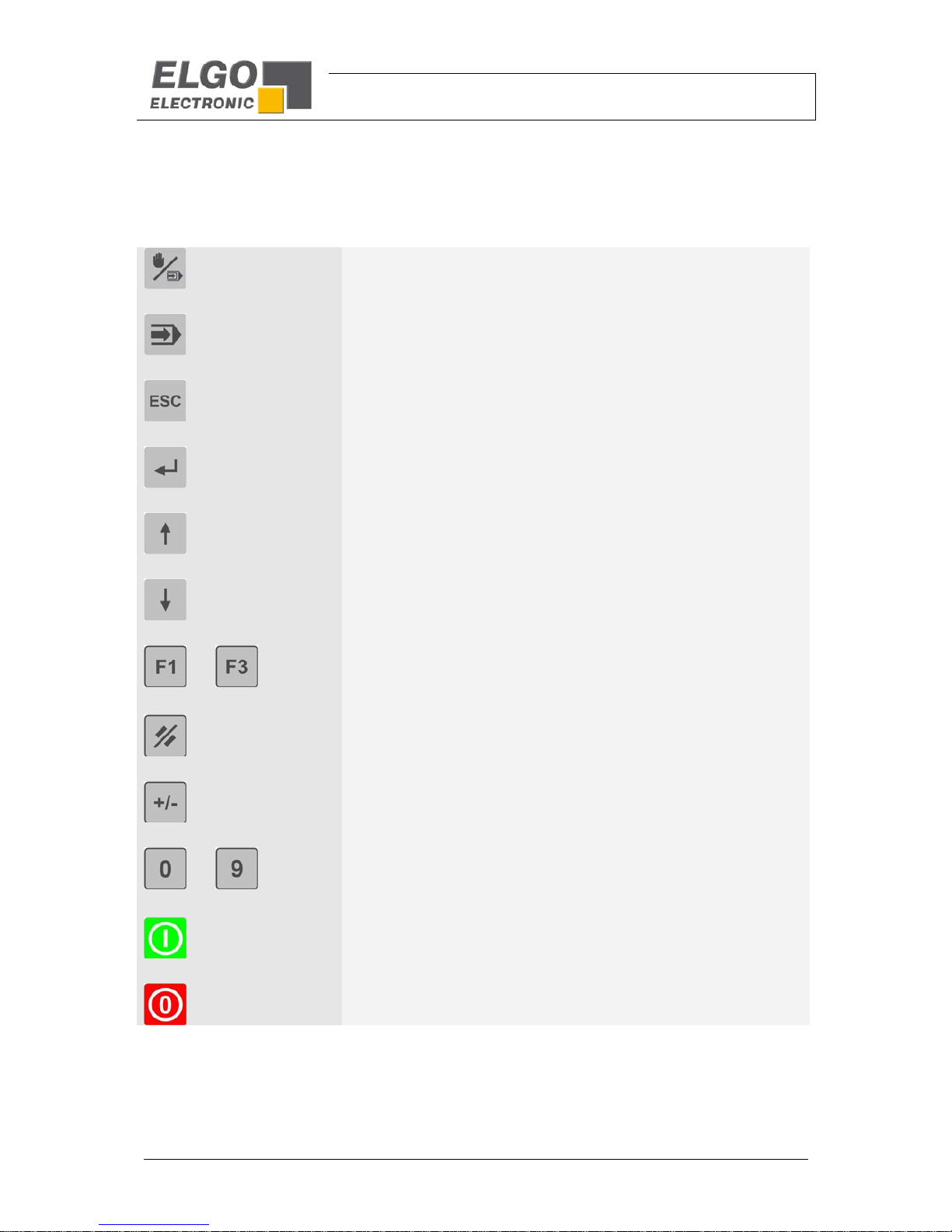
6.1.3. Function of Keys
Change Operation mode between „Manual“ and „Single“
Operation Mode “Program”
Leaving an Operation Mode or a Sub menu
Select or Confirm
Cursor navigation „up“
Cursor navigation „down“
...
Function keys (addicted to Menu or Operation mode)
Clear or reset an input
Change of Sign
...
Enter Target Value or Parameter value
Start Positioning
Stop Positioning
 Loading...