

Operating Manual
SERIE LMIX22
Magnetic incremental Length Measuring System with selectable resolution
With periodic index pulse or optional reference pulse
Distance between sensor / magnetic tape of up to 2.0 mm
Differential HTL or TTL Line Driver outputs
Various resolution at 4 edge triggering available (specified by order)
Repeat accuracy ± 1 increment
Small sensor with integrated evaluation electronic (translator)
Speed proportional output of the square wave signals
799000609 / Rev. 7 / 2017-05-12
Translation of the original operating manual

- 2 -
Publisher
ELGO Electronic GmbH & Co. KG
Carl-Benz-Str. 1
D-78239 Rielasingen-Worblingen
Technical Support
+49 (0) 7731 9339 – 0
+49 (0) 7731 2 13 11
info@elgo.de
Document- No.
799000609
Document- Name
LMIX22-000-MA-E_19-17
Document- Revision
Rev. 7
Issue Date
2017-05-12
Copyright
© 2017, ELGO Electronic GmbH & Co. KG

Contents
- 3 -
1 Contents
1 Contents ..................................................................................................... 3
2 Image Directory ......................................................................................... 5
3 Table Directory ........................................................................................... 5
4 General, Safety, Transport and Storage .................................................... 6
4.1 Information Operating Manual ........................................................................................... 6
4.2 Explanation of Symbols ...................................................................................................... 6
4.3 Statement of Warranties ..................................................................................................... 6
4.4 Demounting and Disposal .................................................................................................. 7
4.5 General Causes of Risk ..................................................................................................... 7
4.6 Personal Protective Equipment ............................................................................................ 7
4.7 Conventional Use ............................................................................................................. 8
4.8 Safety Instructions for Transport, Unpacking and Loading ....................................................... 8
4.9 Handling of Packaging Material .......................................................................................... 8
4.10 Inspection of Transport ...................................................................................................... 8
4.11 Storage ........................................................................................................................... 8
5 Product Features ........................................................................................ 9
5.1 Version LMIX22-007 ......................................................................................................... 9
5.2 Version LMIX22-027 ......................................................................................................... 9
5.3 Functional Principle ......................................................................................................... 10
5.4 Pulse Diagram ................................................................................................................ 10
6 Technical Data ......................................................................................... 11
6.1 Identification .................................................................................................................. 11
6.2 Dimensions Sensor .......................................................................................................... 11
6.3 Dimensions of Guiding Profile and End / Connection Profile ................................................. 12
6.4 Technical Data Sensor ..................................................................................................... 13
6.5 Technical Data Magnetic Tape ......................................................................................... 14
6.6 Sensor position (active sensor area) ................................................................................... 15
7 Installation and First Start-Up ................................................................. 16
7.1 Operating Area .............................................................................................................. 16
7.2 Description installation / Mounting of the Magnetic Tape ..................................................... 16
7.3 Installation of the Sensor .................................................................................................. 21
7.4 Installation of the Magnetic Angle MW-007 for Version LMIX22-007 ..................................... 23
7.5 Offset ............................................................................................................................ 23
7.6 Activation of the Device ................................................................................................... 23
8 Overview: Versions with and without Reference Pulse ............................ 24
8.1 Version 000 (standard) .................................................................................................... 24
8.2 Version 007 ................................................................................................................... 24
8.3 Version 027 ................................................................................................................... 24

Contents
- 4 -
9 Extended temperature range (option T) .................................................. 25
9.1 Magnetic tape fixation with option T .................................................................................. 25
9.2 Prefabricated magnetic tape for option T ............................................................................ 25
10 Connections .............................................................................................. 26
11 Disturbances, Maintenance, Cleaning ..................................................... 27
11.1 Fault Clearance .............................................................................................................. 27
11.2 Re-start after Fault Clearance ........................................................................................... 27
11.3 Maintenance .................................................................................................................. 28
11.4 Cleaning ....................................................................................................................... 28
12 Type Designation ..................................................................................... 29
12.1 Type Designation Sensor .................................................................................................. 29
12.2 LMIX22 Resolutions ......................................................................................................... 29
12.3 Type Designation Magnetic Tape ...................................................................................... 30
12.4 Type Designation Guide Profile FBK80 .............................................................................. 30
12.5 Accessories .................................................................................................................... 31
13 Index ........................................................................................................ 35

Contents
- 5 -
2 Image Directory
Figure 1: Magnetic Tape ......................................................................................................................... 10
Figure 2: Pulse diagram .......................................................................................................................... 10
Figure 3: Dimensions LMIX22 sensor ........................................................................................................ 11
Figure 4: Dimensions FBK80 ................................................................................................................... 12
Figure 5: Dimensions AFBK 80 ................................................................................................................ 12
Figure 6: Sensor position with horizontal installation .................................................................................. 15
Figure 7: Sensor position with vertical installation ...................................................................................... 15
Figure8: Components of the magnetic tape .............................................................................................. 17
Figure 9: Magnetic Tape MB20-20-10-1(2)-R-D-BK80 .............................................................................. 17
Figure10: Handling ................................................................................................................................ 18
Figure 11: Magnetic tape variants ............................................................................................................ 20
Figure 12: Magnetic tape variants with FBK80 .......................................................................................... 20
Figure 13: Sensor - mounting options ....................................................................................................... 21
Figure 14: Installation of horizontal standard version ................................................................................. 21
Figure 15: Installation of vertical version (Option L) ................................................................................... 21
Figure 16: Tolerances ............................................................................................................................. 22
Figure 17: Installation of magnetic angle MW-007 for special version LMIX22-007...................................... 23
Figure 18: Overview (standard version) .................................................................................................... 24
Figure 19: Overview (version 007) ........................................................................................................... 24
Figure 20: Overview (version 027) ........................................................................................................... 24
Figure 21: Magnetic tape with punched holes ........................................................................................... 25
3 Table Directory
Table 1: Chemical Influences ................................................................................................................... 19
Table 2: Tolerances ................................................................................................................................ 22
Table 3: Pin assignment with open cable ends ........................................................................................... 26
Table 4: Pin assignment with option D1 (ELGO standard) .......................................................................... 26
Table 5: Pin assignment with option D2 (18.50) ........................................................................................ 26
Table 6: Pin assignment with option D3 (round connector suitable for SKA-1 resp. MIX) ................................ 26
Table 7: LMIX22 Resolutions .................................................................................................................... 29
Table 8: Accessories ............................................................................................................................... 31

General, Safety, Transport and Storage
- 6 -
DANGER!
This symbol in connection with the signal word “Danger” indicates an immediate danger for the life and health of
persons. Failure to heed these instructions can result in serious damage to health and even fatal injury.
WARNING!
This symbol in connection with the word „Warning” means a possibly impending danger for the life and health of
persons. Failure to heed these instructions can result in serious damage to health and even fatal injury.
CAUTION!
This symbol in connection with the signal word “Caution” indicates a possibly dangerous situation. Failure to heed
these instructions can lead to minor injuries or damage of property.
DANGER!
This symbol in connection with the signal word “Danger” indicates an immediate danger for the life and health of
persons due to voltage.
Failure to heed these instructions can result in serious damage to health and even fatal injury. The operations may
only be carried out by a professional electrician.
NOTE!
…points out useful tips and recommendations as well as information for an efficient and trouble-free operation.
4 General, Safety, Transport and Storage
4.1 Information Operating Manual
This manual contains important information regarding the handling of the device. For your own safety and operational safety, please observe all safety warnings and instructions.
Precondition for safe operation is the compliance with the specified safety and handling instructions. Moreover, the existing local accident
prevention regulations and the general safety rules at the site of operation have to be observed.
Please read the operating manual carefully before starting to work with the device! It is part of the product and should be kept close to the
device and accessible for the staff at any time. The illustrations in the manual are for better demonstration of the facts. They are not necessarily to scale and can slightly differ from the actual design.
4.2 Explanation of Symbols
Special notes in this manual are characterized by symbols. The notes are introduced by signal words which express the magnitude of danger.
Please follow this advice and act carefully in order to avoid accidents, damage, and injuries.
Warning notes:
Special safety instructions:
Tips and recommendations:
Reference marks:
Marks a reference to another chapter of this manual.
Marks a reference to another chapter of another document.
4.3 Statement of Warranties
The producer guarantees the functional capability of the process engineering and the selected parameters.
General, Safety, Transport and Storage
- 7 -
CAUTION!
Wrong disposal causes environmental damages!
Electronic scrap, electronic components, lubricants and other auxiliary materials are subject to special refuse and can
only be disposed by authorized specialists!
CAUTION!
Please read the operating manual carefully, before using the device! Observe the installation instructions! Only start
up the device if you have understood the operating manual. The operating company is obliged to take appropriate
safety measure.
The initial operation may only be performed by qualified and trained staff.
Selection and installation of the devices as well as their embedding into the controlling system require qualified
knowledge of the applicable laws and normative requirements on the part of the machine manufacturer.
PROTECTIVE CLOTHING
… is close-fitting working clothing with light tear strength, tight sleeves and without distant parts. It serves preliminarily for protection against being gripped by flexible machine parts.
Do not wear rings, necklaces or other jewellery.
PROTECTIVE GLOVES
…for protecting the hands against abrasion, wear and other injury of the skin.
PROTECTIVE HELMET
…for protection against injuries of the head.
4.4 Demounting and Disposal
Unless acceptance and disposal of returned goods are agreed upon, demount the device considering the safety instructions of this manual
and dispose it with respect to the environment.
Before demounting, disconnect the power supply and secure against re-start. Then disconnect the supply lines physically and discharge
remaining energy. Remove operational supplies and other material.
Disposal:
Recycle the decomposed elements: Metal components in scrap metal, Electronic components in electronic scrap, Recycle plastic components, dispose the remaining components according to their material consistence.
Local authorities and waste management facilities provide information about environmentally sound disposal.
Safety
4.5 General Causes of Risk
This chapter gives an overview of all important safety aspects to guarantee an optimal protection of employees and a safe and trouble-free
operation. Non-observance of the instructions mentioned in this operating manual can result in hazardous situations.
4.6 Personal Protective Equipment
Employees have to wear protective clothing during the installation of the device to minimize danger of health.
Therefore:
Change into protective clothing before performing the works and wear them throughout the process.
Additionally observe the labels regarding protective clothing in the operating area.
Protective clothing:
General, Safety, Transport and Storage
- 8 -
CAUTION!
Danger through non-conventional use!
Non-intended use and non-observance of this operating manual can lead to dangerous situations.
Therefore:
Only use the device as described
Strictly follow the instructions of this manual
Avoid in particular:
Remodelling, refitting or changing of the construction or single components with the intention to alter the
functionality or scope of the device.
CAUTION!
Transport the package (box, palette etc.) professionally.
Do not throw, hit or fold it.
NOTE!
Claim any damage immediately after recognizing it. The claims for damage must be filed in the lawful reclaim periods.
4.7 Conventional Use
The ELGO-device is only conceived for the conventional use described in this manual.
The ELGO LMIX22 length measuring system only serves to measure lengths.
Claims resulting from damages due to non-conventional use are not possible.
Only the operator is liable for damages caused by non-conventional use.
4.8 Safety Instructions for Transport, Unpacking and Loading
4.9 Handling of Packaging Material
Notes for proper disposal: 4.4
4.10 Inspection of Transport
Check the delivery immediately after the receipt for completeness and transport damage.
In case of externally recognizable transport damages:
Do not accept the delivery or only accept under reserve.
Note the extent of damages on the transportation documents or delivery note.
File complaint immediately.
4.11 Storage
Store the device only under the following conditions:
Do not store outside
Keep dry and dust-free
Do not expose to aggressive media
Protect from direct sun light
Avoid mechanical shocks
Storage temperature (6) needs to be observed
Relative humidity (6) must not be exceeded
Inspect packages regularly if stored for an extensive period of time (>3 months)

Product Features
- 9 -
5 Product Features
The length measuring system LMIX22 bases on the proven LMIX encoder system. The system extends the existing
LMIX product series and offers two considerable advantages:
The resolution can be freely selected ( 0)
The sensor is also available with a unique reference pulse ( 5.1 resp. 5.2)
Overview of features:
Distance between sensor / magnetic tape up to 2.0 mm
Differential HTL or TTL Line Driver Outputs
Various resolution with 4 edge triggering available (order designation)
Repeat accuracy +/- 1 increment
Small sensor with integrated evaluation electronic (translator)
Speed proportional output of square-wave signals
Periodic index pulse every 5 millimeters (standard version) or
optional reference pulse output (versions 007 and 027) available
Despite the small dimensions the evaluation electronic (translator) is integrated in the sensor head. Optionally, a
vertically mountable LMIX22 variant is available. This must be specified as option “L” with the order ( 12.1).
Please note the following when ordering option “L”:
The position of the internal sensor board is displaced by 90°. So a horizontal mounting, respectively sensing is
no longer possible!
Further information about the mounting positions:
Standard: horizontal installation ( 7.3.2.1)
Option L: vertical installation ( 7.3.2.2)
5.1 Version LMIX22-007
Instead of a periodical index pulse (channels Z / Z‘), a single reference pulse (channels R / R‘) occurs at the
position where the magnet angle MW-007 (accessorial part 12.5) is installed. For more information refer to
sections 7.4 and 8.2.
5.2 Version LMIX22-027
Instead of a periodical index pulse (channels Z / Z‘), a single reference pulse (channels R / R‘) occurs at a desired position of the magnetic tape ( 8.3). In this case, a dual track magnetic tape (type MB20-50-10-2) must
be used. The desired reference pulse position can be ordered by using the type designation of the magnetic
tape ( 12.3). See also example 8.3.
Product Features
- 10 -
N NS S N N N NS S S S N NS SN NS S N N N NS S S S N NS S
B
B‘
Z
Z‘
A
A‘
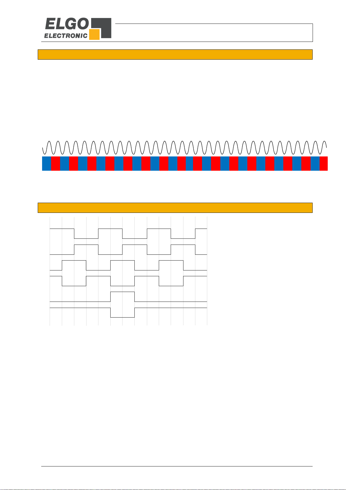
The channels A and B are phase
shifted by 90 degrees.
The index pulse output occurs
periodically every 5 mm or optionally as a free definable reference pulse (R / R’).
5.3 Functional Principle
The basis of the magnetic incremental encoders consists of a scanning technology, which scans the north and
south poles on the coded magnetic tape and produces a single Sine/Cosine wave for each pole. The complete
sine/cosine signal process is interpolated electronically. Depending on refinement of the interpolation, together
with the pole distance of the magnetic tape, the resolution of the measuring system is determined.
A special evaluation electronic (translator) processes the sine/cosine wave into square output signals from the
signal information of the magnetic tape. These square signals are equivalent to conventional optical rotary- or
linear encoder outputs.
The translator circuit of the LMIX22 measuring system is already integrated in the sensor head.
Figure 1: Magnetic Tape
5.4 Pulse Diagram
Figure 2: Pulse diagram
Technical Data
- 11 -
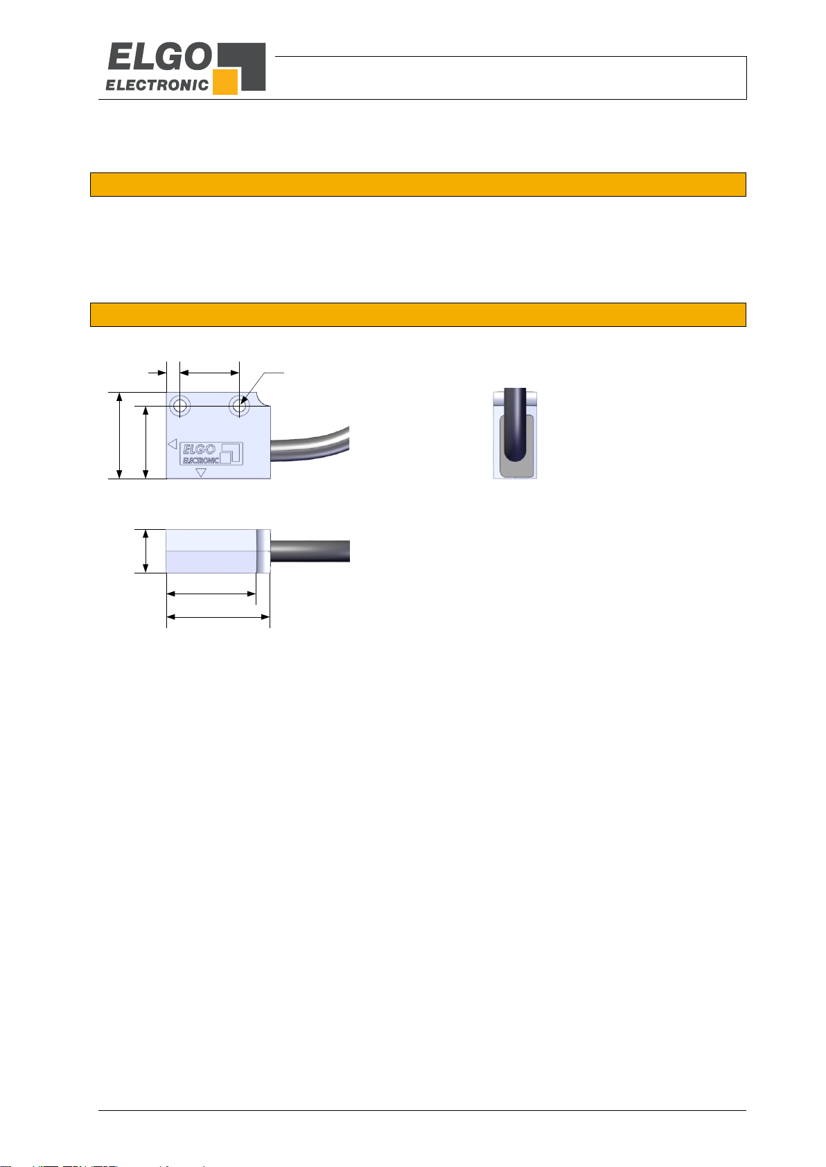
30
12.5
17
4
21
25
25
Ø3.4
6 Technical Data
6.1 Identification
The type label serves for the identification of the unit. It is located on the housing of the sensor and gives the
exact type designation (=order reference, see type designation) with the corresponding part number.
Furthermore, the type label contains a unique, traceable device number.
When corresponding with ELGO always indicate this data.
6.2 Dimensions Sensor
Figure 3: Dimensions LMIX22 sensor

Technical Data
- 12 -
320 320320 20
B
Top view
Side view
B
20
4
20
10
30
40
Screw M2 x 4
6.3 Dimensions of Guiding Profile and End / Connection Profile
Dimensions of FBK80 (guiding profile for magnetic tape BK80)
Figure 4: Dimensions FBK80
Dimensions of the End / Connection Profile AFBK80
Figure 5: Dimensions AFBK 80

Technical Data
- 13 -
LMIX22 (Standard version)
Mechanical Data
Measuring principle
Incremental
Repeat accuracy
+/- 1 Increment
Signal output
Speed proportional
System accuracy in µm at 20°C
+/- (25 µm + 20 µm x L)
L = measuring length in meters
Distance from sensor to magnetic tape
max. 2.0 mm
Sensor housing material
Zinc die-cast
Sensor housing dimensions
L x W x H = 30 x 12.5 x 25 mm
Required magnetic type
MB20-50-10-1-R (standard and version 007)
MB20-50-10-2-R (version 027)
Maximum cable length
5 VDC / TTL = 10 m
10 … 30 VDC / HTL = 30 m
10 … 30 VDC / TTL = 50 m
Bending radius of sensor cable
min. 60 mm
Connection
Open cable ends (optionally with plug connector 12.1)
Sensor cable
1.5 m standard cable length (other on request)
Weight
ca. 35 g without cable; cable approx. 60 g/m
Electrical Data
Power supply voltage
5 VDC or 10… 30 VDC
Residual ripple
10 … 30 VDC: <10 %
Power input
5 VDC: max. 200 mA
10 ... 30 VDC: max. 150 mA
Resolution
Selectable, see type designation 12.2
Speed
max. 4 m/s (at 10 µm resolution)
Output level
TTL Line Driver or HTL
Output channels
A, A‘,B, B‘ and Z, Z‘ (standard) resp. R, R‘ (versions 007 and 027)
Max. output frequency per
channel at 10µm resolution
TTL: 100 KHz at 4 m/s
HTL: 100 KHz at 4 m/s with an optimal evaluation
Output current per channel
20 mA
Index pulse (standard version)
Periodically output of channels Z and Z‘ every 5 mm
Reference pulse (versions 007, 027)
Output of reference pulse R and R‘ at magnetic angle position
(version 007) or by a second magnetic tape track (version 027)
Ambient Conditions
Storage temperature
-25 … +85° C
Operation temperature
-10 … +70° C (standard)
-40 … +85° C (option T, see 9 and 12.1)
Humidity
max. 95 %, non-condensing
Protection class
IP67 (standard)
6.4 Technical Data Sensor

Technical Data
- 14 -
Magnetic Tape MB20-50-10-1-R resp. MB20-50-10-2-R
Coding of MB20-50-10-1-R
Incremental, single track system (1 x fine interpolation)
Coding of MB20-50-10-2-R
Incremental, dual track system (1 x fine interpolation, 1 x reference pulse*)
*) The position of the reference pulse is determined by order key REF XXXX, see type designation 12.3
Pole pitch
5 mm
Operation temperature installed
-20 °C … +65 °C
(-40 °C … +80 °C with option “T“, see 9)
Storage temperature uninstalled
Short-term: -10°C … +60°C
Medium-term: 0°…+40°C
Long-term: +18°C
(-40 °C … +80 °C with option “T“, see 9)
Gluing temperature:
+18°C … +30°C
Relative humidity
max. 95 %, non-condensing
Accurateness 20°C in µm
+/- (25 µm + 20 µm x L)
L = measuring length in meters
Material carrier tape
Precision strip 1.4310 / X10CrNi 18-8 (EN 10088-3)
Double-faced adhesive tape
3M-9088 (observe instructions), others on request
Dimensions
10 mm (± 0.2 mm) x 1.8 mm (± 0.1 mm) incl. cover band (option R)
Length expansion coefficient
16 x 10-6 1/K
Thermal length expansion
∆L[m] = L[m] x [1/K] x ∆[K]
(L = tape length in meters, ∆ = relative temperature change)
Bending radius
min. 60 mm
Available lengths
32 m (up to 70m on request)
Weight magnetic tape
ca. 62 g/m (incl. magnetic tape and cover tape)
Tape imprint
ELGO standard, printing color black, digit height >= 5 mm
Influence of external magnets
External magnetic fields must not exceed 64 mT (640 Oe; 52 kA/m) on the
surface of the magnetic tape as this could damage or destroy the code on
the tape.
Protection class
IP65
6.5 Technical Data Magnetic Tape
The magnetic tape consists of two components:
The actual magnetic tape which carries the position information
A mechanical stainless steel back iron

Technical Data
- 15 -
10
1
7.5
5
7.5
12.5
Bottom view
Top viewSide view
Magnetic tape
12.5
17.5
Cable exit
10
1
Side view
Bottom view
Top view
Magnetic tape
6.6 Sensor position (active sensor area)
The following figures show the active sensor area (red hatched) for the horizontal and vertical sensor installation.
Please read the mounting instructions 7.3.1.
6.6.1 Sensor position with horizontal installation (standard version)
Figure 6: Sensor position with horizontal installation
Installation hints (standard) 7.3.2.1
6.6.2 Sensor position with vertical installation (option L)
Figure 7: Sensor position with vertical installation
Installation hints (option L) 7.3.2.2

Installation and First Start-Up
- 16 -
CAUTION
Please read the operating manual carefully before using the device! Strictly observe the Installation instructions!
In case of damage caused by failure to observe this operating manual, the warranty expires.
ELGO is not liable for any secondary damage and for damage to persons, property or assets.
The operator is obliged to take appropriate safety measures. The first start-up may only be
performed by staff that has been trained and authorized by the operator.
WARNING!
Do not use the device in explosive or corrosive environments!
The device must not be installed close to sources of strong inductive or capacitive interference
or strong electrostatic fields!
CAUTION!
The electrical connections must be made by suitably qualified personnel in accordance with
local regulations.
The device may be designed for switchboard mounting. During work on the switchboard, all
components must be de-energized if there is a danger of touching the energized parts!
(protection against contacts)
Wiring works may only be performed in the de-energized state!
Thin cable strands have to be equipped with end sleeves!
Before switching on the device, connections and plug connectors have to be checked!
The device must be mounted in a way that it is protected against harmful environmental influences such as splashing water, solvents, vibration, shock and severe pollution and the operating temperature must not be exceeded.
NOTE External Magnetic Fields
The magnetic tape must not be influenced by external magnetic fields!
The magnetic tape must not come into direct contact with other magnetic fields (e.g. permanent magnets, magnetic clamps, electromagnets, magnetic stands)! This may cause irreparable damage, which will compromise the measuring accuracy or even the functioning.
7 Installation and First Start-Up
7.1 Operating Area
7.2 Description installation / Mounting of the Magnetic Tape

Installation and First Start-Up
- 17 -
<SN XX/000000001/00000 MB20-20-10-1(2)-R-D-BK80 ELGO
10,00
8,00
1,35
Top view:
Front view:
Scale 5:1
A
Magnetized plastic tape
(Magnetic tape)
Magnetically conductive steel band
(Interference band)
B
Pos. 1: Stainless steel cover tape
Pos. 2: Double-sided tape
Pos. 3: Magnetized plastic tape
Pos. 4: carrier tape stainless steel
Pos. 5: Double-sided tape
Pos. 6: Mounting surface, for example machine bed
7.2.1 The Magnetic Tape MB20-50-10-1(2)-R
In the standard case, the magnetic tape is delivered as described
It is installed by gluing it to the respective mounting surface.
The magnetic tape consists of 2 pre-assembled components (Figure8: Components of the magnetic tape):
A magnetized, flexible plastic tape (Pos. 3), which is connected with a magnetically conductive steel
tape as inference band (Pos. 4) and is supplied with an adhesive tape (Pos. 5).
A magnetized permeable cover tape (Pos. 1), which serves for the mechanical protection of the plastic
tape (not required for the measurement) and is supplied with an adhesive tape (Pos. 2).
Therefore a divergent tape structure and scope of delivery is also possible.
The cover tape is also available separately
Figure8: Components of the magnetic tape
7.2.2 Magnetic Tape MB20-20-10-1(2)-R-D-BK80
Figure 9: Magnetic Tape MB20-20-10-1(2)-R-D-BK80
The cover tape (C) is not included in the delivery of this version.

Installation and First Start-Up
- 18 -
Length cover tape = measuring length + sensor length + 50mm (end caps)
NOTE!
When sticking the magnetic tape pay attention to the markings on the tape and the Sensor.
Improper installation does not provide the correct values. A already glued magnetic tape is
destroyed after the removal, and cannot be used again. Note also the direction of counting
of the measuring system
Preferably the magnetic tape should be glued close to an edge or into a groove, which
should be deep enough to embed the magnetic tape and the cover tape.
When unprotected, the cover tape may peel off!
Therefore:
Use tape end caps ( 12.5) or let the cover tape overlap the end of the magnetic tape and
fix it with a screw.
Magnetized
Plastic tape
Steel tape
7.2.3 Handling
In order to avoid tension in the tape, it must not be stretched, compressed or twisted.
It should be stored with the magnetized plastic tape to the outside, the minimum bending radius must be noted
here.
Figure10: Handling
7.2.4 Processing Hint for the Gluing of Magnetic Tapes
Surface-Preparation: In order to guarantee optimal adhesion, all anti adhesive contamination (e.g. oil, grease,
dust, separating agents) has to be removed using solvents with residue-free evaporation.
Suitable agents are ketones or alcohols. Typical solvents for cleaning the surface are a 50/50 isopropyl alcohol/water mixture or heptane. Those agents are offered by Loctite and 3M among others as surface cleaners.
When using solvents, always observe the manufacturer instructions! If the surface is copper, brass etc., it should
be sealed to avoid oxidation.
Contact-Pressure: The strength of the adhesion is directly dependent on the contact the adhesive can form with
the surface. Therefore it is important to use as much pressure as possible when gluing the tape, possibly by using aids such as draw rolls. The optimum contact pressure is 4…5 kg/cm2).
Gluing temperature: The optimal gluing temperature is between + 18° C and 30° C. Avoid colder sticking surfaces than + 10°C, because in this case the adhesive becomes too hard and perhaps a sufficient immediate
adhesion is hardly to achieve. After proper sticking, the stability of the connection is ensured also when the temperature is below zero. The final tackiness of a sticking is from experience reached after approximately 72 hours
(at + 21° C). For gluing use only the supplied adhesive tape.
7.2.5 Cutting and Gluing
Before starting the gluing process, both the magnetic and the cover tape have to be cut to the required length

Installation and First Start-Up
- 19 -
Show no or little effect in constant contact after 2-5 years:
formic acid
glycerol 93°C
linseed oil
soy beans oil
cotton seed oil
N-hexane
lactic acid
formaldehyde 40%
Iso octane
petroleum
Show weak to moderate effects in constant contact after approximately 1 year:
acetone
gasoline
acetic acid 30%
oleic acid
acetylene
steam
acetic acid, pure acetic acid
sea water
ammonia
acetic acid 20%
isopropyl ether
stearic acid 70°C, anhydrous
kerosene
Have strong effects when contacting permanently after 1-5 months:
benzene
nitric acid 70%
turpentine
toluene
lacquer solvent
nitric acid, red, vitriolic
carbon tetrachloride
tetrahydrofuran
trichloroethylene
nitrobenzene
hydrochloric acid 37%, 93°C
xylene
The tape must be glued smoothly on the surface. The measuring accuracy decreases if the tape is not even!
Before gluing the magnetic tape and the cover tape onto the surface, they should be left lying on the mounting
surface for ca. 30 minutes so that the temperature matches. This prevents strain in the tape due to thermal expansion.
Mounting steps:
1. Thoroughly clean surface ( 7.2.4)
2. Let magnetic tape and cover tape adjust their temperature
3. Remove protection foil of adhesive tape on magnetic tape
4. Glue magnetic tape using great pressure
5. Thoroughly clean surface of magnetic tape
6. Remove protection foil of adhesive tape on cover tape
7. Glue cover tape using great pressure
8. Safeguard the ends of the cover tape against peeling off (using end caps see chapter 12.5)
7.2.1 Resistance against Chemical Influence
Table 1: Chemical Influences

Installation and First Start-Up
- 20 -
Standard (1 track)
Magnetic tape: MB20-50-10-1-R
Version 027 (reference pulse, 2 tracks)
Magnetic tape: MB20-50-10-2-R-C-REFXXXX
N S N S N S N S N S N S N S N S N S N S N S N S N
N S N S N S N S N S S N S N S N S N S N S N S NN
N S N
Cover tape
Magnetic tape
Interference band
Cover tape
Magnetic tape
Interference band
Standard with BK80 (1 track) suitable for guiding profile FBK80
Magnetic tape: MB20-50-10-1-R-D-BK80
N S N S N S N S N S N S N S N S N S N S N S N S N
Cover tape
Interference band
Version 027 with BK80 (reference pulse, 2 tracks) suitable for guiding profile FBK80
Magnetic tape: MB20-50-10-2-R-D-BK80-REFXXXX
Magnetic tape
Interference band
N S N S N S N S N S S N S N S N S N S N S N S NN
N S N
Front viewTop view
Standard BK80 (1 track) with guiding profile FBK80
Magnetic tape: MB20-50-10-1-R-D-BK80
N S N S N S N S N S N S N S N S N S N S N S N S N
Magnetic tape
Interference band
FBK80 profile
Version 027 / BK80 (2 tracks) with guiding profile FBK80
Magnetic tape: MB20-50-10-2-RD-BK80-REFXXXX
Magnetic tape
Interference band
FBK80 profile
N S N S N S N S N S S N S N S N S N S N S N S NN
N S N
7.2.2 Magnetic tape variants
Figure 11: Magnetic tape variants
Magnetic tape with guiding profile FBK80
Figure 12: Magnetic tape variants with FBK80

Installation and First Start-Up
- 21 -
Standard (horizontal)
Option L (vertical)
Standard (horizontal)
Max. 2 mm
10
7.5
5
Top view
Active sensor area
Option L (vertikal)
Max. 2 mm
Cable exit
10
Top view
7.5
5
Active sensor area
7.3 Installation of the Sensor
7.3.1 Mounting options of the Sensor
Figure 13: Sensor - mounting options
7.3.2 Installation with Magnetic Tape MB20-50-10-1(2)-R
The sensor is not centric positioned in the sensor housing ( 6.6.1, 6.6.2). Therefore it should be ensured
that the active (red hatched) sensor area sensor and not the sensor housing is centred on the magnetic tape
( 7.3.2.1, 7.3.2.2). Please observe also the permitted mounting distance of max. 2.0 mm.
7.3.2.1 Installation of standard version
Figure 14: Installation of horizontal standard version
7.3.2.2 Installation of vertical version (Option L)
Figure 15: Installation of vertical version (Option L)

Installation and First Start-Up
- 22 -
Tolerances
Magnetic tape type
MB20-50-10-1-R resp. MB20-50-10-2-R
Ride height
max. 2.0 mm
Pitch
The max. allowed distance of 2 mm must not be exceeded
at any position
Roll
The max. allowed distance of 2 mm must not be exceeded
at any position
Yaw angle
<+/- 1.5 °
Lateral offset with standard magnetic tape
Lateral offset with option REF (magnetic tape)
± 2.5 mm
± 0.5 mm
Ride height
Pitch
Yaw
±1.5 °
Roll
Lateral offset
Max 2 mm
Max. 2 mm
Max. 2 mm
±2.5 mm* (standard)
±0.5 mm* (option REF)
*) Related to the system accuracy (see
Technical Data) and 10 mm wide tape
7.3.3 Mounting Tolerances
Fasten the sensor head by using two M3 screws. Please note: The tolerances given in the table and in the drawings (below) must be observed. Outside these areas the function of the system is not guaranteed!
Table 2: Tolerances
Figure 16: Tolerances

Installation and First Start-Up
- 23 -
NOTE!
An offset is necessary in each case of a replacement
of the encoder (sensor head) or magnetic tape.
Top view
16
30
12
20
Ø 5.5
20
12.8
0.5
max.2 mm
Front view
Top view magnetic tape
N S
N N NS S S
N S
7.4 Installation of the Magnetic Angle MW-007 for Version LMIX22-007
The magnetic angle must be centred to an arbitrary pole change. In order to determine a pole change, the
magnetic tape poles can be made visible by using the provided pole search film “POSU” (accessory 12.3).
Figure 17: Installation of magnetic angle MW-007 for special version LMIX22-007
7.5 Offset
After the installation of the magnetic tape and the measuring system (sensor head), a value is transmit by the
interface. Because this value does not conform to the machine zero point, an offset should to be deposited at
the controller side.
7.6 Activation of the Device
The device starts automatically after operation voltage application.

Overview: Versions with and without Reference Pulse
- 24 -
NOTE!
The position of the reference pulse (starting from the right side of the magnetic
tape) can be defined in the. See type designation 12.3 .
A printed mark on the magnetic tape indicates on which side the fine interpolation
track and the reference pulse are located.
The poles and tracks can also be made visible by the accessory POSU ( 12.5).
Standard, without reference pulse (single track tape)
Magnetic tape: MB20-50-10-1-R
N S N S N S N S N S N S N S N S N S N S N S N S N
Sensor
Fine interpolation track
N S N S N S N S N S N S N S N S N S N S N S N S N
Sensor
Reference pulse from magnetic angle (single track tape)
Magnetic tape: MB20-50-10-1-R
Reference sensor
Magnetic angle
Fine interpolation track
Reference pulse from magnetic tape (dual track tape required)
Magnetic tape: MB20-50-10-2-R-REF0154 (example position)
N S N S N S N S N S S N S N S N S N S N S N S NN
N S N
Sensor
Reference sensor
Reference
pulse
Fine interpolation track
154 mm
8 Overview: Versions with and without Reference Pulse
The following drawings will show the different version types viewed from above.
8.1 Version 000 (standard)
Figure 18: Overview (standard version)
8.2 Version 007
Figure 19: Overview (version 007)
8.3 Version 027
Figure 20: Overview (version 027)

Extended temperature range (option T)
- 25 -
NOTE!
Due to the hardened steel bands, any mounting holes at the beginning and end of the magnetic tape cannot be drilled, but must be punched.
NOTE!
Total length of the magnetic tape = measuring length + 30 mm
7.5
Ø 5
Magnetic tape
9 Extended temperature range (option T)
When ordering option T ( 12.1) the LMIX22 sensor is supplied with an extended temperature range which is
particularly suitable for use in rough environmental conditions (e.g. outdoor solar systems). The extended temperature range with option T is -40 … + 80° C (instead of +10 … +70 °C with standard versions).
In the case of the extended version, it must be noted that the magnetic tape is subject to certain restrictions at
these temperatures:
At these temperatures, the adhesive tape cannot be used for fixing the magnetic tape, but only as a
mounting aid. With extremely high temperatures, the adhesive can soften or become brittle at extremely
low temperatures. Thus extremely temperatures will have a negative effect on the adhesion.
The measuring length with option T is limited to maximum 1000 mm.
9.1 Magnetic tape fixation with option T
Due to the above-mentioned restrictions, the magnetic tape must be mechanically fixed in a different manner in
addition to the adhesive tape (depending on the application and space, for example by clamping the two ends,
fixing with cable ties or the like).
9.2 Prefabricated magnetic tape for option T
In the case of larger numbers, the magnetic tape can be prefabricated on request by ELGO. For this purpose, a
mounting hole with a diameter of 5 mm is punched at the beginning and at the end of the magnetic tape. The
total length of the magnetic tape must be extended accordingly (see box below).
Figure 21: Magnetic tape with punched holes

Connections
- 26 -
Connection type
Colour
Function
Description
Open cable ends
White
GND
0 V
Brown
VCC
10-30 VDC / 5 VDC
Green
A
Channel A
Yellow
B
Channel B
Black
Z resp. R1
Channel Z / R
Violet
A‘
Channel A inverted
Orange
B‘
Channel B inverted
Grey
Z‘ resp. R‘ 1
Channel Z / R inverted
Screen2
PE
Shield / Earth
Connection type
Drawing
Pin
Function
Description
9 pin (male) D-SUB
1
GND
0 V 2 VCC
10-30 VDC / 5 VDC
3
A
Channel A
4
B
Channel B
6
A‘
Channel A inverted
7
B‘
Channel B inverted
8
Z resp. R 1
Channel Z / R
9
Z‘ resp. R‘1
Channel Z / R inverted
Screen
2
PE
Connected to housing
Connection type
Drawing
Pin
Function
Description
9 pin (male) D-SUB
Remark: There is no
index or reference pulse
available
1
GND
0 V 2 VCC
10-30 VDC / 5 VDC
3
A
Channel A
4
B
Channel B
52
PE
Shield / Earth
7
A‘
Channel A inverted
8
B‘
Channel B inverted
Connection type
Drawing
Pin
Function
Description
8 pin round connector
1
GND
0 V 2 VCC
10-30 VDC / 5 VDC
3
A
Channel A
4
B
Channel B
5
Z resp. R1
Channel Z / R
6
A‘
Channel A inverted
7
B‘
Channel B inverted
8
Z‘ resp. R ‘1
Channel Z / R inverted
Screen2
PE
Connected to housing
1
2
Solder
side
5 4 3 2 1
9 8 7 6
yellow green brown white
grey black orange violetshield
shield yellow green brown white
orange violet
Solder
side
5 4 3 2 1
9 8 7 6
Solder
side
grey
8
7
6
4
2
1
5
orange
violet
white
yellow
black
green
brown
3
10 Connections
The LMIX22 standard measuring system is delivered with open cable ends. The versions with plug connection
are options that need to be specified in the order ( 12.1).
Table 3: Pin assignment with open cable ends
Table 4: Pin assignment with option D1 (ELGO standard)
Table 5: Pin assignment with option D2 (18.50)
Table 6: Pin assignment with option D3 (round connector suitable for SKA-1 resp. MIX)
With reference pulse versions the index pulse output (Z / Z‘) is used as reference pulse output (R / R‘).
Connect shield only at the machine side!

Disturbances, Maintenance, Cleaning
- 27 -
CAUTION!
The device, the connection line and the signal cable must not be installed next to sources of interference that emit
strong inductive or capacitive interference or strong electrostatic fields.
External perturbations can be avoided thorough suitable cable routing.
The screen of the signal output cable should only be connected to the following circuit on one side. The screens
should not be grounded on both sides. Signal cables always have to be routed separately from the load power line.
A safety distance of at least 0.5 m has to be kept from inductive and capacitive sources of interference such as contactors, relays, motors, switching power supplies, clocked controllers etc.!
If interferences occur in spite of all the items stated above being observed, please proceed as follows:
1. Installation of RC-circuits via contactor coils of AC-contactors (e.g. 0,1 µF / 100 Ω)
2. Installation of recovery diodes via DC-inductors
3. Installation of RC-circuits via the different motor phases (in the terminal box of the motor)
4. Do not connect protective earth and ground
5. Connect a mains filter ahead of the external power pack
WARNING!
Danger of injury through non-conventional fault clearance!
Non-conventional fault clearance can lead to severe injuries and damage of property.
Therefore:
Any work to clear the faults may only be performed by sufficiently qualified staff
Arrange enough space before starting the works
Make sure that the mounting area is clean and tidy. Loose components and tools are sources of accidents.
If components need to be replaced:
Pay attention to a correct installation of the spare parts.
Reinstall all the fixing elements properly
Before turning on the device, ensure that all covers and safety equipment is installed correctly and functions
properly
11 Disturbances, Maintenance, Cleaning
This chapter describes possible causes for disturbances and measures for their removal. In case of increased disturbances, please follow the
measures for fault clearance in chapter 11.1.
In case of disturbances that cannot be eliminated by following the advice and the fault clearance measures given here, please contact the
manufacturer (see second page).
11.1 Fault Clearance
11.2 Re-start after Fault Clearance
After the fault clearance:
1. Reset the emergency stop mechanism if necessary
2. Reset the error report at the super-ordinate system if necessary.
3. Ensure that there are no persons in the danger area.
4. Follow the instructions from chapter 7.

Disturbances, Maintenance, Cleaning
- 28 -
WARNING!
Danger through non-conventional maintenance!
Non-conventional maintenance can lead to severe injuries and damage of property.
Therefore:
Maintenance works may only be completed by staff that has been authorized and trained by the operator.
WARNING!
The device can only be cleaned with a damp cloth, do not use aggressive cleanser!
11.3 Maintenance
The device is maintenance-free.
11.4 Cleaning

Type Designation
- 29 -
NOTE
When ordering, please use the here described ordering code (Type Designation). Options
that are not required are filled in with „-„.
Interpolation rate
Resolution in µm at 4 edge triggering
Type designation code
2000
2.5
2N50
1600
3.125
3N12
1000
5
0005
500
10
0010
250
20
0020
200
25
0025
125
40
0040
100
50
0050
50
100
0100
40
125
0125
25
200
0200
8
625
0625
Serie/Type:
LMIX22 Linear Encoder
Version- No.:
000 = Standard
007 = Reference pulse on magnetic angle
027 = Reference pulse on magnetic tape track
Signal cable length:
01.5 = 1.5 m (Standard length)
Resolution in µm:
Indicate key values, see table „LMIX22 Resolutions“
Power Supply:
00 = 10-30 VDC / 10-30 HTL
01 = 10-30 VDC / 5V TTL line driver
11 = 5 VDC / 5V TTL line driver
Options:
(Multiple nominations possible)
D1 = 9 pin D-SUB connector (standard pin assignment )
D2 = 9 pin D-SUB connector (18-50 compatible pin assignment)
D3 = 8 pin round connector (MIX compatible pin assignment)
L = Vertical mounting position
T = Extended temperature range (-40 … +85° C)
LMIX22 BB.B CCCC DD EEEAAA - --- -
12 Type Designation
12.1 Type Designation Sensor
12.2 LMIX22 Resolutions
Table 7: LMIX22 Resolutions

Type Designation
- 30 -
Designation:
Basic pole pitch:
Tape width:
Number of tracks:
MB20 = Incremental magnetic tape
Basic pole pitch with a resolution of 100 µm:
50 = 5 mm pole pitch (e. g. LMIX22)
Number of tracks
1 = Single track system
2 = Dual track system (necessary for reference pulse)
Band structure:
Tape width in mm:
10= 10 mm
R = Standard: Magnetic tape on interference band
(glued with adhesive tape on the interference band side
and glued cover tape (supplied)
Additional information:
REF 0154 = Reference pulse after 154 mm (example)
BK80 = 8 mm magnetized plastic tape on a 10 mm carrier tape
Options:
B = Without adhesive tape on the interference band side
C = Without supplied cover tape
D = Without adhesive tape and cover tape (B+C)
MB20
50
BB
FFFFFFFC D E- -
-
- - -
Series / Type:
Guide profile (aluminium)
Length in mm:
1000 = 1000 mm
Standard length in stock
(FBK80-0997)
FBK80 XXXX-
12.3 Type Designation Magnetic Tape
12.4 Type Designation Guide Profile FBK80

Type Designation
- 31 -
Order Designation
Description
Article No.
MB20-50-10-1-R
Single track magnetic tape for LMIX22-000 and LMIX22-007
MB20-50-10-2-R
Dual track magnetic tape for LMIX22-027 (with reference pulse track)
MW-007
1 magnetic angle with reference pulse for special version LMIX22-007
733282100
End cap 10 mm
1 end cap (10 mm) for magnetic tape
731031000
End cap set 10 mm
2 end caps (10 mm) and two M3 screws, additional fixation in the
radial and linear area as well as a protection of the magnetic tape
731031002
AP1.0
Aluminum profile
FW2070
Guide carriage for LMIX22
FS2050-000-XXXX
Guide rail for LMIX22 (incl. magnetic tape)
FS-1000
Guide rail without magnetic tape
FBK80
Guide rail for magnetic tape BK80
AFBK80
Connection profile for the connection of FBK80
POSU
Pole search film 15 x 15 mm
12.5 Accessories
Table 8: Accessories

Type Designation
- 32 -
Notes:

Type Designation
- 33 -
Notes:

Type Designation
- 34 -
Notes:

Index
- 35 -
13 Index
Accessories ..................................................... 31
Accident prevention regulations........................... 6
Causes of risk .................................................... 7
Cleaning ................................................... 27, 28
Connections .................................................... 26
Conventional use ............................................... 7
Demounting ...................................................... 6
Device number ................................................ 11
Dimensions FBK80 ........................................... 12
Dimensions of AFBK80 ..................................... 12
Dimensions Sensor ........................................... 11
Disposal............................................................ 6
Disturbances ................................................... 27
Erweiterter Temperaturbereich (Option T) ........... 25
Explanation of symbols ....................................... 6
Fault clearance ................................................ 27
First start-up .................................................... 16
Identification ................................................... 11
Installation ...................................................... 16
LMIX22 Resolutions .......................................... 29
Magnetic tape structure .................................... 14
Magnetic tape variants ..................................... 20
Maintenance ............................................. 27, 28
Mounting Tolerances ....................................... 22
Offset ............................................................. 23
Operating area ............................................... 16
Operational safety ............................................. 6
Order reference .............................................. 11
Packaging material ............................................ 8
Product features ................................................ 9
Protection against contact ................................ 16
Protective equipment ......................................... 7
Pulse Diagram ................................................ 10
Resistance against Chemical Influences ............. 19
Safety ........................................................... 6, 7
Safety instructions .............................................. 6
Safety rules ....................................................... 6
Sensor Mounting Options ................................ 21
Sensor position with horizontal installation ......... 15
Sensor position with vertical installation ............. 15
Start-up .......................................................... 16
Storage ............................................................ 8
Technical Data Sensor ..................................... 13
Transport .......................................................... 8
Transport damage ............................................. 8
Type designation ............................................. 11
Type Designation Magnetic Tape ...................... 30
Type Designation Sensor .................................. 29
Typenschlüssel Führungsprofil FBK80 ................ 30
Version 000 (standard) .................................... 24
Version 007 .................................................... 24
Version 027 .................................................... 24

Index
- 36 -
Document- No.:
799000609 / Rev. 7
Document- Name:
LMIX22-000-MA-E_19-17
Subject to change - © 2017
ELGO Electronic GmbH & Co. KG
EL G O Electronic Gm b H & Co. K G
Me as uri n g | Pos iti oni ng | Co ntr ol
Carl - B enz - Str. 1, D - 7823 9 Rie lasi n gen
Fon:+49 (0) 7731 9339-0, Fax:+49 (0) 7731 28803
Internet: www.elgo.de, Mail: info@elgo.de
 Loading...