


Operating Manual
SERIE LIMAX02
Magnetic Absolute Shaft Information System for Elevators
Robust measuring principle for usage in rough environments
Insensitive against dirt, smoke and humidity
Simple and flexible installation
High accuracy and reproducibility
Absolute position measurement with a length up to 260 m
Resolution up to 1 mm, higher resolution on request
Absolute position is always directly available
no referencing even after long power failure
Compatible with many established controls with absolute encoder interface
Available interfaces:
SSI, CAN, CANopen (DS406, DS417), RS422, RS232, PROFIBUS
799000350 / Rev. 9 / 2019-04-02
Translation of the original operating manual

- 2 -
Publisher
ELGO Electronic GmbH & Co. KG
Carl-Benz-Str. 1
D-78239 Rielasingen-Worblingen
Technical Support
+49 (0) 7731 9339 - 0
+49 (0) 7731 2 88 03
info@elgo.de
Document- No.
799000350
Document - Name
LIMAX02-00-MA-E_14-19
Document- Revision
Rev. 9
Issue Date
2019-04-02
Copyright
© 2019, ELGO Electronic GmbH & Co. KG

Contents
- 3 -
1 Contents
1 Contents ..................................................................................................... 3
2 General, Safety, Transport and Storage .................................................... 4
2.1 Information Operating Manual ........................................................................................... 4
2.2 Explanation of Symbols ...................................................................................................... 4
2.3 Statement of Warranties ..................................................................................................... 5
2.4 Demounting and Disposal .................................................................................................. 5
2.5 General Causes of Risk ..................................................................................................... 5
3 Product Features ........................................................................................ 7
3.1 Functional principle ........................................................................................................... 7
4 Technical Data ........................................................................................... 8
4.1 Identification .................................................................................................................... 8
4.2 Dimensions Sensor Standard .............................................................................................. 8
4.3 Dimensions Sensor Option unguided ................................................................................... 9
4.4 Dimensions Sensor Option PNO ......................................................................................... 9
4.5 Dimensions Magnetic Tape .............................................................................................. 10
4.6 Technical Data Sensor ..................................................................................................... 10
4.7 Technical Data Magnetic Tape ......................................................................................... 11
5 Installation and First Start-Up ................................................................. 12
5.1 Operating Area .............................................................................................................. 12
5.2 Description installation of the Sensor ................................................................................. 13
5.3 Description installation / Mounting of the Magnetic Tape ..................................................... 14
6 Connections and Interfaces ...................................................................... 19
6.1 LED’s (Operating status and notices).................................................................................. 19
6.2 CAN Interface ................................................................................................................ 19
6.3 SSI Interface ................................................................................................................... 26
6.4 RS232 / RS422 / RS485*................................................................................................. 27
6.5 Option Unguided ........................................................................................................... 30
6.6 Option PROFIBUS Interface .............................................................................................. 31
7 Disturbances, Maintenance, Cleaning ..................................................... 34
7.1 Fault Clearance .............................................................................................................. 34
7.2 Re-start after Fault Clearance ........................................................................................... 34
7.3 Maintenance .................................................................................................................. 35
7.4 Cleaning ....................................................................................................................... 35
8 Type Designation ..................................................................................... 36
8.1 Type Designation ............................................................................................................ 36
8.2 Control specific Sensors ................................................................................................... 37
8.1 Accessories .................................................................................................................... 38
9 Index ........................................................................................................ 39
General, Safety, Transport and Storage
- 4 -
DANGER!
This symbol in connection with the signal word “Danger” indicates an immediate danger for the life and health of
persons. Failure to heed these instructions can result in serious damage to health and even fatal injury.
WARNING!
This symbol in connection with the word „Warning” means a possibly impending danger for the life and health of
persons. Failure to heed these instructions can result in serious damage to health and even fatal injury.
CAUTION!
This symbol in connection with the signal word “Caution” indicates a possibly dangerous situation. Failure to heed
these instructions can lead to minor injuries or damage of property.
DANGER!
This symbol in connection with the signal word “Danger” indicates an immediate danger for the life and health of
persons due to voltage.
Failure to heed these instructions can result in serious damage to health and even fatal injury. The operations may
only be carried out by a professional electrician.
NOTE!
… points out useful tips and recommendations as well as information for an efficient and trouble-free operation.
2 General, Safety, Transport and Storage
2.1 Information Operating Manual
This manual contains important information regarding the handling of the device. For your own safety and operational safety, please observe all safety warnings and instructions.
Precondition for safe operation is the compliance with the specified safety and handling instructions. Moreover, the existing local accident
prevention regulations and the general safety rules at the site of operation have to be observed.
Please read the operating manual carefully before starting to work with the device! It is part of the product and should be kept close to the
device and accessible for the staff at any time. The illustrations in the manual are for better demonstration of the facts. They are not necessarily to scale and can slightly differ from the actual design.
2.2 Explanation of Symbols
Special notes in this manual are characterized by symbols. The notes are introduced by signal words which express the magnitude of danger.
Please follow this advice and act carefully in order to avoid accidents, damage, and injuries.
Warning notes:
Special safety instructions:
Tips and recommendations:
Reference marks:
Marks a reference to another chapter of this manual.
Marks a reference to another chapter of another document.
General, Safety, Transport and Storage
- 5 -
CAUTION!
Wrong disposal causes environmental damages!
Electronic scrap, electronic components, lubricants and other auxiliary materials are subject to special refuse and can
only be disposed by authorized specialists!
CAUTION!
Please read the operating manual carefully, before using the device! Observe the installation instructions! Only start
up the device if you have understood the operating manual. The operating company is obliged to take appropriate
safety measure.
The initial operation may only be performed by qualified and trained staff.
Selection and installation of the devices as well as their embedding into the controlling system require qualified
knowledge of the applicable laws and normative requirements on the part of the machine manufacturer.
PROTECTIVE CLOTHING
… is close-fitting working clothing with light tear strength, tight sleeves and without distant parts. It serves preliminarily for protection against being gripped by flexible machine parts.
Do not wear rings, necklaces or other jewellery.
PROTECTIVE GLOVES
… for protecting the hands against abrasion, wear and other injury of the skin.
PROTECTIVE HELMET
… for protection against injuries of the head.
2.3 Statement of Warranties
The producer guarantees the functional capability of the process engineering and the selected parameters.
2.4 Demounting and Disposal
Unless acceptance and disposal of returned goods are agreed upon, demount the device considering the safety instructions of this manual
and dispose it with respect to the environment.
Before demounting, disconnect the power supply and secure against re-start. Then disconnect the supply lines physically and discharge
remaining energy. Remove operational supplies and other material.
Disposal:
Recycle the decomposed elements: Metal components in scrap metal, Electronic components in electronic scrap, Recycle plastic components, dispose the remaining components according to their material consistence
Local authorities and waste management facilities provide information about environmentally sound disposal.
Safety
2.5 General Causes of Risk
This chapter gives an overview of all important safety aspects to guarantee an optimal protection of employees and a safe and trouble-free
operation. Non-observance of the instructions mentioned in this operating manual can result in hazardous situations.
2.5.1 Personal Protective Equipment
Employees have to wear protective clothing during the installation of the device to minimize danger of health.
Therefore: Change into protective clothing before performing the works and wear them throughout the process.
Additionally observe the labels regarding protective clothing in the operating area.
Protective clothing:
General, Safety, Transport and Storage
- 6 -
CAUTION!
Danger through non-conventional use!
Non-intended use and non-observance of this operating manual can lead to dangerous situations.
Therefore:
Only use the device as described
Strictly follow the instructions of this manual
Avoid in particular:
Remodelling, refitting or changing of the construction or single components with the intention to alter the
functionality or scope of the device.
CAUTION!
Transport the package (box, palette etc.) professionally. Do not throw, hit or fold it.
NOTE!
Claim any damage immediately after recognizing it. The claims for damage must be filed in the lawful reclaim periods.
2.5.2 Conventional Use
The ELGO-device is only conceived for the conventional use described in this manual.
The LIMAX02 - ELGO- length measuring system only serves to measure lengths.
Claims resulting from damages due to non-conventional use are not possible.
Only the operator is liable for damages caused by non-conventional use.
2.5.3 Safety Instructions for Transport, Unpacking and Loading
2.5.4 Handling of Packaging Material
Notes for proper disposal: 2.4
2.5.5 Inspection of Transport
Check the delivery immediately after the receipt for completeness and transport damage.
In case of externally recognizable transport damages:
Do not accept the delivery or only accept under reserve.
Note the extent of damages on the transportation documents or delivery note.
File complaint immediately.
2.5.6 Storage
Store the device only under the following conditions:
Do not store outside
Keep dry and dust-free
Do not expose to aggressive media
Protect from direct sun light
Avoid mechanical shocks
Storage temperature ( 4) needs to be observed
Relative humidity ( 4) must not be exceeded
Inspect packages regularly if stored for an extensive period of time (>3 months)

Product Features
- 7 -
3 Product Features
LIMAX02 is an absolute measuring shaft information system that is used for positioning of elevator cars. It consists of only two components: sensor and magnetic band.
A big advantage of the system is the simple and flexible installation. The assembly of the system components
is very simple and can be performed by specialists in less than an hour. The system can be placed anywhere in
the shaft, depending of the space conditions. With the small space requirement, LIMAX02 is perfect for retrofitting and modernization.
LIMAX02 detects the absolute car position up to a hoisting height of 260 meters and is designed for speeds of
up to 10 m/s. In the standard configuration LIMAX02 evaluates the position with a resolution of 1 mm. Resolutions up to 0.0625 mm are possible.
LIMAX02 is equipped with various interfaces and thus can be directly connected to the most established elevator
controls.
The features at a glance:
Robust measuring principle for usage in rough environments
Simple and flexible installation
High accuracy and reproducibility
No slip
Absolute position is always directly available - no referencing even after long power outages
3.1 Functional principle
The concept is simple: A sensor mounted on the elevator car detects the current absolute car position using Hall
sensors, which read the magnetic tape mounted in the shaft without any contact. Through this method, the car´s
position can be determined at any time with high accuracy. The guide is only used to keep the tape within a
defined distance from the sensor.
Due to its robustness, the magnetic tape technology is ideal for use in elevator systems - dust, dirt, and even
dense black smoke won't affect measurement quality. The system even withstands humidity and high temperatures without any problems - making LIMAX02 ideally suited for firefighters´ elevators. And that with a long
maintenance-free service life.
Technical Data
- 8 -
4 Technical Data
4.1 Identification
The type label serves for the identification of the unit. It is located on the housing of the sensor and gives the
exact type designation (=order reference, see type designation) with the corresponding part number.
Furthermore, the type label contains a unique, traceable device number.
When corresponding with ELGO always indicate this data.
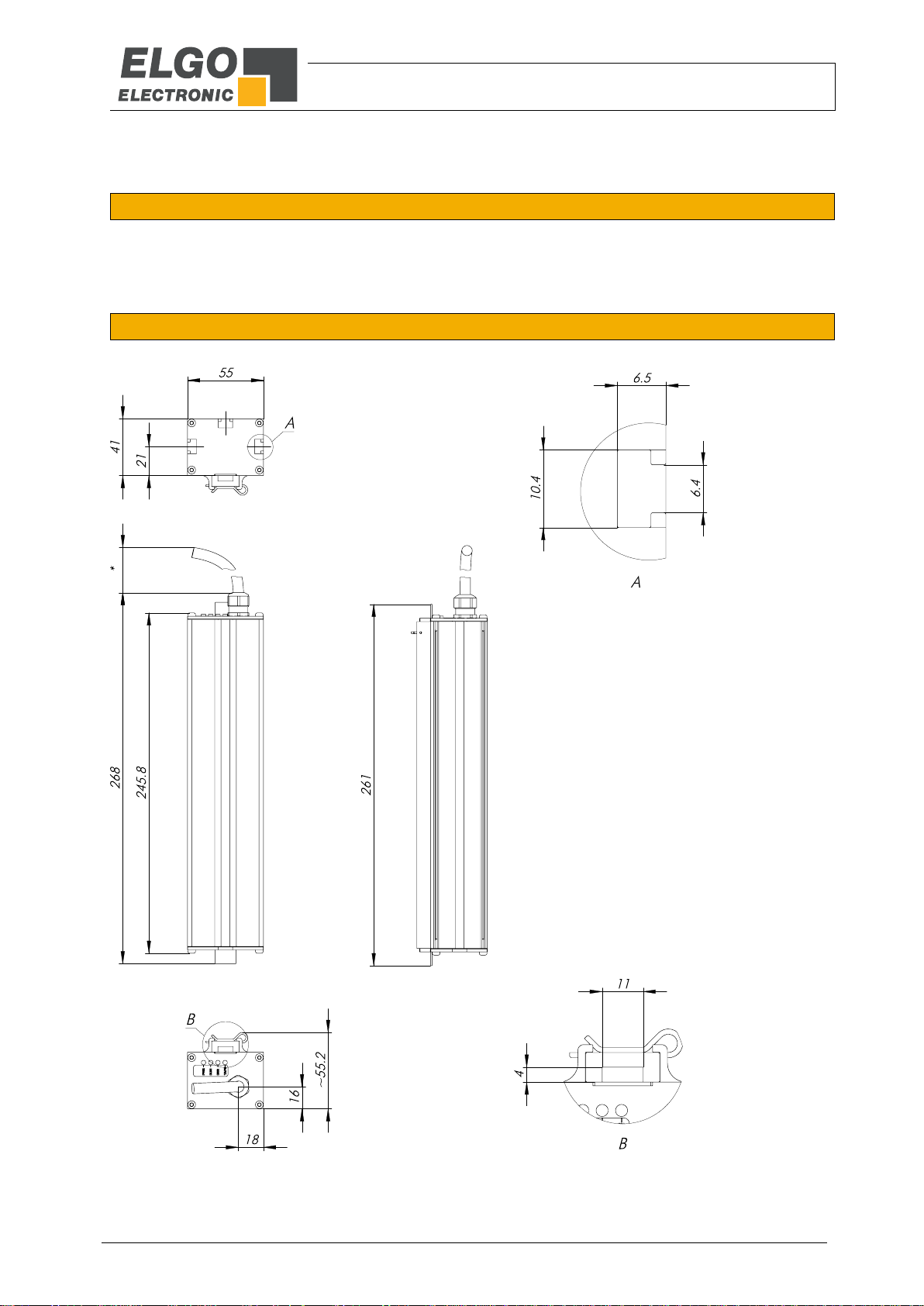
4.2 Dimensions Sensor Standard
Figure 1: Dimensions Sensor Standard

Technical Data
- 9 -
244
236
40
55
55
51
271
55
51
32,5
41,5
13,5
38
19,5
4.3 Dimensions Sensor Option unguided
Figure 2: Dimensions Sensor Option unguided
4.4 Dimensions Sensor Option PNO
Figure 3: Dimensions Sensor Option PNO

Technical Data
- 10 -
LIMAX02 (Standard version)
Mechanical Data
Measuring principle
absolute
Repeat accuracy
+/- 1 Increment
System accuracy in µm at 20°C
+/- (1000 + 50 x L[m])
L = measuring length in meter
Distance from sensor to magnetic
tape
4 mm
Basic pole pitch
8 mm
Sensor housing material
aluminium
Sensor housing dimensions
L x W x H = 246 x 55 x 55 mm
Necessary type
AB20-80-10-1-R-D-15-BK80
Maximum measuring length
260 m
Connection
Open cable ends (more options 8)
Sensor cable
3 m standard cable length (other on request)
Weight
approx. 460 g without cable (cable approx. 60 g/m)
Electrical Data
Supply voltage
10 … 30 VDC
Residual ripple
10 … 30 VDC < 10%
Power input
max. 200 mA
Interfaces
SSI, CAN, CANopen (DS406, DS417), RS422, RS232, RS485, PROFIBUS
Resolution
According to the Type Designation ( 8)
Speed
max. 10 m/s (higher speeds on request)
Conditions
Storage temperature
-20 … +85° C
Operation temperature
-10 … +70° C
(-25 … +85° C on request)
Humidity
max. 95 %, not condensing
Protection class
IP50
Scale 5:1
4.5 Dimensions Magnetic Tape
Figure 4: Dimensions Magnetic Tape
4.6 Technical Data Sensor

Technical Data
- 11 -
TEMPLATE Magnetic Tape AB20-80-10-1-R-D-15-BK80
Coding
absolute, single track system
Pole pitch
8 mm
Operation temperature installed
-20 … +65° C
(-20 … +80° C when using without adhesive tape, options „B“ or „D“)
Storage temperature uninstalled
Short-term: -10 … +60° C
Medium-term: 0 … +40° C
Long-term: +18° C
(-20 … +80° C when using without adhesive tape, options „B“ or „D“)
Gluing temperature:
+18 … +30° C
Relative humidity
max. 95 %, non-condensing
Accurateness 20°C in µm
+/- (1000 + 50 x L[m])
(L = measuring length in meters)
Material carrier tape
Precision strip 1.4310 / X10CrNi 18-8 (EN 10088-3)
Double-faced adhesive tape
3M-9088 (observe instructions), others on request
Dimensions
without adhesive tape:
10 mm (+/- 0.1) x 1,35 mm (+/- 0.11)
with adhesive tape (excl. carrier):
10 mm (+/- 0.1) x 1,56 mm (+/- 0.13)
with adhesive tape (incl. carrier):
10 mm (+/- 0.1) x 1,63 mm (+/- 0.14)
Length expansion coefficient
16 x 10-6 1/K
Thermal length expansion
∆L[m] = L[m] x [1/K] x ∆[K]
(L = tape length in meters, ∆ = relative temperature change)
Available lengths
up to 260 m
Weight magnetic tape
ca. 62 g/m (incl. magnetic tape and cover tape)
Tape imprint
ELGO standard, printing color black, digit height >= 5 mm
Influence of external magnets
External magnetic fields must not exceed 64 mT (640 Oe; 52 kA/m) on
the surface of the magnetic tape as this could damage or destroy the
code on the tape.
Protection class
IP65
4.7 Technical Data Magnetic Tape
The magnetic tape consists of two components:
The actual magnetic tape which carries the position information
A mechanical stainless steel back iron
Installation and First Start-Up
- 12 -
CAUTION
Please read the operating manual carefully before using the device! Strictly observe the Installation instructions!
In case of damage caused by failure to observe this operating manual, the warranty expires.
ELGO is not liable for any secondary damage and for damage to persons, property or assets.
Der Betreiber ist dazu verpflichtet, geeignete sicherheitsrelevante Maßnahmen zu ergreifen
und durchzuführen.
The operator is obliged to take appropriate safety measures. The first start-up may only be
performed by staff that has been trained and authorized by the operator.
WARNING!
Do not use the device in explosive or corrosive environments!
The device must not be installed close to sources of strong inductive or capacitive interference
or strong electrostatic fields!
CAUTION!
The electrical connections must be made by suitably qualified personnel in accordance with
local regulations.
The device may be designed for switchboard mounting. During work on the switchboard, all
components must be de-energized if there is a danger of touching the energized parts!
(protection against contacts)
Wiring works may only be performed in the de-energized state!
Thin cable strands have to be equipped with end sleeves!
Before switching on the device, connections and plug connectors have to be checked!
The device must be mounted in a way that it is protected against harmful environmental influences such as splashing water, solvents, vibration, shock and severe pollution and the operating temperature must not be exceeded.
5 Installation and First Start-Up
5.1 Operating Area

Installation and First Start-Up
- 13 -
Figure 5: Installation with tension weight
Figure 6: Installation with dowel and spring
Sensor
Magnetic tape
Guide rail
Upper tape fixation
Tension weight
Sway guard
Upper tape fixation
Sensor
Magnetic tape
Spring
Guide rail
5.2 Description installation of the Sensor
5.2.1 Installation Principe
LIMAX02 can be installed at any position in the shaft, depending on spatial conditions and layout of the particular elevator installation.
The magnetic tape is installed freely suspended in the shaft. It can be fixed with the RMS mounting kit (available
as option) on the guide rail. Alternatively fixation in the shaft head is either on beams or directly bolted into the
ceiling. The necessary tension in the tape is provided by a tension weight of about 5 kg. A sway guard at the
bottom will keep the tape from swaying in an uncontrolled position. Alternatively the magnetic tape can be tensioned by a spring.
The sensor head can be mounted onto the cabin or cabin frame, depending on the spatial conditions of the
elevator.

Installation and First Start-Up
- 14 -
The integrated mounting notches on the housing of
the sensor head allow for a very simple and selfexplanatory installation from three sides. You can
either use M6 hexagon head screws (DIN 933) or M6
square nuts (DIN 562), to mount the system at the
desired position.
Figure 7: Mounting grooves on the sensor
NOTE
During installation of the magnetic tape in the sensor, pay attention to the marks on the magnetic tape and on the sensor head.
Wrong orientation of tape vs. Sensor head will yield incorrect position readings!
The arrows printed on the magnetic tape and sensor head point in positive counting direction
(in the direction of the shaft head)!
NOTE External Magnetic Fields
The magnetic tape must not be influenced by external magnetic fields!
The magnetic tape must not come into direct contact with other magnetic fields (e.g. permanent magnets, magnetic clamps, electromagnets, magnetic stands)! This may cause
irreparable damage, which will compromise the measuring accuracy or even the functioning.
5.2.2 Installation of the Sensor
The sensor is fixated on the cabin or on the car frame. The mounting position is basically determined by the
condition.
5.3 Description installation / Mounting of the Magnetic Tape
5.3.1 General Information
The technology has proven to be highly robust.LIMAX02 will work under the most adverse environmental conditions. Extreme temperatures, high moisture and excessive soiling will not alter the information coded onto the
tape nor will these conditions affect reading precision of the sensor. Even weak magnetic fields such as they are
generated by door magnets can be tolerated.
If some basic rules and guidelines are followed LIMAX02 systems require a minimum amount of installation and
maintenance effort while offering maximum lifetime.
One important issue to consider is the protection of the magnet tape against mechanical wear. The LIMAX02
tape consists of two components:
- The magnetic tape which actually carries the position information
- A protective steel tape which gives the mechanical properties

Installation and First Start-Up
- 15 -
NOTE!
The magnetic tape itself is not designed to withstand excessive mechanical wear. It is therefore important to ensure that the system is installed such that the mechanical contact between
tape and sensor head is mainly between the steel tape and the polymer sensor guide. These
two materials have been specifically paired for this application.
Wrong Tolerable
Recommended
Constant contact
between magnetized side
and sensor housing lead
to abrasion
Vertical alignment
minimal contact between
band and sensor
Enforced contact
between steel band
and polymer housing
Tape touches
the guide with
the magnetized
side
Tape touches
the guide with
the steel side
5.3.2 Installation Concept
5.3.2.1 Basic Principle for the Mounting
Avoiding contact between the magnetic side and the sensor could be achieved with a perfectly perpendicular
installation of the band. Yet, in reality this is not practicable. It is therefore preferable to install the tape with a
horizontal offset from the sensor. During operation this method will result in a forced contact between the steel
side of the band and the polymer guide of the sensor which guarantees an optimal operation of the system.
Figure 8: Assessment of the pretention of the magnetic tape

Installation and First Start-Up
- 16 -
Shaft head Shaft pit
Magnetic Tape
Sensor
Mounting Angle
Car
5.3.3 Installation Procedure
1. Attach the top end of the tape in the shaft head. Ideally use an ELGO Mounting Kit. Check for correct
orientation of the tape. The arrows on the magnetic side must point in upward direction.
Figure 9: Correct orientation of the magnetic tape
2. The magnetic side of the tape must face the sensor body. In most situations this means that the steel side
points to the shaft wall.
3. Drive down the shaft with inspection speed and unroll the tape. The ELGO tape packaging system has
been specifically designed for this purpose. The tape can be unwound directly from the box without opening.
4. Attach the tension weight (about 7.5 kg) at the bottom end of the tape in the shaft. Secure the tape with a
sway guard. Pay attention to a proper vertical mounting of the tape.
If you use dowels to fix the tape in the shaft, tighten the spring such, that the according tractions results to
minimum 7.5 kg. When using the ELGO Mounting Kit RMS/RMS90 this is equivalent to a spring elongation of about 90 mm.
Note that slightly higher tensile forces are never a problem, but avoid under-tensioning. In higher buildings it may even be preferable to slightly increase the tension in order to prevent flapping of the tape during operation. However, if correctly installed tensile forces of more than 10 kg should never be necessary.
5. Drive the car to the middle of the shaft.
6. Attach the sensor to the car. The side with the cable outlet and the LED’s must face upward.
7. Adjust the sensor using the tape as a reference. First, align sensor and magnet band on their centerline.
Figure 10: Distance and orientation of the magnetic tape in relation to the sensor

Installation and First Start-Up
- 17 -
Tape is flat in
the guide
Tape is
skewed in the
guide
Tape is
skewed in the
guide
Tape is flat in
the guide
Tape is
skewed in the
guide
Tape is
skewed in the
guide
8. Adjust now the distance between sensor and tape. Up to a travel height of 50 m we recommend an offset
of at least 15 mm. This will ensure steady contact between steel side of the band and the polymer guide
of the sensor. This level can be increased later, if it turns out that the band still rubbing with the magnetic
side on the sensor.
In higher installations this distance may be increased by the initial assembly up to 5 cm.
Pay attention to a perpendicular alignment of the sensor. Misalignment will lead to increased wear.
9. Pass the tape through the sensor. Loosen the splint-pin and release the polymer guide. Insert the tape and
re-attach the guide with the tape in its position.
10. Pay attention that the pad does not slip after removal of the polymer guide from the aluminum guide out
and drops down in the shaft.
11. Check for proper alignment of band vs. sensor. Any angular offset should be corrected.
Figure 11: Assessment of the guiding rail of the tape in the sensor - twisted magnetic tape
Figure 12: Assessment of the guiding rail of the tape in the sensor - skewed mounting of the magnetic tape

Installation and First Start-Up
- 18 -
Recommended
Falsche vertikale
Ausrichtung
12. IMPORTANT: Installation check!
Values for tape tension and offset between tape and sensor are guidelines based on experience. But in
any case, a proper check after installation is mandatory. It must absolutely be avoided that the magnetic
side constantly grinds on the sensor body during operation. Run an inspection trip along the complete
shaft. Observe the system and pay attention to the respective positions of band and sensor. You have
achieved an optimal installation if the steel side of the tape is constantly pressed slightly against the polymer guide of the sensor. At some points in the shaft also double-check on the bottom side of the sensor.
If the sensor is tilted it may look good on top but the tape can still grind along the bottom edge of the
sensor.
Figure 13: Assessment of the vertical alignment of the sensor
13. If the installation check reveals that the tape slides on magnetic side, start to increase the offset between
sensor and tape. Values of up to 5 cm are acceptable. If this measure does not solve the problem it is
very likely that the tape is not plumb in the shaft. This is easy to check for, provided your elevator control
allows for inspection trips without the absolute position signal: Just take the tape out of the sensor and
run an inspection trip along the shaft. Observe the distance between sensor and tape along the travel.
Misalignments will become obvious.
Also ensure that the tension on the tape is sufficient. A loosely tensioned tape will hinder proper guiding.
14. After completion of the installation clean the tape. Beginning at the top of the shaft drive down the com-
plete travel distance pulling the magnet tape through a dry cloth.
Be specifically alert if steel construction work is taking place in the shaft. Steel particles released by grinding, welding, or such work will adhere to the magnetic tape. Clean this debris off instantly.
Repeat the cleaning process before putting the elevator into service after complete installation.

Connections and Interfaces
- 19 -
CAN Standard
Bitrate
250 kbit/s
Resolution
1.0 mm
Identifier
184 (hex)
First 4 Bytes
Position in mm
Next 2 Bytes
Speed in mm/s
6 Connections and Interfaces
6.1 LED’s (Operating status and notices)
The LED’s located on the front serve for monitoring of operating conditions.
With startup it has to be ensured that the yellow LED illuminates as this monitors the internal supply voltage.
Figure 14: LED signals on the upper side of the sensor
PWR YELLOW Supply voltage
ON = Supply voltage OK
OFF = Supply voltage not provided
RUN GREEN
for CANopen device: RUN-LED according to DR 303-3
other device: Interface state, flashes during active communication
ERR RED
for CANopen device: ERR-LED according to DR303-3
other device: Error message
ON = State error, system not operational
OFF = State OK, system ready for operation
TAPE YELLOW Indicator for magnet tape
ON = Magnet tape missing
OFF = Magnet tape available
6.2 CAN Interface
6.2.1 CAN Standard
Table 1: Configuration of CAN Standard

Connections and Interfaces
- 20 -
CANopen DS406
Bit rate
250 kbit/s
Identifier
184 (hex)
Event timer
10 ms
Producer heartbeat
500 ms
Resolution
1.0 mm
First 4 Bytes
Position in mm
Next 2 Bytes
Speed in mm/s
CANopen DS417
Bit rate
250 kbit/s
Identifier
18 C (hex) [Node ID 0x04]
Event timer
0 (switched off)
Producer heartbeat
500 ms
Resolution
0.5 mm
ABS-Position
Speed
xxh
MSB
yyh
LSB
yyh
MSB
xxh
xxh
LSB
xxh
ABS-Position
Speed
xxh
MSB
yyh
LSB
yyh
MSB
xxh xxh
LSB
xxh
ABS-Position
xxh
MSB
xxh xxh
LSB
xxh
Figure 15: Protocol CAN standard
6.2.2 CANopen DS 406 and DS417
For LIMAX02 the CANopen Interfaces DS406 (encoder profile) und DS417 (lift profile) are available. These
interfaces are configured by default as follows:
Table 2: Configuration of CANopen DS406
Figure 16: Protocol DS406
Table 3: Configuration of CANopen DS417
Figure 17: Protocol DS417

Connections and Interfaces
- 21 -
9-pin D-SUB connector
Open cable exit
PIN-No.
Function
Color
Function
Pin 6
0 V / GND
White
0 V / GND
Pin 9
+ 24 VDC
Brown
+ 24 VDC
Pin 2
CAN L
Green
CAN L
Pin 7
CAN H
Yellow
CAN H
Pin 3
CAN GND
Blue
CAN GND
Housing*
PE
Shield*
PE
Note!
The commands which are described in section 6.2.4.2 Normal Mode are only processed by
the CANopen device in the Operational and Pre-Operational mode.
2B 17 10 00 YY ZZ 00 00
DLC:ID: XXX 8
Set Heartbeat cycle time
Master
CANopen
device
XXX = 600h + node-ID
Example: 604h for the device node-ID 4
YY = LSB of cycle time in milliseconds
ZZ = MSB of cycle time in milliseconds
Example: for a cycle time of 500ms (1F4h) is
YY = F4h and ZZ = 01h
ID: DLC:XXX 8
60 17 10 00 00 00 00 00
XXX = 580h + node-ID
Example: 584h for the device node-ID 4
Acknowledgment of the CANopen device
6.2.3 Pin Assignment CAN
Table 4: Pin Assignment CAN
6.2.4 Command Descriptions
6.2.4.1 Initial Operation
*) please connect shield only at control unit side!
After starting the CANopen device is in the Pre-operational Mode ( 6.2.6.2) and therefore doesn’t send any
position data. In order to achieve this, the device needs to be set into Operational Mode ( 6.2.6.1) and if
necessary the sending cycle of the position data has to be adjusted ( 6.2.4.4).
6.2.4.2 Normal Mode
6.2.4.3 Setting the Heartbeat Cycle Duration
A CANopen device sends the heartbeat cyclically. This message communicates the current Operating Mode to
the other bus sharing units.
1. Change into the Operational or Pre-operational Mode, if necessary
2. The following illustration shows the CAN-message, which should be transmitted to the CANopen device
and the following answer.
Figure 18: Setting the Heartbeat Cycle Duration

Connections and Interfaces
- 22 -
2B UU VV 05 YY ZZ 00 00
DLC:ID: XXX 8
Set cycle time for position data
Master
CANopen
device
XXX = 600h + node-ID
Example.: 604h for the device with node-ID 4
UU = 00h (DS406), 06h(DS417)
VV = 18h (DS406), 19h(DS417)
YY = LSB of cycle time in milliseconds
ZZ = MSB of cycle time in milliseconds
Example: for a cycle time of 10ms (Ah) is
YY = 0Ah and ZZ = 00h
05
ID: DLC:XXX 8
60 UU VV 00 00 00 00
XXX = 580h + node-ID
Example: 584h for the device node-ID 4
Acknowledgment of the CANopen device
3. If the setting should be maintained in the case of a power failure, the changes have to be saved, as
described in section ( 6.2.5).
6.2.4.4 Setting the Sending Cycle for the Position Data
The position data are sent cyclically by the device, therefore the device has to be in the Operational Mode (
6.2.6.1).
The settings of the cycle duration takes place in the device profile DS406 in the object 1800h, Sub-index 5 and
for devices with DS417 profile in object 1906h, Sub-index 5.
1. Change into the Operational or Pre-operational Mode, if necessary.
2. The following figure shows the CAN-message, which should be transmitted to the CANopen device and
the following answer.
Figure 19: Setting the Sending Cycle for the position data
3. If the settings should be maintained in case of a power failure, the changes have to be saved, as de-
scribed in section ( 6.2.5).
6.2.5 Saving the Parameters
In the normal case the settings are lost at power failure. In order to avoid this, they need to be saved according
to the following procedure.
1. Change into the Operational or Pre-operational Mode, if necessary.
2. The following figure shows the CAN-message, which should be transmitted to the CANopen device and
the following answer:

Connections and Interfaces
- 23 -
23 10 10 01 73 61 76 65
DLC:ID: XXX 8
Saving all parameters
Master
CANopen
device
XXX = 600h + node-ID
Example: 604h for the device node-ID 4
ID: DLC:XXX 8
60 10 10 01 00 00 00 00
XXX = 580h + node-ID
Example: 584h for the device with node-ID 4
Acknowledgment of the CANopen device
01 00
DLC:ID: 000 2
Changing all participants into the Operational Mode
Master
CANopen
device
80 00
DLC:ID: 000 2
Changing all participants into Pre-Operational Mode
Master
CANopen
device
Figure 20: Saving the parameters
6.2.6 Changing the Operating Modes
6.2.6.1 Changing the device into the Operational Mode
In the Operational Mode the communication of the device is fully functional.
The following CAN-message causes the change of all CANopen participants into the Operational Mode.
Figure 21: Changing the device into the Operational Mode
6.2.6.2 Changing the device into the Pre-operational Mode
In the Pre-operational Mode the communicating settings of the device are adjusted.
The following CAN-message causes the change of all CANopen participants into the Pre-Operational mode.
Figure 22: Changing the device into the Pre-operational Mode

Connections and Interfaces
- 24 -
02 00
DLC:ID: 000 2
Changing all participants into Stopped Mode
Master
CANopen
device
ATTENTION!
With the following command all the bus sharing units which are in the Stopped Mode are
changed into the LSS Configuration Mode. Use this command, if only one device is connected
to the bus, because other devices could be affected in their function.
04 01 00 00 00 00 00 00
DLC:ID: 7E5 8
Changing all participants into LSS Configuration Mode
Master
CANopen
device
Saving the parameters
17 00 00 00 00 00 00 00
DLC:ID: 7E5 8
ID: DLC:7E4 8
17 00 00 00 00 00 00 00
Master
CANopen
device
6.2.6.3 Changing the device into the Stopped Mode
Bus sharing units in the Stopped Mode are passive participants. In this mode all the communication is turned off,
except the monitoring activity (e.g. heartbeat).
The following CAN-message causes the change of all CANopen participants into the Stopped Mode:
Figure 23: Changing the device into the Stopped Mode
6.2.7 LSS Configuration
Basic settings like node-ID and baud rate have to be adjusted with the Layer Setting Services (LSS).
6.2.7.1 Changing into the LSS Configuration Mode
In order to be able to change the Parameter (node-ID, bit rate), the device has to be changed into the LSS Configuration Mode.
The following CAN-message causes the change into the LSS Configuration Mode.
Figure 24: Changing into the LSS Configuration
6.2.7.2 Saving the Parameters in the LSS Mode
In order not to lose the changes in case of a power failure, they have to be saved in the non-volatile memory of
the CANopen device.
The following figure shows the necessary message for this procedure.
Figure 25: Saving the parameters in the LSS Mode

Connections and Interfaces
- 25 -
ATTENTION!
During the saving procedure the device is not accessible over a period of a few milliseconds.
13 00 XX 00 00 00 00 00
DLC:ID: 7E5 8
ID: DLC:7E4 8
13 00 00 00 00 00 00 00
Master
CANopen
device
Adjusting the baud rate
Values for XX:
0 = 1 MBit/s
1 = 800 kBit/s
2 = 500 kBit/s
3 = 250 kBit/s
4 = 125 kBit/s
5 = reserved
6 = 50 kBit/s
7 = 20 kBit/s
8 = 10 kBit/s
Changing the node-ID
11 XX 00 00 00 00 00 00
DLC:ID: 7E5 8
ID: DLC:7E4 8
11 00 00 00 00 00 00 00
CANopen
device
Master
XX = new node-ID in the range 01h .. 7Fh
6.2.8 Setting the Baud Rate
1. Change the device into the Stopped mode ( 6.2.6.3)
2. Change the device into the LSS Configuration Mode ( 6.2.7.1)
3. Change baud rate according to the following command:
Figure 26: Setting the baud rate
4. Save parameter as described in section ( 6.2.7.2).
5. Turn the device off and restart it again.
6.2.9 Setting the node-ID
1. Change the device into the Stopped Mode ( 6.2.6.3)
2. Change the device into the LSS Configuration Mode ( 6.2.7.1)
3. Change node-ID with the following message:
Figure 27: Setting the node-ID
4. Save parameter as described in section ( 6.2.7.2).
5. Turn the device off and restart it again.

Connections and Interfaces
- 26 -
Open cable ends
Color
Function
White
0 V / GND
Brown
+ 24 VDC
Pink
Data -
Grey
Data +
Yellow
CLK -
Green
CLK +
Shield
PE
9-pin. D-SUB Connector
NEWLIFT FST1 (D9M0)
NEWLIFT FST2 (D9M1)
Pin
Function
Function
1
DATA +
0V / GND
2
CLK -
CLK +
3 - N.C.
4
24 VDC
DATA +
5
0V / GND
0V / GND
6
DATA -
+ 24 VDC
7
CLK +
CLK -
8 - DATA -
Housing
PE
N.C.
T
23
22
21
20
19
18
17
16
15
14
13
12
11
10 9 8 7 6 5 4 3 2 1 0
PFB = Power Failure Bit
Tm = monostable multivibrator time > 10µs
24 Data bits/3 Bytes
PFB
6.3 SSI Interface
6.3.1 Function Principle
If the clock is not interrupted for the time Tm-T/2 (output of further 25 periods), the shift register clocks once
again the same data value (error recognition in the evaluation). Some encoders contain a Power Failure Bit
(PFB). Attention: With the LIMAX02 the PFB is always “LOW”!
6.3.2 Data Protocol
T = length of clock signal
Figure 28: Data Protocol SSI Interface
6.3.3 Pin Assignment
Table 5: Pin Assignment SSI open cabel ends
Table 6: Pin Assignment SSI Interface

Connections and Interfaces
- 27 -
ABS position
STX
02h
MSB
xxh
00h
ETX
03h
LSB
xxh
xxh 0Dh
Open cable ends (Standard)
Color
RS232
RS422
RS485
White
0 V / GND
0 V / GND
0 V / GND
Brown
+ 24 VDC
+ 24 VDC
+ 24 VDC
Pink
TX
TX -
TX -
Grey
RX
TX +
TX +
Yellow
-
RX - Green
-
RX +
Shield
PE
PE
PE
ABS position
Speed
STX
02h
MSB
xxh
00h
ETX
03h
LSB
yyh
MSB
yyh
LSB
xxh
xxh 0Dh
STX = starts a message
ETX = ends a message
STX = starts a message
ETX = ends a message
Figure 29: Data Protocol Version 2321 / 4221 / 4851
Figure 30: Data Protocol Version 2320 / 4220 / 4850
6.4 RS232 / RS422 / RS485*
*) Attention: RS485 only unidirectional
If the measuring system is equipped with an RS232, RS485 or RS422 interface, the data communication has the
following format:
19200 baud (other baud rates on request)
1 Start bit
8 data bits
1 stop bit
no parity
6.4.1 Data Protocol
The measured absolute position will be represented in the three ABS-position data bytes.
Version 2321 / 4221 / 4851
Version 2320 / 4220 / 4850
6.4.2 Pin Assignment
Table 7: Pin Assignment

Connections and Interfaces
- 28 -
06h = characterizes a message as address allocation
i = the new LIMAX02 address. Important: At the answer you get the new address + 80h.
04h = characterises the message as position request
i = address of the LIMAX02 (0Bh – 7Fh) to request
Bit 0 has the value 10µm, position values are always smaller than FFFF00h
STX = starts a message
ETX = ends a message
Check Byte = contains the arithmetic checksum of STX, byte 1 and byte 2.
The meaning of bytes 1 to 4 can be found in the following chapters.
ABS-Position
05h = characterizes a message as address request
i = LIMAX02 address
FFh FFh does not occur immediately after STX with position inquires as answer!
In this case (0Bh <= i <= 7Fh) this is the answer of the address request.
STX
02h
Byte 1 ETX
03h
Byte
check
Byte 2 STX
02h
Byte 1 Byte 4 Byte 3 Byte 2 STX
02h 04h
ETX
03h
Byte
check i
STX
02h
MSB
xxh
Adr. i LSB
xxh xxh
STX
02h 05h
ETX
03h
Byte
check 05h
STX
02h FFh
ETX
03h i xxh FFh
STX
02h
06h
ETX
03h
Byte
check
i
STX
02h FFh
ETX
03h
i +
80h FFh
6.4.3 Command Descriptions
Important:
Before you send a new message to the LIMAX02 wait for the answer first. After allocating a new address the
LIMAX02 answers in max. 0.5 seconds. In other cases it even in a few milliseconds. After this time it is not
expected to get an answer (transmission error).
6.4.3.1 Principle Format of Message
To LIMAX02 answer
6.4.3.2 Position request of LIMAX02 with the address “i”
To LIMAX02 answer
6.4.3.3 A LIMAX02 address request
Attach in each case only one LIMAX02 e.g. over a RS422/RS232 converter to the serial interface (COM-port) of
a PC.
To LIMAX02 answer
6.4.3.4 Allocation of an LIMAX02 address
Attach in each case only one LIMAX02 e.g. over a RS422/RS232 converter to the serial interface (COM-port) of
a PC.
To LIMAX02 answer
The addresses 80 h – FFh as well as 00 h – 0 Ah are FORBUDDEN. If you try to assign an address smaller than
eight, LIMAX02 gives you a “negative answer” and keeps its former address.

Connections and Interfaces
- 29 -
Code
Meaning
04h
Wrong sequence of bytes sent to LIMAX02, for example if 4. Byte after STX is no ETX or the Byte after
STX is not 0x04, 0x05 or 0x06.
05h
Receiving Error / Interface Error (for example if a message with a wrong baud rate was sent etc.)
06h
Invalid LIMAX02 address: appears after trying to assign an address smaller 0Bh or bigger 7Fh to LIMAX02.
07h
LIMAX02 has lost its address: internal check of X redundantly stored address of LIMAX02 has failed.
This message is sent at power up immediately if an error in reading EEPROM is detected or if the internal address error cannot be fixed.
08h
Internal EEPROM storage error.
09h
Error in transmission of position (no tape, tape damaged or distance between tape and sensor head
too big).
0Ah
Check-Sum-Error: Check-sum of a message sent to LIMAX02 is wrong.
ERR = Error-Code (04h – 0Ah) error – codes are listed at the next page.
STX
02h
FFh
ETX
03h
ERR
xxh
FFh
6.4.3.5 Error Messages
If one of the described operations failed for some reason LIMAX02 gives an error message with a respective
error-code.
Answer from LIMAX02
Table 8: Error-codes of an addressable LIMAX02

Connections and Interfaces
- 30 -
6.4.3.6 Connection to a RS422 Master
Figure 31: Connection to a RS422 Master
6.5 Option Unguided
LIMAX02 "unguided" is an absolute measuring system, which is used for positioning in the most diverse areas
horizontally and vertically. It consists of only two components: magnetic tape and the sensor.
Figure 32: LIMAX02 Option unguided

Connections and Interfaces
- 31 -
Function
Setting Range
Factory Setting
Monoflop
20 ... 255 µs
[200]
Clock quantity SSI
18 ... 32
[24]
Scale SSI/x
1 ... 255
[1]
Offset
-1073741823 ... 1073741824
[0]
LED
RUN (green)
ERROR (red)
MSD LSD
6.6 Option PROFIBUS Interface
6.6.1 LED’s (Operation Status and Messages)
The LED’s located on the top side, a green LED (Bus Run) and a red LED (Bus Fail), serve for monitoring of op-
erating status. For setting the address are two rotary coding switches located on the top next to the LED’s
BUS RUN GREEN
ON = Ready
OFF = Supply voltage not provided
Flashes cyclic = Slave has no cyclic data exchange with PROFIBUS-DP-MASTER
Flashes irregular = start: Missing or faulty configuration
Runtime: Host watchdog- time error
BUS FAIL RED
ON = unrecoverable Converter – Fault
OFF = no error / bus in cycle
Flashing = Converter not addressed by the master
6.6.2 Adjustment
6.6.2.1 Address Adjustment
The address adjustment is carried out with the coding switches on top of the housing. The higher decade with
the coding switch MSD and the low decade with the coding switch LSD.
Figure 33: Address Adjustment and LED Signaling
6.6.2.2 Parameter Adjustment
The following parameters can be adjusted by GSD File.
(GSD File is on CD-ROM delivered
Table 9: Parameter Adjustment by GSD File

Connections and Interfaces
- 32 -
PROFIBUS Interfac
Transmission
RS485 two-wire line
Wire lenght
1200 m at 9,6 kBaud
200 m at 1,5 Mbaud
100 m at 12 MBaud
Baud rate
9,6 kBaud to 12 Mbaud (auto detect)
Clock rate max.
250 kHz
Participants
max. 32 per Segment (with repeater until 126 expandable)
Mono- and Multi-master systems are possible
In delivery status is participant 05 set
Table 11: Pin Assignment PROFIBUS IN
Table 12: Pin Assignment PROFIBUS OUT
PROFIBUS IN (Flanged Plug M12)
Pin
Function
1
N.C.
2
Data A
3
N.C.
4
Data B
5
Shield
PROFIBUS OUT (Flanged Socket M12)
Pin
Function
1
N.C.
2
Data A
3
N.C.
4
Data B
5
Shield
Power supply (Fanged Plug M8)
Pin
Color
Function
1
Brown
+ 10 to 30 VDC
2
White
N.C.
3
Blue
0 V / GND
4
Black
N.C.
6.6.2.3 PROFIBUS Interface
The sensor option profibus is fitted as standard with a profibus interface according to IEC61158 / IEC61784.
The following parameters are specified.
Table 10: Parameter PROFIBUS Interface
6.6.2.4 Pin Assignment
Table 13: Power Supply

Connections and Interfaces
- 33 -
Profibus INProfibus OUT
Power Supply
Figure 34: Pin Assignment PROFIBUS

Disturbances, Maintenance, Cleaning
- 34 -
CAUTION!
The device, the connection line and the signal cable must not be installed next to sources of interference that emit
strong inductive or capacitive interference or strong electrostatic fields.
External perturbations can be avoided thorough suitable cable routing.
The screen of the signal output cable should only be connected to the following circuit on one side. The screens
should not be grounded on both sides. Signal cables always have to be routed separately from the load power line.
A safety distance of at least 0,5 m has to be kept from inductive and capacitive sources of interference such as contactors, relays, motors, switching power supplies, clocked controllers etc!
If interferences occur in spite of all the items stated above being observed, please proceed as follows:
1. Installation of RC-circuits via contactor coils of AC-contactors (e.g. 0,1 µF / 100 Ω)
2. Installation of recovery diodes via DC-inductors
3. Installation of RC-circuits via the different motor phases (in the terminal box of the motor)
4. Do not connect protective earth and ground
5. Connect a mains filter ahead of the external power pack
WARNING!
Danger of injury through non-conventional fault clearance!
Non-conventional fault clearance can lead to severe injuries and damage of property.
Therefore:
Any work to clear the faults may only be performed by sufficiently qualified staff
Arrange enough space before starting the works
Make sure that the mounting area is clean and tidy. Loose components and tools are sources of accidents.
If components need to be replaced:
Pay attention to a correct installation of the spare parts.
Reinstall all the fixing elements properly
Before turning on the device, ensure that all covers and safety equipment is installed correctly and functions
properly
7 Disturbances, Maintenance, Cleaning
This chapter describes possible causes for disturbances and measures for their removal. In case of increased disturbances, please follow the
measures for fault clearance in chapter 7.1.
In case of disturbances that cannot be eliminated by following the advice and the fault clearance measures given here, please contact the
manufacturer (see second page).
7.1 Fault Clearance
7.2 Re-start after Fault Clearance
After the fault clearance:
1. Reset the emergency stop mechanism if necessary
2. Reset the error report at the super-ordinate system if necessary.
3. Ensure that there are no persons in the danger area.
4. Follow the instructions from chapter 5.

Disturbances, Maintenance, Cleaning
- 35 -
WARNING!
Danger through non-conventional maintenance!
Non-conventional maintenance can lead to severe injuries and damage of property.
Therefore:
Maintenance works may only be completed by staff that has been authorized and trained by the operator.
WARNING!
The device can only be cleaned with a damp cloth, do not use aggressive cleanser!
7.3 Maintenance
The LIMAX02 shaft information system requires little maintenance. On the occasion of regular elevator inspection and maintenance do the
following:
Optical inspection of proper alignment between sensor and band. Worn off material indicates possible alignment flaws. Check
for proper guiding of the band along the complete travel distance. Correct if necessary as described in the installation procedure
above.
Optical inspection of the band. Check for abrasions or other mechanical damages. Small mechanical damages (scratches, dents,
or even small chips) do not interfere with the measuring performance at all.
However, a pre-damaged band is more exposed to mechanical stress and is prone to further wear.
Check for proper tension of the band. If the mounting was via a flute, the tension can decrease over time. Readjust if necessary.
Inspect the polymer guide for wear. Clean if dust and dirt have accumulated between polymer guide and sensor case. The poly-
mer guide is a wear part. Replace if necessary.
Clean the band. Use a dry and clean cloth. Begin at the head of the hoistway drive down the complete travel distance pulling the
magnet band through a dry cloth.
7.4 Cleaning

Type Designation
- 36 -
LIMAX2
Series / Type:
LIMAX2 = LIMAX02 (1-Kanal)
Signal cable length:
030 = 3,0 m (Standard)
050 = 5,0 m
Other on request
Resolution:
62N5 = 62,5 µm = 0,0625 mm
0125 = 125 µm = 0,125 mm
0250 = 250 µm = 0,25 mm
0500 = 500 µm = 0,50 mm
1000 = 1000 µm = 1,00 mm
---
SN-number:
00 = standard version
01 = special version
- 1000 CO0T -
Interface:
2320 = RS232 [sta ndard pr otocol, RS232 / positio n]
2321 = RS232 [extended protocol RS232 / po sition & speed]
4220 = RS422 [sta ndard protocol, RS422 / po sition]
4221 = RS422 [extended protocol RS422 / positio n & speed]
4850 = RS485 on request
CN0 = CAN [standard pr otocol, basic-CAN]
CO0 = CANopen [Encoder Profil DS406]
CO1 = CANopen [Elevator Profil DS417]
PNO = Profibus [according to IEC61158/IEC61784, standard ID 5, other on request]
SSB0 = SSI-Interface [25-bit binary code / position]
SSG0 = SSI-Interface [25-bit gray code / Position]
CAUTION:
-> CAN Interface is optional available with galvanic isolation / assem bly CAN-load resistor selectable
-> RS232- Interface is never terminated!
-> RS422- & RS485- & SSI- Interface is basically terminated!
Options:
(Multiple choice possible)
U = option unguided
PNO = 1 pc. Flange plug M8, 1 pc. Flange plug M12 und 1 pc. Flange socket M12
D9M = 9-pol. D-Sub-connector [CAN & CANopen]
D9M1 = 9-pol. D-Sub-connector [SSI / option NEWLIFT FST2]
D9M3 = 9-pol. D-Sub-connector [SSI / option LödigeSEW]
D9F0 = 9-pol. D-Sub-socket [RS232 / to connect to DEE/DTE ]
(open cable end if no option is selected!)
Terminat ed 120R (T)
Not terminated
CN0T (Standard)
CN0
Terminat ed 120R (T)
Not terminated
CO0T (Standard)
CO0
Terminat ed 120R (T)
Not terminated
CO1T
CO1 (Standard)
CN0TG
CN0G
CO0TG
CO0G
CO1TG
CO1G
SSG0 (Standard) SSG0G
SSB0 (Standard) SSB0G
Without galvanic
isolation
With galvanic
isolation (G)
CAN Interface
Without optocoupler at
clock input (terminated
120R)
With optocoupler at clock
input (G) (terminated
120R)
SSI Interface
D9M03000
8 Type Designation
8.1 Type Designation
Figure 35: Type designation

Type Designation
- 37 -
Product key
Control type
LIMAX2-00-030-0500-CO1TG-D9M
Böhnke bp306/bp308 (CANopen CiA 417) - terminated
LIMAX2-00-030-0500-CO1G-D9M
Böhnke bp306/bp308 (CANopen CiA 417) - not terminated
LIMAX2-00-030-62N5-SSG0-D9M1
NEWLift FST2
LIMAX2-00-030-1000-SSB0
KW Aufzugstechnik David 606
LIMAX2-00-030-1000-CO0
LIMAX02 with CANopen encoder profile DS406
LIMAX2-14-030-1000-SSBX
Kollmorgen MRL4 / MFE4 (MPK400)
LIMAX2-04-015-1000-CO1-D9M
Sodimas Quickinstall
LIMAX2-52-030-1000-CO0G
Securelift
8.2 Control specific Sensors
Table 14: Control specific Sensors

Type Designation
- 38 -
Order Designation
Description
Image
AB20-80-10-1-R-D-15-BK80
Magnetic Tape
Installation kit LIMAX MKF
Mounting set for suspended installation with dowel.
Installation kit LIMAX MKB
Mounting set for suspended installation with guiding rails and rail holder.
Installation kit LIMAX RMS
Mounting set for suspended installation with crossbeam for standard layout.
Installation kit LIMAX RMS 90
Mounting set for suspended installation with crossbeam for “Rucksack” layout.
Installation kit LIMAX S-RMS
Mounting set for suspended installation with crossbeam and tape detection.
LIMAX2 MW
Mounting flange for LIMAX02
CD-ROM with GSD File
Supplied with option profibus
Connection cable power supply
PNO
M8 coupling, 4-pin 5 m length
PROFIBUS – signal line
M12 connector, 5-pin, b-coded (assembled at one
end) 5 m length
PROFIBUS – signal line
M12 coupling, 5-pin, b-coded (assembled at one
end) 5 m length
PROFIBUS – signal line
M12 plug / socket (assembled at both ends) 5 m
length
PROFIBUS - Terminator
M12 4-pin, b-coded
8.1 Accessories
Table 15: Accessories

Index
- 39 -
9 Index
Accessories ..................................................... 38
Accident prevention regulations........................... 4
CAN Interface and Protocols ............................. 19
Causes of risk .................................................... 5
Cleaning ................................................... 34, 35
Connections .................................................... 19
Conventional use ............................................... 6
Demounting ...................................................... 5
Device number .................................................. 8
Dimensions Magnetic Tape ............................... 10
Dimensions Sensor ............................................. 8
Dimensions Sensor Option unguided ................... 9
Disposal............................................................ 5
Disturbances ................................................... 34
Explanation of symbols ....................................... 4
Fault clearance ................................................ 34
First start-up .................................................... 12
Identification ..................................................... 8
Installation ...................................................... 12
Installation of the Sensor .................................. 14
Interfaces ........................................................ 19
LED status notice ............................................. 19
Magnetic tape
Structure ..................................................... 11
Maintenance ............................................. 34, 35
Operating area ............................................... 12
Operational safety ............................................. 4
Option Profibus Interface ................................. 31
Order reference ................................................ 8
Packaging material ............................................ 6
Product Features ............................................... 7
Protection against contact ................................ 12
Protective equipment ......................................... 5
RS232 / RS422 / RS485 .................................. 27
Safety ........................................................... 4, 5
Safety instructions .............................................. 4
Safety rules ....................................................... 4
Sensor Technical Data ..................................... 10
SSI Interface .................................................... 26
Start-up .......................................................... 12
Storage ............................................................ 6
Technical Data Magnetic Tape ......................... 11
Transport .......................................................... 6
Transport damage ............................................. 6
Type designation ............................................... 8

- 40 -
Document- No.:
799000350 / Rev. 9
Document- Name :
LIMAX02-00-MA-E_14-19
Subject to change - © 2019
ELGO Electronic GmbH & Co. KG
EL G O E l e c t r o n i c GmbH & Co . K G
Me as u rin g | P os i tio nin g | C o nt r ol
Carl - B enz - S tr. 1 , D-782 39 Ri elasi n gen
Fon:+49 (0) 7731 9339-0, Fax:+49 (0) 7731 28803
Internet: www.elgo.de, Mail: info@elgo.de
 Loading...