


Operating Manual
SERIES HWD15
Battery powered Display Unit with Rotative Encoder (1250 ppr)
Easy mounting and operation
Battery operation (no wirings required)
Wear-free measuring principle
LCD display with signs, special characters
and battery status indicator
„° “-Symbol for angular measurement assignable
Fraction display in inch mode possible
Resolution 0.1 mm or 0.01 mm via parameters
Display inch mode „0.001 Inch“ is possible
Tool offset and incremental measurement function
799000169 / Rev. 0 / 2019-06-07
Translation of the original operating manual

- 2 -
Publisher
ELGO Electronic GmbH & Co. KG
Carl-Benz-Str. 1
D-78239 Rielasingen-Worblingen
Technical Support
+49 (0) 7731 9339 - 0
+49 (0) 7731 2 88 03
info@elgo.de
Document- No.
799000169
Document- Name
HWD15-000-MA-E_23-19
Document- Revision
Rev. 0
Issue Date
2019-06-07
Copyright
© 2019, ELGO Electronic GmbH & Co. KG

Contents
- 3 -
1 Contents
1 Contents ............................................................................................. 3
2 General, Safety, Transport and Storage ........................................... 4
2.1 Information Operating Manual ........................................................................................... 4
2.2 Explanation of Symbols ...................................................................................................... 4
2.3 Terms and abbreviations .................................................................................................... 4
2.4 Statement of Warranties ..................................................................................................... 4
2.5 Demounting and Disposal .................................................................................................. 5
2.6 General Causes of Risk ..................................................................................................... 5
2.7 Personal Protective Equipment ............................................................................................ 5
2.8 Conventional Use ............................................................................................................. 6
2.9 Safety Instructions for Transport, Unpacking and Loading ....................................................... 6
2.10 Handling of Packaging Material .......................................................................................... 6
2.11 Inspection of Transport ...................................................................................................... 6
2.12 Storage ........................................................................................................................... 6
3 Product Features ................................................................................ 7
3.1 Application Examples ........................................................................................................ 7
4 Technical Data ................................................................................... 8
4.1 Identification .................................................................................................................... 8
4.2 Dimensions ...................................................................................................................... 8
4.3 Technical Data ................................................................................................................. 8
5 Power Supply / Battery Change ......................................................... 9
6 Installation and First Start-Up ......................................................... 10
6.1 Operating Area .............................................................................................................. 10
6.2 Mounting on the Shaft ..................................................................................................... 11
6.3 Adaptation to the Spindle Pitch ......................................................................................... 11
6.4 Display Overview ............................................................................................................ 12
6.5 Key Overview ................................................................................................................. 13
6.6 Parameter Level .............................................................................................................. 14
6.7 Parameter List ................................................................................................................. 15
6.8 Initialization Level ............................................................................................................ 16
6.9 Operator Level Functions ................................................................................................. 16
7 Disturbances, Maintenance, Cleaning ............................................. 18
7.1 Fault Clearance .............................................................................................................. 18
7.2 Re-start after Fault Clearance ........................................................................................... 18
7.3 Maintenance .................................................................................................................. 18
7.4 Cleaning ....................................................................................................................... 18
8 Type Designation ............................................................................. 19
9 Index ................................................................................................ 23
General, Safety, Transport and Storage
- 4 -
DANGER!
This symbol in connection with the signal word “Danger” indicates an immediate danger for the life and health of
persons. Failure to heed these instructions can result in serious damage to health and even fatal injury.
WARNING!
This symbol in connection with the word „Warning” means a possibly impending danger for the life and health of
persons. Failure to heed these instructions can result in serious damage to health and even fatal injury.
CAUTION!
This symbol in connection with the signal word “Caution” indicates a possibly dangerous situation. Failure to heed
these instructions can lead to minor injuries or damage of property.
DANGER!
This symbol in connection with the signal word “Danger” indicates an immediate danger for the life and health of
persons due to voltage. Failure to heed these instructions can result in serious damage to health and even fatal
injury. The operations may only be carried out by a professional electrician.
NOTE!
…points out useful tips and recommendations as well as information for an efficient and trouble-free operation.
Abbreviation/ Term
Connection option acc. to type designation
2 General, Safety, Transport and Storage
2.1 Information Operating Manual
This manual contains important information regarding the handling of the device. For your own safety and operational safety, please observe all safety warnings and instructions. Precondition for safe operation is the compliance with the specified safety and handling instructions. Moreover, the existing local accident prevention regulations and the general safety rules at the site of operation have to be observed.
Please read the operating manual carefully before starting to work with the device! It is part of the product and should be kept close to the
device and accessible for the staff at any time. The illustrations in the manual are for better demonstration of the facts. They are not necessarily to scale and can slightly differ from the actual design.
2.2 Explanation of Symbols
Special notes in this manual are characterized by symbols. The notes are introduced by signal words which express the magnitude of danger.
Please follow this advice and act carefully in order to avoid accidents, damage, and injuries.
Warning notes:
Special safety instructions:
Tips and recommendations:
Reference marks:
Marks a reference to another chapter of this manual.
Marks a reference to another chapter of another document.
2.3 Terms and abbreviations
2.4 Statement of Warranties
The producer guarantees the functional capability of the process engineering and the selected parameters.
General, Safety, Transport and Storage
- 5 -
CAUTION!
Wrong disposal causes environmental damages! Electronic scrap, electronic components, lubricants and other
auxiliary materials are subject to special refuse and can only be disposed by authorized specialists!
CAUTION!
Please read the operating manual carefully, before using the device! Observe the installation instructions!
Only start up the device if you have understood the operating manual. The operating company is obliged to take
appropriate safety measure. The initial operation may only be performed by qualified and trained staff.
Selection and installation of the devices as well as their embedding into the controlling system require qualified
knowledge of the applicable laws and normative requirements on the part of the machine manufacturer.
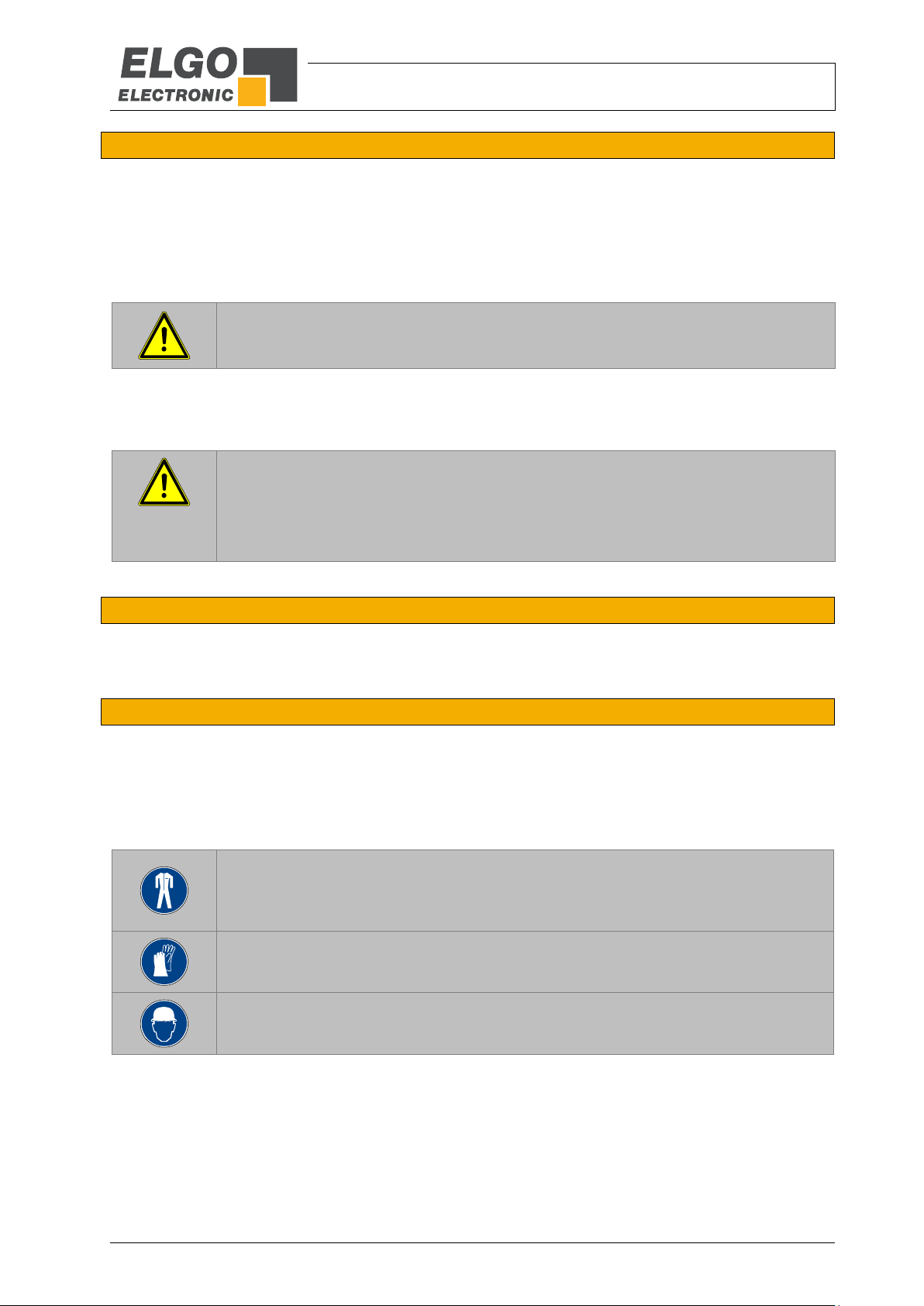
PROTECTIVE CLOTHING
… is close-fitting working clothing with light tear strength, tight sleeves and without distant parts. It serves preliminarily for protection against being gripped by flexible machine parts.
Do not wear rings, necklaces or other jewelry.
PROTECTIVE GLOVES
…for protecting the hands against abrasion, wear and other injury of the skin.
PROTECTIVE HELMET
…for protection against injuries of the head.
2.5 Demounting and Disposal
Unless acceptance and disposal of returned goods are agreed upon, demount the device considering the safety instructions of this manual
and dispose it with respect to the environment.
Before demounting, disconnect the power supply and secure against re-start. Then disconnect the supply lines physically and discharge
remaining energy. Remove operational supplies and other material.
Disposal: Recycle the decomposed elements: Metal components in scrap metal, Electronic components in electronic scrap, Recycle plastic
components, dispose the remaining components according to their material consistence.
Local authorities and waste management facilities provide information about environmentally sound disposal.
Safety
2.6 General Causes of Risk
This chapter gives an overview of all important safety aspects to guarantee an optimal protection of employees and a safe and trouble-free
operation. Non-observance of the instructions mentioned in this operating manual can result in hazardous situations.
2.7 Personal Protective Equipment
Employees have to wear protective clothing during the installation of the device to minimize danger of health.
Therefore:
Change into protective clothing before performing the works and wear them throughout the process.
Additionally observe the labels regarding protective clothing in the operating area.
Protective clothing:
General, Safety, Transport and Storage
- 6 -
CAUTION! Danger through non-conventional use!
Non-intended use and non-observance of this operating manual can lead to dangerous situations.
Therefore:
Only use the device as described
Strictly follow the instructions of this manual
Avoid in particular:
Remodeling, refitting or changing of the construction or single components with the intention to alter the
functionality or scope of the device.
CAUTION!
Transport the package (box, palette etc.) professionally.
Do not throw, hit or fold it.
NOTE!
Claim any damage immediately after recognizing it.
The claims for damage must be filed in the lawful reclaim periods.
2.8 Conventional Use
The ELGO-device is only conceived for the conventional use described in this manual.
The digital handwheel HWD15 only serves to measure distances, angles, revolutions and axis movements.
Claims resulting from damages due to non-conventional use are not possible.
Only the operator is liable for damages caused by non-conventional use.
2.9 Safety Instructions for Transport, Unpacking and Loading
2.10 Handling of Packaging Material
Notes for proper disposal: 2.5
2.11 Inspection of Transport
Check the delivery immediately after the receipt for completeness and transport damage.
In case of externally recognizable transport damages:
Do not accept the delivery or only accept under reserve.
Note the extent of damages on the transportation documents or delivery note.
File complaint immediately.
2.12 Storage
Store the device only under the following conditions:
Do not store outside
Keep dry and dust-free
Do not expose to aggressive media
Protect from direct sun light
Avoid mechanical shocks
Storage temperature (4) needs to be observed
Relative humidity (4) must not be exceeded
Inspect packages regularly if stored for an extensive period of time (>3 months)
Product Features
- 7 -
NOTE!
In the power-off mode the movements or adjustments of the magnetic sensor are not covered!
A referencing has to be performed after the start of operation (at a required mechanical position, the indicator must be set to ZERO or to a defined reference value).
NOTE!
Independent of the setting in P07 (see 6.7), the basic resolution of the HWD15 is
0.01mm). All settings of the multiplication factor refer to this resolution!
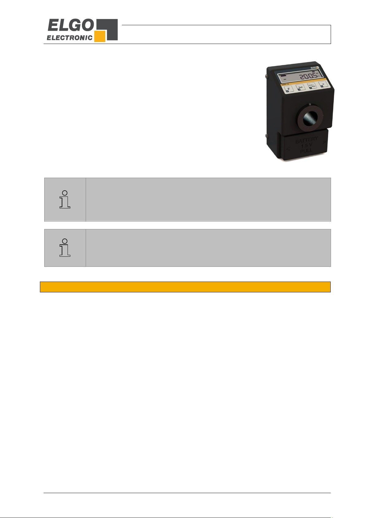
Figure 1: HWD15
3 Product Features
The battery-operated measuring and display system HWD15 provides a hollow shaft (Ø 20 mm) and is directly attached to the spindle. The position is
detected by the integrated sensor and displayed on the LCD display.
Due to its housing with a stable rear wall and flange option including torque
support, the HWD15 is a robust measuring system. However, the mechanical
loads should be absorbed by the spindle. The hollow shaft rotates in a
maintenance-free plain bearing.
The extensive basic functions and parameters allow a wide range of applications. For example, the display can easily be adapted to the respective spindle
pitch (see 6.3). The device provides a common baby cell (good quality). So
the system operates within 12 months of continuous operation.
3.1 Application Examples
Typical applications for the HWD15 are for example:
Manual and motorized adjustment units
Digital measurement of handwheels
Valve adjustments
Wrapping fixtures
Technical Data
- 8 -
Indicator HWD15
LCD
7 digits (height 9 mm) with sign, battery state and measurement units
Measurement units
mm, m, Inch or °
Perspective
12 o’clock
Keyboard
foil with short stroke keys
Measurement principle
quasi absolute
Measurement type
rotative
Battery supply
1,5 V baby cell (Type C / LR14)
Current consumption
< 1 mA at 1.5 V
Batter service life
approx. 12 months (depending on battery type)
Resolution
encoder: 1250 ppr / indicator 0.01 mm (basic resolution)
Operation speed
max. 2.5 m/s
Rotation speed
max. 1500 rpm
Housing dimensions
B x W x D = 72 x 114 x 61.5 mm
Hollow shaft diameter
20 mm
Shaft bearing
plain bearing
Maximum load
axial: 20 N / radial: 200 N
Protection class
IP43
Operating temperature
0 … +50° C
Storage temperature
0 … +70° C
Humidity
max. 80 %, non-condensing
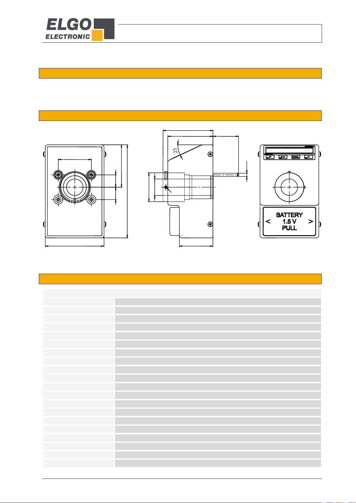
72
114
52
15
40
61.5
30
55
41
35
20
M4
*
M4
15
*) 2 x M4 x 30 screws can be offset or removed
in the hole pattern (internal thread us able)
4 Technical Data
4.1 Identification
The type label serves for the identification of the unit. It is located on the housing of the device and indicates the
exact type designation (=order reference 8) with the corresponding part number. Furthermore, the type label
contains a unique, traceable device number. When corresponding with ELGO please always indicate this data.
4.2 Dimensions
Figure 2: Dimensions
4.3 Technical Data

Power Supply / Battery Change
- 9 -
REMARKS!
For a long operating time, the use of commercially branded batteries is recommended.
When all battery symbols (see also section 6.4) on the LCD display are extinguished,
the battery should be changed as soon as possible.
When changing the battery, be sure to observe the polarity. Refer to the markings on the
battery case!
When the battery is changed, all data and parameters are retained (apart from the current
actual value).
5 Power Supply / Battery Change
The included quality battery enables the HWD15 to operate continuously for up to 12 months. The status of the
battery is shown on the LCD display.
On the front side (below the hollow shaft) there is the battery case, which can be opened without tools by gently
pressing it together and pulling it out. Please pay attention to the polarity mark (+) when inserting the battery.
Figure 3: HWD15 with open battery case

Installation and First Start-Up
- 10 -
CAUTION
Please read the operating manual carefully before using the device! Strictly observe the Installation instructions!
In case of damage caused by failure to observe this operating manual, the warranty expires.
ELGO is not liable for any secondary damage and for damage to persons, property or assets.
The operator is obliged to take appropriate safety measures.
The first start-up may only be performed by qualified staff that has been trained and authorized by the operator.
WARNING!
Do not use the device in explosive or corrosive environments! The device must not be installed close to sources of
strong inductive or capacitive interference or strong electrostatic fields!
CAUTION!
The electrical connections must be made by suitably qualified personnel in accordance with local regulations.
The device may be designed for switchboard mounting. During work on the switchboard, all components must be deenergized if there is a danger of touching the energized parts!
(protection against contacts)
Wiring works may only be performed in the de-energized state!
Thin cable strands have to be equipped with end sleeves!
Before switching on the device, connections and plug connectors have to be checked!
The device must be mounted in a way that it is protected against harmful environmental influences such as splashing
water, solvents, vibration, shock and severe pollution and the operating temperature must not be exceeded.
6 Installation and First Start-Up
6.1 Operating Area

Installation and First Start-Up
- 11 -
Spindle pitch : 1250
Example for a pitch of 5 mm: 50 : 1250 = 0,04 (factor)
A C B
6.2 Mounting on the Shaft
Figure 4: Stud bolts for fastening Figure 5: Hollow shaft body with grub screws
Method:
1. Place the HWD15 on the shaft so that the two 30 mm long M4 stud bolts (A) fit into the prepared fixing
holes (drilling distance 40 mm).
2. Fix the HWD15 on the shaft by tightening the two grub screws (B) with 2 mm hexagon socket, which
are attached to the side of the hollow shaft body (C).
3. Finally fix the two M4 studs bolts (A) with corresponding nuts.
6.3 Adaptation to the Spindle Pitch
Calculate the correct pulse multiplication factor for the HWD15 according to the spindle pitch as follows:
Enter the calculated factor in parameter P08 (see 6.7).

Installation and First Start-Up
- 12 -
1
Segments for numeric and text display (including signs, decimal points, fraction display)
2
Symbols for measurement units and display mode
3
Icons for active tool-offsets 1 ... 3
4
Battery status icons (3 elements)
2 3 4
1
6.4 Display Overview
The following display symbols resp. segments of the LCD display are used in this software version:
Figure 6: Display Overview
Supplementary information:
For different applications the symbol for the measurement unit can be changed via parameter P02, e.g. the
degree symbol „°“ for angle measurements (see section 6.7).
The normalization of the display value must be carried out manually using the multiplication factor P08 and
the decimal place P03 (see section 6.7).
In the Inch mode an additional fraction display is available (see section 6.9.5).
If none of the 3 battery status icons is displayed, a battery change (see chapter 5) is required.

Installation and First Start-Up
- 13 -
Key
Function in the Operator Level (see 6.9)
Function in the Parameter Level (see 6.6)
Base-key for keyboard combination
Activate / deactivate parameter level
Fraction display in the Inch mode
Select next digit (decades)
Activate / deactivate Incremental Measurement
Increase value by 1
Activate / deactivate Tool offsets
Change of directional sign
Key
Function in the Initialization Level (see 6.8)
If the device is activated, the calibration is triggered
If the device is activated, the parameters are reset to factory settings and a calibration is triggered
6.5 Key Overview
Depending on the level selected, the functions of the keys are different:
The function of the keys in the parameter level is shown on the key label in the small dark field.
The function of the keys in the operator level is shown in large letters in the big bright field.

Installation and First Start-Up
- 14 -
6.6 Parameter Level
Operating parameter settings
6.6.1 Activate Parameter Level
Keep pressed for min. 3 seconds / then press each 1 x
This key is used to activate the parameter level. After approx. 3 seconds, “P01” appears in the display for the
first parameter. When the key is pressed again, the corresponding parameter value is displayed, which can then
be changed. Thus all available parameters are selected one after the other.
6.6.2 Decade Selection
Press key once
Press this key to move the decade one digit from left to right.
The selected, changeable decade flashes on the display.
6.6.3 Change Value
Press key once
With this key the value in the selected decade is always increased by 1 (0 … 9 or 0/1).
6.6.4 Change Sign
With this key the sign can be changed for some parameters (negative sign is only possible if value is not ZERO).
6.6.5 Leave Parameter Level
Keep pressed for min. 3 seconds in the parameter level
All parameters will be retentively stored in the internal flash memory when leaving the parameter level.

Installation and First Start-Up
- 15 -
Parameter
Function
Default Setting
Customer Setting
P01: A
System configuration:
A = 0: positive counting direction
A = 1: negative counting direction
0
P02: A
Display mode (only affects the display symbols!):
A = 0: mm mode / display symbol „ mm “
A = 1: Inch mode / display symbol „ Inch “
A = 2: mm mode / display symbol „ m “
A = 3: mm mode / display symbol „ ° “
A = 4: mm mode / no display symbol
0
P03: A
Decimal place ( 0 … 4 ) only for mm mode
2
P05: ABC
Key lock:
A: „Set“ key (0= enabled / 1= disabled)
B: „Incr/Abs“ key (0= enabled / 1= disabled)
C: „*“ key (0= enabled / 1= disabled)
000
P07: A
Basic resolution (only firmware V1.50 and higher):
A = 0: resolution 0.01mm
A = 1: resolution 0.1mm
0
P08
Pulse multiplication factor (0.0001 … 9.9999)
1.0000
P09:
Reference value (−9999999 … +9999999 )
0
P10:
Offset 1 (−9999999 … +9999999 )
0
P11:
Offset 2 (−9999999 … +9999999 )
0
P12:
Offset 3 (−9999999 … +9999999 )
0
P13: A
Offset Configuration (0 … 3)
A = 0: offset cannot be activated
A = 1: offset 1 can be activated
A = 2: offset 1 & 2 can be activated
A = 3: offset 1 & 2 & 3 can be activated
3
P90:
(no function)
0
P99:
Display firmware version
x.xx
6.7 Parameter List
Table 1: Parameter List

Installation and First Start-Up
- 16 -
REMARK:
The calibration is already factory-made and must not run again normally.
In individual cases, however, a recalibration of the device after installation can improve
the measuring accuracy, since the mounting factors (such as angle deviation, parallelism,
etc.) are also taken into account.
REMARK:
Parameters that have already been changed are overwritten by the default parameters!
Therefore make a note of your individual settings before loading the defaults.
6.8 Initialization Level
6.8.1 Calibration
Switch off the device (remove battery)
Keep key pressed
While pressing the key the device is turning on again
The sensor calibration is initiated and “CAL 0”is displayed. The sensor now has to be moved slowly in a direction on the magnetic tape, the process of the calibration is shown by the display “CAL 1 … CAL 4”.
After finishing the calibration the device will start automatically in the operator level.
6.8.2 Load the Default Parameters and simultaneous Calibration
Switch off the device (remove battery)
Keep pressing the key
While pressing the key the device is turning on again
All parameters are reset to factory settings. Furthermore the sensor calibration (see 6.8.1) is triggered.
6.9 Operator Level Functions
Working with the device
6.9.1 Set Actual Value to Reference Value
Keys 1x press at the same time
With this shortcut, the actual value (display value) on the adjustable reference value is set (in absolute mode only
possible when the offset is not enabled). The reference value can be entered with the parameter P09.

Installation and First Start-Up
- 17 -
6.9.2 Reference Value Direct Entry
(Function is possible at firmware 1.30)
Press both keys min. 3 seconds simultaneously
With this key combination, the value to reference P09 can be entered without switching into the parameter level.
After pressing the keys for approximately 3 seconds, the display shows the text “P09”.
If the keys are released the reference value of P09 appears. This can then be changed as in the parameter level.
Press key once to safe the reference value
6.9.3 Switchover between Incremental or Absolute Measurement
Press key once
With this key the indicator is switched from absolute mode to incremental mode:
The display value is temporarily set to ZERO, the symbol „INC“ appears in the display.
Actuating the key again the absolute is activated and the symbol “ABS” is displayed.
6.9.4 Offset Measurement Activation
Press key once
This key enables/disables each of the three adjustable offset dimensions (only possible in the absolute mode).
In each case an offset is added to the display value. The activation of an offset level is indicated by the symbols
–.1..-, –.2 .- or –.3.-.
The offset measurements can be entered in the parameter P10, P11 and P12. In addition, parameter P13 can
be used to determine whether and how many offset dimensions can be selected.
6.9.5 Fraction Display in Inch Mode
Press key once
This key allows switching into inch-mode (parameter P02 = 1) as follows:
Key pressed 1 times: Display Inch- fraction display 1/64 Inch
Key pressed 2 times: Display Inch- fraction display 1/32 Inch
Key pressed 3 times: Display Inch- fraction display 1/16 Inch
Key pressed 4 times: Inch Decimal Display 0.001 Inch
etc.

Disturbances, Maintenance, Cleaning
- 18 -
CAUTION!
The device, the connection line and the signal cable must not be installed next to sources of interference that emit
strong inductive or capacitive interference or strong electrostatic fields.
External perturbations can be avoided thorough suitable cable routing.
The screen of the signal output cable should only be connected to the following circuit on one side. The screens
should not be grounded on both sides. Signal cables always have to be routed separately from the load power line.
A safety distance of at least 0.5 m has to be kept from inductive and capacitive sources of interference such as contactors, relays, motors, switching power supplies, clocked controllers etc.!
If interferences occur in spite of all the items stated above being observed, please proceed as follows:
1. Installation of RC-circuits via contactor coils of AC-contactors (e.g. 0.1 µF / 100 Ω)
2. Installation of recovery diodes via DC-inductors
3. Installation of RC-circuits via the different motor phases (in the terminal box of the motor)
4. Do not connect protective earth and ground
5. Connect a mains filter ahead of the external power pack
WARNING! Danger of injury through non-conventional fault clearance!
Non-conventional fault clearance can lead to severe injuries and damage of property.
Therefore:
Any work to clear the faults may only be performed by sufficiently qualified staff
Arrange enough space before starting the works
Make sure that the mounting area is clean and tidy. Loose components and tools are sources of accidents.
If components need to be replaced:
Pay attention to a correct installation of the spare parts.
Reinstall all the fixing elements properly
Before turning on the device, ensure that all covers and safety equipment is installed correctly and functions
properly
WARNING!
The device can only be cleaned with a damp cloth, do not use aggressive cleanser!
7 Disturbances, Maintenance, Cleaning
This chapter describes possible causes for disturbances and measures for their removal. In case of increased disturbances, please follow the
measures for fault clearance in chapter 7.1. In case of disturbances that cannot be eliminated by following the advice and the fault clearance measures given here, please contact the manufacturer (see second page).
7.1 Fault Clearance
7.2 Re-start after Fault Clearance
After the fault clearance:
1. Reset the emergency stop mechanism if necessary
2. Reset the error report at the super-ordinate system if necessary.
3. Ensure that there are no persons in the danger area.
4. Follow the instructions from chapter 5.
7.3 Maintenance
The device is maintenance-free.
7.4 Cleaning

Type Designation
- 19 -
Series/Type:
Rotative encoder with display & battery
Version:
000 = standard version
001 = first special version etc.
Power Supply:
001 = 1.5 V baby cell (Type C / LR14);
integrated battery case with cover
HWD15
-
000
-
001
8 Type Designation

- 20 -
Notes:

- 21 -
Notes:

- 22 -
Notes:

Index
- 23 -
9 Index
Accident prevention regulations........................... 4
Adaptation to the Spindle Pitch ......................... 11
Application Examples ......................................... 7
Calibration ...................................................... 16
Causes of risk .................................................... 5
Cleaning ......................................................... 18
Conventional use ............................................... 6
Default Parameters .......................................... 16
Demounting ...................................................... 5
Device number .................................................. 8
Dimensions ....................................................... 8
Display Overview ............................................. 12
Disposal............................................................ 5
Disturbances ................................................... 18
Explanation of symbols ....................................... 4
Fault Clearance ............................................... 18
First start-up .................................................... 10
Fraction Display in Inch Mode ........................... 17
Identification ..................................................... 8
Incremental or Absolute Measurement ............... 17
Initialization Level............................................. 16
Installation ...................................................... 10
Key Overview .................................................. 13
Maintenance ................................................... 18
Mounting on the Shaft ...................................... 11
Offset Measurement ........................................ 17
Operating area ............................................... 10
Operational safety ............................................. 4
Operator Level ................................................ 16
Order reference ................................................ 8
Packaging material ............................................ 6
Parameter Level............................................... 14
Parameter List ................................................. 15
Power Supply / Battery Change .......................... 9
Product Features ............................................... 7
Protection against contact ................................ 10
Protective equipment ......................................... 5
Reference Value Direct Entry ............................. 17
Safety ........................................................... 4, 5
Safety instructions .............................................. 4
Safety rules ....................................................... 4
Set Actual Value to Reference Value .................. 16
Start-up .......................................................... 10
Storage ............................................................ 6
Technical Data .................................................. 8
Transport .......................................................... 6
Transport damage ............................................. 6
Type designation ............................................... 8
Type Designation ............................................ 19

- 24 -
Document- No.:
799000169 / Rev. 0
Document- Name:
HWD15-000-MA-E_23-19
Subject to change - © 2019
ELGO Electronic GmbH & Co. KG
EL G O Electron i c GmbH & Co. KG
Me as uri ng | Po sit ion ing | C ont rol
Carl - Benz - Str. 1, D -782 39 R iela sing en
Fon:+49 (0) 7731 9339-0, Fax:+49 (0) 7731 28803
Internet: www.elgo.de, Mail: i nfo@elgo.de
 Loading...