


Operating Manual
SERIES FMAX
Guided Magnetic Absolute Linear Encoder
No reference adjustment necessary
Direct measurement
Measuring lengths up to 650 mm
High resolution up to 0.01 mm
Repeating accuracy ± 0.01 mm
Protection against dirt and dust
Easy installation
799000042 / Rev. 6 / 2018-12-12
Translation of the original operating manual

- 2 -
Publisher
ELGO Electronic GmbH & Co. KG
Carl-Benz-Str. 1
D-78239 Rielasingen-Worblingen
Technical Support
+49 (0) 7731 9339 – 0
+49 (0) 7731 2 13 11
info@elgo.de
Document- No.
799000042
Document - Name
FMAX-00-MA-E_50-18
Document- Revision
Rev. 6
Issue Date
2018-12-12
Copyright
© 2018, ELGO Electronic GmbH & Co. KG

Contents
- 3 -
1 Contents
2 General, Safety, Transport and Storage .................................................... 4
2.1 Information Operating Manual ........................................................................................... 4
2.2 Explanation of Symbols ...................................................................................................... 4
2.3 Statement of Warranties ..................................................................................................... 4
2.4 Demounting and Disposal .................................................................................................. 5
2.5 General Causes of Risk ..................................................................................................... 5
2.6 Personal Protective Equipment ............................................................................................ 5
2.7 Conventional Use ............................................................................................................. 6
2.8 Safety Instructions for Transport, Unpacking and Loading ....................................................... 6
2.9 Handling of Packaging Material .......................................................................................... 6
2.10 Inspection of Transport ...................................................................................................... 6
2.11 Storage ........................................................................................................................... 6
3 Product Features ........................................................................................ 7
3.1 Functional Principle ........................................................................................................... 7
4 Technical Data ........................................................................................... 8
4.1 Identification .................................................................................................................... 8
4.2 Dimensions Sensor ............................................................................................................ 8
4.3 Dimensions of Guide Rail FSMAB (Accessory) ....................................................................... 8
4.4 Technical Data Sensor ....................................................................................................... 9
5 Installation and First Start-Up ................................................................. 10
5.1 Operating Area .............................................................................................................. 10
5.2 Assembly Site ................................................................................................................. 11
5.3 Mounting of Guide Carriage ............................................................................................ 11
5.4 Mounting of Guide Rail ................................................................................................... 11
6 Interfaces ................................................................................................. 12
6.1 Interface RS422 (Option 4220) and RS232 (Option 2320) ................................................... 12
6.2 Interface SSI (Option SSB0 and SSG0) ............................................................................... 12
7 Connections .............................................................................................. 13
7.1 Pin Assignment ............................................................................................................... 13
7.2 Teaching Procedure/Offset ............................................................................................... 14
8 Disturbances, Maintenance, Cleaning ..................................................... 15
8.1 Fault Clearance .............................................................................................................. 15
8.2 Re-start after Fault Clearance ........................................................................................... 15
8.3 Maintenance .................................................................................................................. 16
8.4 Cleaning ....................................................................................................................... 16
9 Type Designation ..................................................................................... 17
9.1 Type Designation Sensor .................................................................................................. 17
9.2 Guide Rail FSMAB (Accessory) .......................................................................................... 17
10 Index ........................................................................................................ 19
General, Safety, Transport and Storage
- 4 -
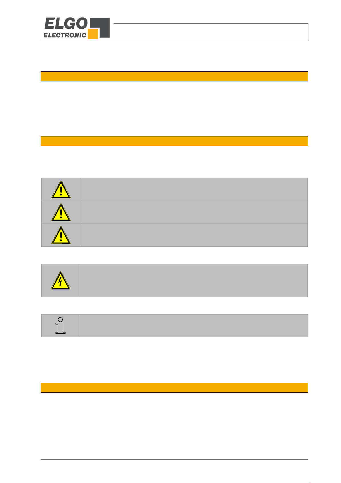
DANGER!
This symbol in connection with the signal word “Danger” indicates an immediate danger for the life and health of
persons. Failure to heed these instructions can result in serious damage to health and even fatal injury.
WARNING!
This symbol in connection with the word „Warning” means a possibly impending danger for the life and health of
persons. Failure to heed these instructions can result in serious damage to health and even fatal injury.
CAUTION!
This symbol in connection with the signal word “Caution” indicates a possibly dangerous situation. Failure to heed
these instructions can lead to minor injuries or damage of property.
DANGER!
This symbol in connection with the signal word “Danger” indicates an immediate danger for the life and health of
persons due to voltage.
Failure to heed these instructions can result in serious damage to health and even fatal injury. The operations may
only be carried out by a professional electrician.
NOTE!
…points out useful tips and recommendations as well as information for an efficient and trouble-free operation.
2 General, Safety, Transport and Storage
2.1 Information Operating Manual
This manual contains important information regarding the handling of the device. For your own safety and operational safety, please observe all safety warnings and instructions.
Precondition for safe operation is the compliance with the specified safety and handling instructions.Moreover, the existing local accident
prevention regulations and the general safety rules at the site of operation have to be observed.
Please read the operating manual carefully before starting to work with the device! It is part of the product and should be kept close to the
device and accessible for the staff at any time. The illustrations in the manual are for better demonstration of the facts. They are not necessarily to scale and can slightly differ from the actual design.
2.2 Explanation of Symbols
Special notes in this manual are characterized by symbols.The notes are introduced by signal words which express the magnitude of danger.
Please follow this advice and act carefully in order to avoid accidents, damage, and injuries.
Warning notes:
Special safety instructions:
Tips and recommendations:
Reference marks:
Marks a reference to another chapter of this manual.
Marks a reference to another chapter of another document.
2.3 Statement of Warranties
The producer guarantees the functional capability of the process engineering and the selected parameters.
General, Safety, Transport and Storage
- 5 -
CAUTION!
Wrong disposal causes environmental damages!
Electronic scrap, electronic components, lubricants and other auxiliary materials are subject to special refuse and can
only be disposed by authorized specialists!
CAUTION!
Please read the operating manual carefully, before using the device! Observe the installation instructions! Only start
up the device if you have understood the operating manual. The operating company is obliged to take appropriate
safety measure.
The initial operation may only be performed by qualified and trained staff.
Selection and installation of the devices as well as their embedding into the controlling system require qualified
knowledge of the applicable laws and normative requirements on the part of the machine manufacturer.
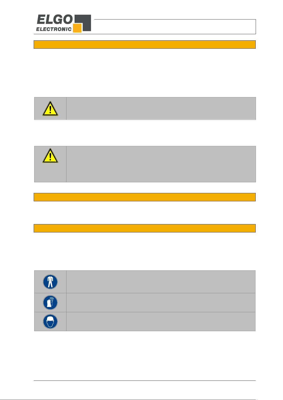
PROTECTIVE CLOTHING
… is close-fitting working clothing with light tear strength, tight sleeves and without distant parts.
It serves preliminarily for protection against being gripped by flexible machine parts.
Do not wear rings, necklaces or other jewellery.
PROTECTIVE GLOVES
…for protecting the hands against abrasion, wear and other injury of the skin.
PROTECTIVE HELMET
…for protection against injuries of the head.
2.4 Demounting and Disposal
Unless acceptance and disposal of returned goods are agreed upon, demount the device considering the safety instructions of this manual
and dispose it with respect to the environment.
Before demounting, disconnect the power supply and secure against re-start. Then disconnect the supply lines physically and discharge
remaining energy. Remove operational supplies and other material.
Disposal:
Recycle the decomposed elements: Metal components in scrap metal, Electronic components in electronic scrap, Recycle plastic components, Dispose the remaining components according to their material consistence
Local authorities and waste management facilities provide information about environmentally sound disposal.
Safety
2.5 General Causes of Risk
This chapter gives an overview of all important safety aspects to guarantee an optimal protection of employees and a safe and trouble-free
operation. Non-observance of the instructions mentioned in this operating manual can result in hazardous situations.
2.6 Personal Protective Equipment
Employees have to wear protective clothing during the installation of the device to minimize danger of health.
Therefore:
Change into protective clothing before performing the works and wear them throughout the process.
Additionally observe the labels regarding protective clothing in the operating area.
Protective clothing:
General, Safety, Transport and Storage
- 6 -
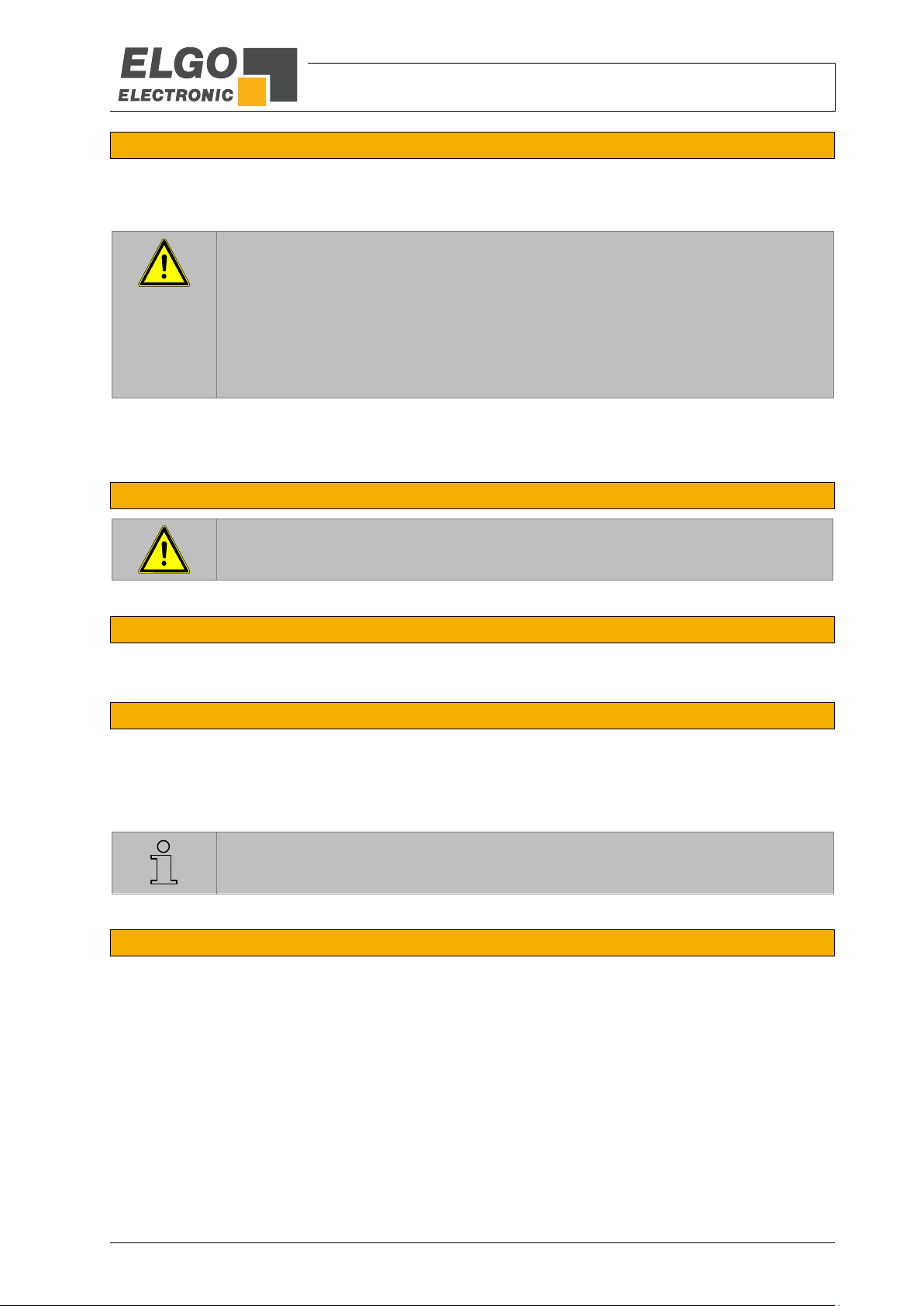
CAUTION!
Danger through non-conventional use!
Non-intended use and non-observance of this operating manual can lead to dangerous situations.
Therefore:
Only use the device as described
Strictly follow the instructions of this manual
Avoid in particular:
Remodelling, refitting or changing of the construction or single components with the intention to alter the
functionality or scope of the device.
CAUTION!
Transport the package (box, palette etc.) professionally.
Do not throw, hit or fold it.
NOTE!
Claim any damage immediately after recognizing it. The claims for damage must be filed in the lawful reclaim periods.
2.7 Conventional Use
The product described in this manual was developed to execute safety-related functions as a part of an entire assembly or machine. It is the
responsibility of the manufacturer of a machine or installation to ensure the proper functioning of the system. The ELGO-device is only
conceived for the conventional use described in this manual. The FMAX - ELGO- length measuring system only serves to measure lengths.
Claims resulting from damages due to non-conventional use are not possible.
Only the operator is liable for damages caused by non-conventional use.
2.8 Safety Instructions for Transport, Unpacking and Loading
2.9 Handling of Packaging Material
Notes for proper disposal: 2.4
2.10 Inspection of Transport
Check the delivery immediately after the receipt for completeness and transport damage.
In case of externally recognizable transport damages:
Do not accept the delivery or only accept under reserve.
Note the extent of damages on the transportation documents or delivery note.
File complaint immediately.
2.11 Storage
Store the device only under the following conditions:
Do not store outside
Keep dry and dust-free
Do not expose to aggressive media
Protect from direct sun light
Avoid mechanical shocks
Storage temperature ( 4.4) needs to be observed
Relative humidity ( 4.4) must not be exceeded
Inspect packages regularly if stored for an extensive period of time (>3 months)

Product Features
- 7 -
S N S N S N S N S N S N S N S N S N S N
S N S N
S N S N S N S N S N S N S N S N S N S N
S N S N
S N S N S N S N S N S N S N S N S N S N
S N S N
S
Track 1
Track 2
Track 3
N
S
S
0
0
U
1
U
2
U
3
Sensor 1
Sensor 2
Sensor 3
L = max. 650 mm
X
∆ X
3 Product Features
Series FMAX is an absolute magnetic length measuring system and only of use for recordation of lengths. It consists of a guide carriage, where sensor technology and translator are placed, and a guide rail FSMAB. A magnetic tape is installed on the guide rail. The guide carriage is guided contactless over the magnetic tape.
Typical applications are paper cutting machines, hydraulic presses, wood- and sheet metal processing machines.
Overview of features:
no reference adjustment necessary
direct measurement
measuring lengths up to 650 mm
high resolution up to 0.01 mm
repeating accuracy +/- 0.01 mm
protection against dirt and dust
easy installation
Interfaces: RS232, RS422 and SSI ( 9.1)
3.1 Functional Principle
Three sensors are guided over a magnetic tape, recorded with three tracks. The following illustration shows the
three magnetic tracks with following north- and South Pole magnetization, sensed by magneto-resistive resistor
measuring bridges. Between the single magnetic tracks there always is an equal shifting X. This is evaluated
together with the single signs of the resistive resistor measuring bridges and delivers an absolute value. An unambiguous classification of a absolute position is possible by the combination of the phasing of the three magnetic tracks. The phase position zero repeats every 650 mm for each of the three tracks.
Figure 1: Functional Principle

Technical Data
- 8 -
5
43
48
25
25
22
5
75
80
90
4
8
48
20
25
6
6
8 4
1,7
6
25
20
±0,1
+0,3
0
1,7
±0,1
10,2
+0,3
0
12
1,5
9,5
12
4
5
5
4 Technical Data
4.1 Identification
The type label serves for the identification of the unit. It is located on the housing of the sensor and shows the
exact type designation (=order reference, 9.1). Furthermore, the type label contains a unique, traceable
device number, the production date as well as the hardware and software versions. When corresponding with
ELGO always indicate this data.
4.2 Dimensions Sensor
Figure 2: Top view
Figure 3: Front and back view
4.3 Dimensions of Guide Rail FSMAB (Accessory)
Figure 4: Dimensions of FSMAB (accessory)

Technical Data
- 9 -
FMAX (Standard version)
Mechanical Data
Measuring principle
absolute
Measurement
linear
Maximum measuring length
650 mm
Speed
max. 0.5 m/s
Output frequency
500 Hz (20 ms)
Resolution
0.01 mm
Repeat accuracy
+/- 0.01 mm
System accuracy in µm at 20°C
+/- (50 µm + 20 µm x L)
L = measuring length in meter
Dimensions
sensor/guide carriage
L x W x H = 90 x 48 x 28 mm
Housing
zinc die-cast, black
Guide rail
aluminium profile
Connection
open cable ends
Connection cable
drug chain suitable
length 30.0 m max.
weight: approx. 58.0 g/m
2 x 0.75 mm², 6 x 0.14 mm²
radial flexibility 60 mm min.
Weight
approx. 200 g without cable/guide carriage
cable approx. 60 g/m
guide rail with magnetic tape approx. 390 g/m
Magnetic tape
Necessary type
FMAB
(factory made the magnetic tape is stick together with the profile rail)
Expansion coefficient
= 16 x 10
-6 K-1
Thermal length expansion
L = L x x
Environment Conditions
Storage temperature
-25 °C ... +85 °C
Operation temperature
-10 °C ... +70 °C
(-25 °C ... +85 °C upon request)
Humidity
max. 80 %, non-condensing
Protection class
IP54
IP65 with option V ( 9.1)
Electrical Data
Supply voltage:
+ 10 ... 30 VDC
Residual ripple:
10 … 30 V: <10%
Power input:
max. 150 mA
Interfaces:
RS422, RS232, SSI
4.4 Technical Data Sensor
Table 1: Technical Data Sensor

Technical Data
- 10 -
Show no or little effect in constant contact after 2-5 years:
Formic acid
Glycerol 93°C
Linseed oil
Soy beans oil
Cotton seed oil
N-hexane
Lactic acid
Formaldehyde 40%
Iso-octane
Petroleum
Show weak to moderate effects in constant contact after approximately 1 year:
Acetone
Petrol/gasoline
Acetic acid 30%
Oleic acid
Acetylene
Steam
Acetic acid (pure)8
Sea water
Ammonia
Acetic acid 20%
Isopropyl ether
Stearic acid 70°C,
anhydrous
Kerosene
Have strong effects when contacting permanently after 1-5 months:
Benzene
Nitric acid 70%
Turpentine
Toluene
Lacquer solvent
Nitric acid, red, vitriolic
Carbon tetrachloride
Tetrahydrofuran
Trichloroethylene
Nitrobenzene
Hydrochloric acid 37%,
93°C
Xylene
CAUTION
Please read the operating manual carefully before using the device! Strictly observe the Installation instructions! In case of damage caused by failure to observe this operating manual, the
warranty expires.
ELGO is not liable for any secondary damage and for damage to persons, property or assets.
The operator is obliged to take appropriate safety measures. The first start-up may only be
performed by staff that has been trained and authorized by the operator.
WARNING!
Do not use the device in explosive or corrosive environments!
The device must not be installed close to sources of strong inductive
or capacitive interference or strong electrostatic fields!
4.4.1 Resistance of magnetic tape against chemical influences
Table 2: Resistance of magnetic tape against chemical influences
5 Installation and First Start-Up
5.1 Operating Area

Technical Data
- 11 -
CAUTION!
The electrical connections must be made by suitably qualified personnel in accordance with
local regulations.
The device may be designed for switchboard mounting. During work on the switchboard, all
components must be de-energized if there is a danger of touching the energized parts (protection against contacts)!
Wiring works may only be performed in the de-energized state!
Thin cable strands have to be equipped with end sleeves!
Before switching on the device, connections and plug connectors have to be checked!
The device must be mounted in a way that it is protected against harmful environmental influences such as splashing water, solvents, vibration, shock and severe pollution and the operating temperature must not be exceeded.
WARNING!
Do not use the device in explosive or corrosive environments!
The device must not be installed close to sources of strong inductive or capacitive interference
or strong electrostatic fields!
NOTE!
For installation of guide carriage and guide rail pay attention to the markings on the
magnetic tape and on the sensor. A wrong installation will deliver incorrect values.
5.2 Assembly Site
At least 0.5 m away from inductive and capacitive disturbance sources like contactors, relays, motors, switching
power supplies, clocked controllers, etc. In principle lay the FMAX-cable separated from power wires and keep
distance to disturbance sources. For installation near outside magnets, a minimum distance to the magnetic
tape of 100 mm is necessary.
5.3 Mounting of Guide Carriage
Take four M4-screws to fasten the guide carriage. .
5.4 Mounting of Guide Rail
The guide rail contains a magnetic tape and a profile rail. Factory made the magnetic tape is stick together with
the profile rail.
Take four M4-screws to fasten the guide rail. For that, there are drill hole at the ends.

Interfaces
- 12 -
T
Tm-T/2
1 1 G23 G22 G21 G20 G19 G18 G17 G16 G15 G14 G13 G12 G11 G10 G9 G8 G7 G6 G5 G4 G3 G2 G1 G0 PFB 0 1
1 2 3 4 5 6 7 8 9 10 11 12 13 14 15 16 17 18 19 20 21 22 23 24 25
Non-inverted SSI-Clock
+ 1 Power Failure Bit
24 Bit
PFB = Power failure bit
T = Cycle duration of the clock signal
TM = Monoflop time >15 µs
The “block check sum” is an „Exclusive OR” of all data inclusive STX and ETX.
All values will be transferred in ASCII-format.
Not inverted SSI Clock
6 Interfaces
The following chapters give detailed information about the available interfaces.
6.1 Interface RS422 (Option 4220) and RS232 (Option 2320)
Depending on order information the measuring system can be equipped with an RS422 or an RS232 interface.
Both variants use the same protocol and differ only in their level height. The data transfer has the following format:
9600 Baud
1 Start Bit
8 Data Bits
1 Stop Bit
No Parity
Data record:
The actual value will be transferred every 20 ms with the following data record:
02h STX
xxh ABS-Data
xxh ABS-Data
xxh ABS-Data
xxh ABS-Data
xxh ABS-Data
xxh ABS-Data
03h ETX
xxh BCC
6.2 Interface SSI (Option SSB0 and SSG0)
Principle of the function: If the clock is not interrupted for the time Tm-T/2 (output of further 25 periods), the shift
register clocks once again the same data value (error recognition in evaluation).
Some encoders contain a Power Failure Bit (PFB):
With FMAX the PFB is always „low“.
Figure 5: Function of the SSI interface

Connections
- 13 -
Cable
RS232 (Option 2320)
RS422 (Option 4220)
SSI (Option SSB0, SSG0)
white
0 V / GND
0 V / GND
0 V / GND
brown
+ 10 … 30 VDC
+ 10 … 30 VDC
+ 10 … 30 VDC
grey
TX-
DATA -
black
TX
DATA +
green
RX
RX-
CLOCK +
yellow
TX
RX
CLOCK -
7 Connections
7.1 Pin Assignment
Table 3: Pin assignment

Connections
- 14 -
NOTE
On delivery guide carriage and guide rail are numbered and belong together in pairs.
A teaching procedure is necessary, if only the guide rail or the guide carriage has to be replaced.
NOTE
This offset adjustment needs to be carried out at any change of guide carriage or guide rail.
In case the counting direction cannot be changed in the controller, the complete slide-system
has to be turned over.
7.2 Teaching Procedure/Offset
Should the desired display value differ from the factory-made adjusted original offset, a settlement can be carried out by the external counting unit. Alternatively the offset can be changed by the RS422 interface of the
FMAX.
7.2.1 Teaching Procedure
The teaching procedure has to be carried out as follows:
1. Guide carriage and guide rail are installed and the measuring system can stand at any place.
2. Afterwards the following record has to be sent to the measuring system:
02h STX
4ch „L“ = teaching procedure is started
03h ETX
4dh „M“ = BCC
3. The guide carriage has to be moved 30 mm in one direction with a speed of 0,01 m/s max. (10
mm/sec. max.) and then back again.
4. Afterwards the following record must be transmitted to the measuring system:
02h STX
42h „B“ = teaching procedure is finished
03h ETX
43h „C“ = BCC
5. The teaching procedure is completed.
7.2.2 Offset
After installation and connection of guide carriage and guide rail a value will be transferred over the interface.
As this value does not agree with the machine offset, an offset can be deposited usually at the controller side or
directly at the measuring system. In order to adjust this offset at the measuring system, the sensor has to be
moved to the machine offset.
Afterwards the following record must be transmitted:
02h STX
4eh „N“ = adjust zero point
03h ETX
4fh „O“ = BCC
The measuring system is adjusted to the machine offset. All transmitted values are now related from this offset.

Disturbances, Maintenance, Cleaning
- 15 -
CAUTION!
The device, the connection line and the signal cable must not be installed next to sources of interference that emit
strong inductive or capacitive interference or strong electrostatic fields.
External interferences can be avoided by a suitable cable routing.
The screen of the signal output cable should only be connected only on one side to the following circuit. The screens
must not be grounded on both sides. Signal cables always have to be routed separately from the load power line. A
safety distance of at least 0,5 m has to be kept from inductive and capacitive interference sources, e. g. contactors,
relays, motors, switching power supplies, clocked controllers etc!
If interferences occur in spite of all the items stated above being observed, please proceed as follows:
1. Installation of RC-circuits via contactor coils of AC-contactors (e.g. 0,1 µF / 100 Ω)
2. Installation of recovery diodes via DC-inductors
3. Installation of RC-circuits via the different motor phases (in the terminal box of the motor)
4. Do not connect protective earth and ground
5. Connect a mains filter ahead of the external power pack
WARNING!
Danger of injury through non-conventional fault clearance!
Non-conventional fault clearance can lead to severe injuries and damage of property.
Therefore:
Any work to clear the faults may only be performed by sufficiently qualified staff
Arrange enough space before starting the works
Make sure that the mounting area is clean and tidy. Loose components and tools are sources of accidents.
If components need to be replaced:
Pay attention to a correct installation of the spare parts.
Reinstall all the fixing elements properly
Before turning on the device, ensure that all covers and safety equipment is installed correctly and functions
properly
8 Disturbances, Maintenance, Cleaning
This chapter describes possible causes for disturbances and measures for their removal. In case of increased disturbances, please follow the
measures for fault clearance in chapter 8.1.
In case of disturbances that cannot be eliminated by following the advice and the fault clearance measures given here, please contact the
manufacturer (see second page).
8.1 Fault Clearance
8.2 Re-start after Fault Clearance
After the fault clearance:
1. Reset the emergency stop mechanism if necessary
2. Reset the error report at the super-ordinate system if necessary.
3. Ensure that there are no persons in the danger area.
4. Follow the instructions from chapter 5.

Disturbances, Maintenance, Cleaning
- 16 -
WARNING!
Danger through non-conventional maintenance!
Non-conventional maintenance can lead to severe injuries and damage of property.
Therefore:
Maintenance works may only be completed by staff that has been authorized and trained by the operator.
WARNING!
The device can only be cleaned with a damp cloth, do not use aggressive cleanser!
8.3 Maintenance
The device is maintenance-free.
8.4 Cleaning

Type Designation
- 17 -
NOTE
When ordering, please use the here described ordering code (Type Designation). Options
that are not required are filled in with „-„.
Order designation
Description
FSMAB-XXXX*
Guide rail for FMAX (total length = measuring length + 150 mm)
*) XXXX = measuring length in mm; 0650 = max. possible length of 650 mm)
FMAX XX XXX XXXX XXXX X-- - - -
Series/Type:
FMAX Measuring System
SN-number:
00 = Standard
01 = 1. special version
Signal cable length:
030 = 3.0 m
050 = 5.0 m
080 = 8.0 m
100 = 10.0 m
Resolution:
0010 = 0.01 mm
Interface:
2320 = RS232
4220 = RS422
SSG0 = SSI gray code
SSB0 = SSI binary code
Options:
(Multiple choices possible)
U = unguided version
V = sealed version
9 Type Designation
9.1 Type Designation Sensor
Figure 6: Type designation sensor
9.2 Guide Rail FSMAB (Accessory)
Table 4: Guide rail FSMAB

- 18 -
Notes:

Index
- 19 -
10 Index
Accident prevention regulations........................... 4
Causes of risk .................................................... 5
Cleaning ................................................... 15, 16
Conventional use ............................................... 6
Demounting ...................................................... 5
Device number .................................................. 8
Dimensions ....................................................... 8
Disposal............................................................ 5
Disturbances ................................................... 15
Explanation of symbols ....................................... 4
Fault clearance ................................................ 15
First start-up .................................................... 10
Functional Principle ............................................ 7
Guide Carriage installation .............................. 11
Guide Rail installation ...................................... 11
Identification ..................................................... 8
Installation ...................................................... 10
Interfaces ........................................................ 12
Maintenance ............................................. 15, 16
Operating area ......................................... 10, 11
Operational safety ............................................. 4
Order reference ................................................ 8
Packaging material ............................................ 6
Product features ................................................ 7
Protection against contact ................................ 11
Protective equipment ......................................... 5
Resistance against chemical influences .............. 10
Safety ........................................................... 4, 5
Safety instructions .............................................. 4
Safety rules ....................................................... 4
Sensor technical data ........................................ 9
Start-up .......................................................... 10
Storage ............................................................ 6
Teaching Procedure/Offset .............................. 14
Transport .......................................................... 6
Transport damage ............................................. 6
Type designation ............................................... 8

- 20 -
Document- No.:
799000042 / Rev. 6
Document- Name :
FMAX-00-MA-E_50-18
Subject to change - © 2018
ELGO Electronic GmbH & Co. KG
EL G O Elec t r onic Gm bH & C o . KG
Me as uri ng | Posi tio ni ng | Co ntr ol
Carl - Ben z - S tr. 1, D-7 823 9 Ri elasing en
Fon:+49 (0) 7731 9339-0, Fax:+49 (0) 7731 28803
Internet: www.elgo.de, Mail: info@elgo.de
 Loading...