

ELGO Electronic EMIX2 series Operating Manual

Operating Manual
SERIES EMIX2
Magnetic Incremental Length Measuring System with 0.01mm resolution
Direct contact-free measurement
Distance range between sensor and magnetic tape: 0.1 to 0.8 mm
High resolution of 0.01 mm
Repeat accuracy +/- 0.01 mm
Very resistant against dirt
799000076 / Rev. 4 / 2017-05-11
Translation of the original operating manual

- 2 -
Publisher
ELGO Electronic GmbH & Co. KG
Carl-Benz-Str. 1
D-78239 Rielasingen-Worblingen
Technical Support
+49 (0) 7731 9339 – 0
+49 (0) 7731 2 13 11
info@elgo.de
Document- No.
799000076
Document- Name
EMIX2-000-MA-E_19-17
Document- Revision
Rev. 4
Issue Date
2017-05-11
Copyright
© 2017, ELGO Electronic GmbH & Co. KG

Contents
- 3 -
1 Contents
1 Contents ............................................................................................. 3
2 General, Safety, Transport and Storage ........................................... 4
2.1 Information Operating Manual ............................................................................. 4
2.2 Explanation of Symbols ........................................................................................ 4
2.3 Statement of Warranties ....................................................................................... 5
2.4 Demounting and Disposal .................................................................................... 5
2.5 General Causes of Risk ........................................................................................ 5
2.6 Personal Protective Equipment ............................................................................... 5
2.7 Conventional Use ............................................................................................... 6
2.8 Safety Instructions for Transport, Unpacking and Loading .......................................... 6
2.9 Handling of Packaging Material ............................................................................ 6
2.10 Inspection of Transport ........................................................................................ 6
2.11 Storage ............................................................................................................. 6
3 Product Features ................................................................................ 7
3.1 Functional Principle ............................................................................................. 7
3.2 Pulse Diagram .................................................................................................... 7
4 Technical Data ................................................................................... 8
4.1 Identification ...................................................................................................... 8
4.2 Dimensions Sensor .............................................................................................. 8
4.3 Technical Data Sensor ......................................................................................... 9
4.4 Technical Data Magnetic Tape ............................................................................ 10
5 Installation and First Start-Up ......................................................... 11
5.1 Operating Area ................................................................................................ 11
5.2 Installation of the Magnetic Tape ......................................................................... 12
5.3 Installation of the Sensor .................................................................................... 15
6 Connections ...................................................................................... 17
6.1 Pin Assignment ................................................................................................. 17
7 Disturbances, Maintenance, Cleaning ............................................. 18
7.1 Fault Clearance ................................................................................................ 18
7.2 Re-start after Fault Clearance .............................................................................. 18
7.3 Maintenance .................................................................................................... 19
7.4 Cleaning ......................................................................................................... 19
8 Type Designation ............................................................................. 20
8.1 Accessories ...................................................................................................... 20
9 Index ................................................................................................ 23
General, Safety, Transport and Storage
- 4 -
DANGER!
This symbol in connection with the signal word “Danger” indicates an immediate danger for the life and health of
persons. Failure to heed these instructions can result in serious damage to health and even fatal injury.
WARNING!
This symbol in connection with the word „Warning” means a possibly impending danger for the life and health of
persons. Failure to heed these instructions can result in serious damage to health and even fatal injury.
CAUTION!
This symbol in connection with the signal word “Caution” indicates a possibly dangerous situation. Failure to heed
these instructions can lead to minor injuries or damage of property.
DANGER!
This symbol in connection with the signal word “Danger” indicates an immediate danger for the life and health of
persons due to voltage.
Failure to heed these instructions can result in serious damage to health and even fatal injury. The operations may
only be carried out by a professional electrician.
NOTE!
…points out useful tips and recommendations as well as information for an efficient and trouble-free operation.
2 General, Safety, Transport and Storage
2.1 Information Operating Manual
This manual contains important information regarding the handling of the device. For your own safety and operational safety, please observe all safety warnings and instructions. Precondition for safe operation is the compliance with the specified safety and handling instructions. Moreover, the existing local accident prevention regulations and the general safety rules at the site of operation have to be observed.
Please read the operating manual carefully before starting to work with the device! It is part of the product and should be kept close to the
device and accessible for the staff at any time. The illustrations in the manual are for better demonstration of the facts. They are not necessarily to scale and can slightly differ from the actual design.
2.2 Explanation of Symbols
Special notes in this manual are characterized by symbols.
The notes are introduced by signal words which express the magnitude of danger.
Please follow this advice and act carefully in order to avoid accidents, damage, and injuries.
Warning notes:
Special safety instructions:
Tips and recommendations:
Reference marks:
Marks a reference to another chapter of this manual.
Marks a reference to another chapter of another document.
General, Safety, Transport and Storage
- 5 -
CAUTION!
Wrong disposal causes environmental damages!
Electronic scrap, electronic components, lubricants and other auxiliary materials are subject to special refuse and can
only be disposed by authorized specialists!
CAUTION!
Please read the operating manual carefully, before using the device! Observe the installation instructions! Only start
up the device if you have understood the operating manual. The operating company is obliged to take appropriate
safety measure.
The initial operation may only be performed by qualified and trained staff.
Selection and installation of the devices as well as their embedding into the controlling system require qualified
knowledge of the applicable laws and normative requirements on the part of the machine manufacturer.
PROTECTIVE CLOTHING
… is close-fitting working clothing with light tear strength, tight sleeves and without distant parts. It serves preliminarily for protection against being gripped by flexible machine parts.
Do not wear rings, necklaces or other jewellery.
PROTECTIVE GLOVES
…for protecting the hands against abrasion, wear and other injury of the skin.
PROTECTIVE HELMET
…for protection against injuries of the head.
2.3 Statement of Warranties
The producer guarantees the functional capability of the process engineering and the selected parameters.
2.4 Demounting and Disposal
Unless acceptance and disposal of returned goods are agreed upon, demount the device considering the safety instructions of this manual
and dispose it with respect to the environment.
Before demounting, disconnect the power supply and secure against re-start. Then disconnect the supply lines physically and discharge
remaining energy. Remove operational supplies and other material.
Disposal:
Recycle the decomposed elements: Metal components in scrap metal, Electronic components in electronic scrap, Recycle plastic components, dispose the remaining components according to their material consistence.
Local authorities and waste management facilities provide information about environmentally sound disposal.
Safety
2.5 General Causes of Risk
This chapter gives an overview of all important safety aspects to guarantee an optimal protection of employees and a safe and trouble-free
operation. Non-observance of the instructions mentioned in this operating manual can result in hazardous situations.
2.6 Personal Protective Equipment
Employees have to wear protective clothing during the installation of the device to minimize danger of health.
Therefore:
Change into protective clothing before performing the works and wear them throughout the process.
Additionally observe the labels regarding protective clothing in the operating area.
Protective clothing:
General, Safety, Transport and Storage
- 6 -
CAUTION!
Danger through non-conventional use!
Non-intended use and non-observance of this operating manual can lead to dangerous situations.
Therefore:
Only use the device as described
Strictly follow the instructions of this manual
Avoid in particular:
Remodelling, refitting or changing of the construction or single components with the intention to alter the
functionality or scope of the device.
CAUTION!
Transport the package (box, palette etc.) professionally. Do not throw, hit or fold it.
NOTE!
Claim any damage immediately after recognizing it. The claims for damage must be filed in the lawful reclaim periods.
2.7 Conventional Use
The ELGO-device is only conceived for the conventional use described in this manual.
The EMIX2 - ELGO- length measuring system only serves to measure lengths and distances.
Claims resulting from damages due to non-conventional use are not possible.
Only the operator is liable for damages caused by non-conventional use.
2.8 Safety Instructions for Transport, Unpacking and Loading
2.9 Handling of Packaging Material
Notes for proper disposal: 2.4
2.10 Inspection of Transport
Check the delivery immediately after the receipt for completeness and transport damage.
In case of externally recognizable transport damages:
Do not accept the delivery or only accept under reserve.
Note the extent of damages on the transportation documents or delivery note.
File complaint immediately.
2.11 Storage
Store the device only under the following conditions:
Do not store outside
Keep dry and dust-free
Do not expose to aggressive media
Protect from direct sun light
Avoid mechanical shocks
Storage temperature (4) needs to be observed
Relative humidity (4) must not be exceeded
Inspect packages regularly if stored for an extensive period of time (>3 months)
Product Features
- 7 -
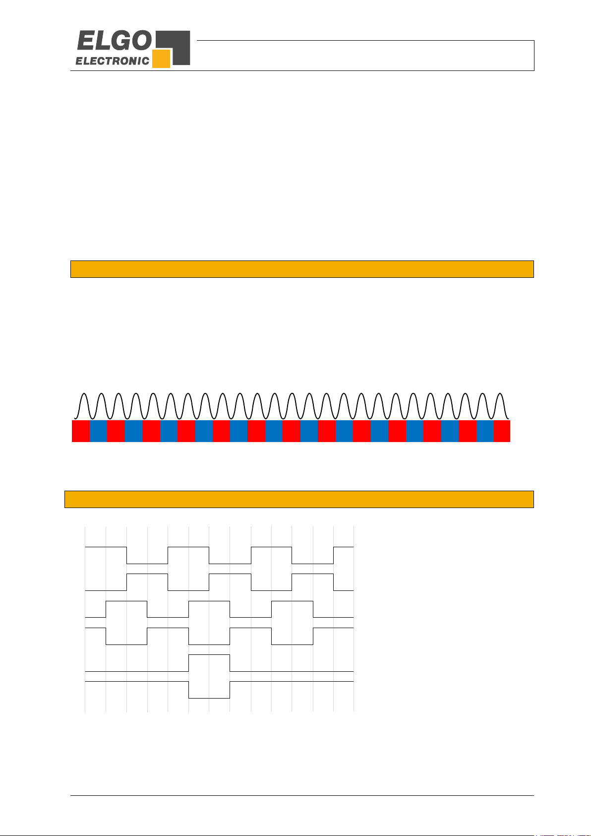
N N N NS S S S N N N NS S S S N NS SN NS SS
B
B‘
Z
Z‘
A
A‘
Channel A and B are
phase shifted by 90°
The index pulse output is
periodically every 2 mm
3 Product Features
The EMIX2 is an incremental magnetic length measuring system. The sensor technology and translator circuit are
placed in the same small housing. The magnetic tape can also be fixed into a guiding rail by using the provided
adhesive tape. The EMIX2 can be installed up to a maximum distance of 0.8 mm to the magnetic tape.
Overview of features:
Direct contactless measurement
The distance between sensor and measuring tape can vary between 0.1 and 0.8 mm
Measuring length theoretical unlimited
High resolution of 0.01 mm
Repeating accuracy +/- 0.01 mm
Very robust against pollution
3.1 Functional Principle
The basis of the magnetic incremental encoders consists of a scanning technology, which scans the north and
south poles on the coded magnetic tape and produces a single Sine/Cosine wave for each pole.
The complete sine/cosine signal process is interpolated electronically. Depending on refinement of the interpolation, together with the pole distance of the magnetic tape, the resolution of the measuring system is determined.
The magnetic tape ( 4.4) has a pole pitch of 2 mm. A special evaluation electronic (translator) processes the
sine/cosine wave into square output signals from the signal information of the magnetic tape. These square
signals are equivalent to conventional optical rotary- or linear encoder outputs.
Figure 1: Magnetic tape
3.2 Pulse Diagram
Figure 2: Pulse diagram
Technical Data
- 8 -
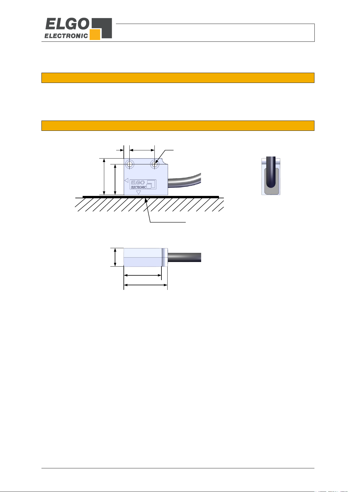
30
12.5
Magnetic Tape
17
4
21
25
25
Ø3.4
4 Technical Data
4.1 Identification
The type label serves for the identification of the unit. It is located on the housing of the sensor and gives the
exact type designation (=order reference, 8) with the corresponding part number. Furthermore, the type label
contains a unique, traceable device number. When corresponding with ELGO please always indicate this data.
4.2 Dimensions Sensor
Figure 3: Dimensions Sensor
 Loading...