

ELGO Electric AZ16I series Installation Manual
I series
Installation manual
Battery operated
ABSOLUTE - Linear encoder and indicator System
with integrated sensor and magnetic tape guidance
Features
• Measuring distances up to 8 meters possible
• Unique definition of the zero point
(no further referencing necessary)
• Permanent retention of all data and settings
• Reserve energy up to 4 years
• AUTO-POWER-OFF function with adjustable „switch on“ time
• Switch over for absolute / incremental mode
• Millimeters or Inches operation
• Fraction views in the Inch mode possible
• User friendly menu levels
• Completely guided by magnetic tape guidance rail
• Key can be enabled or disabled individually
• Adjustable reference value and 3 tool offsets
• Symbols individually selectable (mm/inches/arrows etc.)
• Costumer specified housing and guidance possible
AZ16I-000-E_10-06.doc Doku Art. Nr. 799000023

1. INTRODUCTION 3
2. SAFETY 3
3. DETERMINATION OF THE RAIL AND TAPE LENGTH 4
3.1 Complete assembled guide rail 4
3.2 Guide rail and Magnetic tape - Self assembling 4
5. THE AZ16I IN OPERATION 5
5.1 Initial operation 5
5.1.1 Detection of measuring direction 5
5.1.2 Referencing 5
5.3 Parameter settings 7
6. BATTERY CHANGE 9
7. MAGNETIC TAPE 10
Handling 10
Processing note for sticking 11
Resistance to chemicals of the magnetic tape 11
Sticking and cutting 11
7. TECHNICAL SPECIFICATIONS (PRELIMINARY) 12
9. TYPE DESIGNATION 13
10. LIABILITY EXCLUSION / GUARANTEE 14
2
1. Introduction
The new linear „Absolute“ encoder and indicator unit AZ16 is based on the proven magnetic
measuring principle. According to its battery supply, no wirings are necessary and the systems
is able to operate as a complete stand alone unit. The max. possible measuring distance
amounts to 8 meters. By using the AUTO-POWER-OFF mode the max. service life span of the
battery amounts up to 4 years.
The magnetic sensor is integrated in the indicator housing. Further a version with an external
sensor is available (AZ16E).
Characteristics of the AZ16I variant (integrated sensor):
For recording of measurement a guide rail in suitable length is provided (please indicate when
order). The maximum length of a guide rail amounts to 2 m. It is possible to reach the max.
measuring distance of 8 m by arranging 4 single 2 m rails in one line.
Guide rails up to 2 meters are already assembled with the necessary magnetic tape. In case of
longer measuring lengths, the tape is delivered separately an must fitted by the costumer himself.
The guideway for the rail is located on the rear of the indicator unit.
On request the system can be supplied also without guidance and guide rail, then the user
must provide and guarantee for a suitable mechanical guiding system. It must be ensured, that
the sensor (integrated in the indicator) keeps the correct distance (0... 1.5 mm) along the
whole measuring distance coplanar to the magnetic tape.
2. Safety
Please note: Before first commissioning read this installation manual carefully and
observe absolutely the installation instructions. The measuring system is only dedicated for recording lengths. The type label is intended for exact identification of the
measuring system. The label is situated on the indicator housing. It informs about
the exact type designation (see chapter 9), the delivery date and the production
number. When contacting the company ELGO Electric GmbH please use these
terms.
Attention!
The company ELGO Electric GmbH is not liable for possible damages to machines
and or to persons, which can result from defective material at the measuring system and the following circuit. The machine manufacturer is responsible for taking
and realizing the necessary safety precautions.
3
3. Determination of the rail and tape length
Basically the following applies with an order of magnetic tape:
Ordered length of tape = effective measuring distance + 100 mm
For further details see the „Type designation“ at the end of the manual.
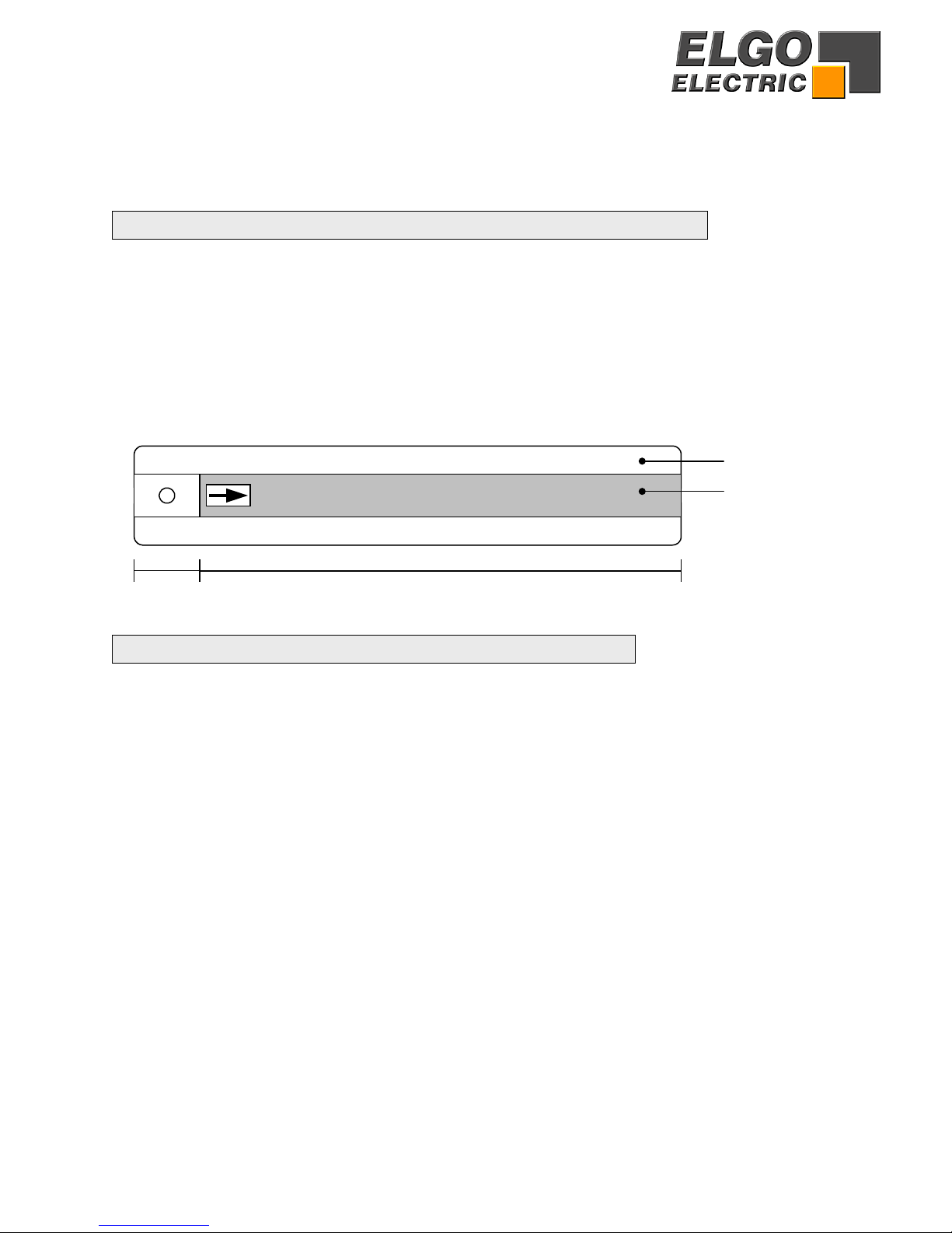
3.1 Complete assembled guide rail
(for effective measuring distances up to 1.885 m)
With measuring distances < 2 m (effective 1.885 m), the guide rail is already factory-assembled
with the magnetic tape. The side of the zero point is provided with a 4.2 mm mounting hole. For
this further 15 mm must be added.
15 mm Magnetic tape length = effective measuring length + 100 mm
The total length of the rail is calculated as follows:
Rail length = Ordering length of magnetic tape + 15 mm
Aluminium guide rail
Magnetic tape
3.2 Guide rail and Magnetic tape - Self assembling
(for effective measuring distances > 1.885 m)
If distances > 1,885 meters must be measured, the guide rail is multipart supplied, since for
transport-technical reasons only a maximum length of 2 m are possible. The single rail parts still
have no mounting holes. These must done by the user and also be fastened align at a suitable
place then.
The magnetic tape must be inserted after arraying the rail parts into the slot of the rails and stuck
together with the special sticky tape, attached at the magnetic tape. Subsequently for protection,
a cover band must be stuck together with the magnetic tape.
Included in delivery:
• Magnetic tape, sticky tape and cover band (order-related length)
• Aluminium profile rail parts (total length = ordered tape length + 15 mm)
Mounting:
1. Align and fasten the rail parts at the measuring place
2. Insert the magnetic tape into the rail slots
3. Detect the measuring direction (see chapter 5.1.1)
4. Stick the tape into the guide rail slot
5. Stick the cover band for protection
4

(
g)
4. Display assignment
battery condition direction arrow tool offset 3 (1, 2 or 3 possible)
absolute mode
sign measurement unit
5. The AZ16I in operation
5.1 Initial operation
5.1.1 Detection of measuring direction
On the magnetic tape is an arrow marker, which indicates the positive direction.
According to the following image, the arrow of the tape must show to the right.
The counting direction (+/-) can be changed by the register P01 (see chapter 5.4).
Front view
Marker
5156,9
Positive direction
when P01 = default settin
Magnetic Tape
5.1.2 Referencing
Setting the zero-point: A new AZ16I unit shows always the absolute value of the magnetic tape
and should be calibrated to the zero point at one time. The reference value default setting in register P09 is 0. To assign a zero point to an arbitrary position, move to the desired
zero-point and press the buttons F + Set together.
Reference value: Alternatively an arbitrary value can be entered in P09, to set a demanded reference measurement by pressing F + Set together.
5
 Loading...