


Operating Manual
LIMAX44 RED
Safe Magnetic Absolute Shaft Information System
(Translation of the original operating manual)
Redundant sensor with integrated monitoring
TÜV certified according to SIL 3 in compliance with EN 61508
Absolute position always directly available – no reference journey even af-
ter long power failures
RS-485 Interface
Easy and flexible installation
Silent measuring principle
Immune to dirt, smoke and moisture
Door zone indication for up to 127 floors
Speeds up to 16 m/s
D-103836 / Rev. 0 / 2019-06-03
799000969
Registration No.:
968/FSP 1850.00/19
- 1 -

Publisher
ELGO Batscale AG
Föhrenweg 20
FL-9496 Balzers
Technical Support
+49 (0) 7731 9339 – 0
+49 (0) 7731 2 13 11
support@elgo.de
Document- No.
D-103836
Document - Name
LIMAX44RED-02-MA-E_23-19
Article No.
799000969
Document- Revision
Rev. 0
Issue Date
2019-06-03
Copyright
© 2019, ELGO Batscale AG
- 2 -

Contents
1 Contents
1 Contents ............................................................................................. 3
2 General .............................................................................................. 5
2.1 Information Operating Manual ............................................................................. 5
2.2 Terms and Abbreviations ...................................................................................... 5
2.3 Explanation of Symbols ........................................................................................ 6
2.4 Referenced Documents ........................................................................................ 7
2.5 Statement of Warranties ....................................................................................... 7
2.6 Demounting and Disposal .................................................................................... 7
2.7 RoHS Conformity ................................................................................................ 7
3 Safety ................................................................................................. 8
3.1 General Causes of Risk ........................................................................................ 8
3.2 Personal Protective Equipment ............................................................................... 8
3.3 Conventional Use ............................................................................................... 9
4 Transport and Storage .................................................................... 10
4.1 Safety Instructions for Transport, Unpacking and Loading ........................................ 10
4.2 Handling of Packaging Material .......................................................................... 10
4.3 Inspection of Transport ...................................................................................... 10
4.4 Storage ........................................................................................................... 10
5 Product Features .............................................................................. 11
6 Technical Data ................................................................................. 14
6.1 Identification .................................................................................................... 14
6.2 Safety Parameters ............................................................................................. 14
6.3 Technical Data Magnetic Tape and Presence Detector ............................................ 14
6.4 Dimensions Sensor ............................................................................................ 16
6.5 Technical Data Sensor ....................................................................................... 18
6.6 Technical Data Magnetic Tape ............................................................................ 19
7 Type Designation ............................................................................. 21
7.1 Available Versions ............................................................................................. 21
8 Installation and First Start-Up ......................................................... 22
8.1 Operating Area ................................................................................................ 22
8.2 General Information .......................................................................................... 23
8.3 Mounting of the Magnetic Tape .......................................................................... 23
8.4 Mounting of the Magnetic Tape Presence Detector ................................................. 26
8.5 Mounting of the Sensor ...................................................................................... 27
8.6 Installation Procedure ........................................................................................ 29
9 Design and Functions ...................................................................... 37
9.1 Sensor Design .................................................................................................. 37
- 3 -

Contents
9.2 Operating Modes ............................................................................................. 39
9.3 LED Signals ...................................................................................................... 39
9.4 Door Zone Indication ........................................................................................ 42
9.5 Connections and Interfaces ................................................................................ 42
10 Requirements for Evaluation Unit ................................................... 51
10.1 Hardware Requirements ..................................................................................... 51
10.2 Software Requirements ....................................................................................... 51
11 Accessories ....................................................................................... 52
11.1 Mounting Kit Magnetic Tape (only semi-guided variant) .......................................... 52
11.2 Mounting Aid Sensor ......................................................................................... 53
11.3 Spare Material Sensor ....................................................................................... 53
11.4 Connection Cable............................................................................................. 53
12 Disturbances .................................................................................... 54
12.1 Error in Position Determination ............................................................................ 54
12.2 Non-severe Errors ............................................................................................. 54
12.3 Severe Errors .................................................................................................... 55
12.4 Informative Errors (not Safety-Relevant) ................................................................. 55
12.5 Fault Clearance ................................................................................................ 56
12.6 Possible Errors and their Clearance ...................................................................... 57
12.7 Re-start after Fault Clearance .............................................................................. 59
13 Maintenance .................................................................................... 60
14 Cleaning ........................................................................................... 60
15 Index ................................................................................................ 63
- 4 -

General
Abbreviation/
Term
Explanation
Verified position
See safe position data
CPU
Central Processing Unit
CRC
Cyclic Redundancy Check
EEPROM
Electrically Erasable Programmable Read-Only Memory (is used as non-volatile
data memory)
FS
Functional Safety
LSB
Least Significant Bit
Motorola format
When transmitting a value, the most significant byte is transmitted first. For a 32-bit
value it is for example bit 24 … bit 31
MSB
Most Significant Bit
MW
Mounting angle
RAM
Random Access Memory (main memory)
ROM
Read-Only Memory (program memory)
S-RMS
Mounting kit for rail mounting of the magnetic tape for safe sensors
(Safe Rail Mounting Set), can be used for the semi-guided variant.
Safe evaluation unit
Device that receives the safe position data of the sensor and cuts the safety circuit
in case of a disturbance. A safe position controller can fulfil the function of a safe
evaluation unit.
Safe position data
This position information may be used for safety functions.
Unsafe position data
Position information that may not be used for safety function due to missing redundancy.
Safe state
In this mode the danger for passenger and environment is minimized. In the elevator industry, safe state means that the safety circuit of the elevator is opened and
the cabin is stopped.
Since LIMAX44 RED has no direct connection, it has to be connected to the safety
circuit via the safe evaluation unit.
2 General
2.1 Information Operating Manual
This manual contains important information regarding the handling of the device.
For your own safety and operational safety, please observe all safety warnings and instructions.
Precondition for safe operation is the compliance with the specified safety and handling instructions.
Moreover, the existing local accident prevention regulations and the general safety rules at the site of operation
have to be observed.
Please read the operating manual carefully before starting to work with the device!
It is part of the product and should be kept close to the device and accessible for the staff at any time. The illustrations in the manual are for better demonstration of the facts. They are not necessarily to scale and can slightly
differ from the actual design.
2.2 Terms and Abbreviations
- 5 -

General
DANGER!
This symbol in connection with the signal word “Danger” indicates an
immediate danger for the life and health of persons.
Failure to heed these instructions can result in serious damage to
health and even fatal injury.
WARNING!
This symbol in connection with the word „Warning” means a possibly
impending danger for the life and health of persons.
Failure to heed these instructions can result in serious damage to
health and even fatal injury.
CAUTION!
This symbol in connection with the signal word “Caution” indicates a
possibly dangerous situation. Failure to heed these instructions can
lead to minor injuries or damage of property.
DANGER!
This symbol in connection with the signal word “Danger” indicates an
immediate danger for the life and health of persons due to voltage.
Failure to heed these instructions can result in serious damage to
health and even fatal injury. The operations may only be carried out by
a professional electrician.
NOTE!
… points out useful tips and recommendations as well as information
for an efficient and trouble-free operation.
2.3 Explanation of Symbols
Special notes in this manual are characterized by symbols.
The notes are introduced by signal words which express the magnitude of danger.
Please follow this advice and act carefully in order to avoid accidents and damage and injuries.
Warning notes:
Special safety instructions:
Tips and recommendations:
References:
( 1.2) Marks a reference to chapter 1.2 of this manual.
( DOC 3.4) Marks a reference to chapter 3.4 of the document DOC.
- 6 -

General
Designation
Type
Article. No.
Description
Download URL
LIMAX S-RMS-WH
Mounting Instructions
799 000 670
Magnetic tape installation kit with tape detection and tension weight for high rise elevators
https://support.elgo.li/man/D-103858
LIMAX S-RMS-H
Mounting Instructions
799 000 971
Magnetic tape installation kit with tape detection and tension spring for high rise elevators
https://support.elgo.li/man/D-103932
LIMAX44 RED
Operating Manual
799 000 968
Original Operating Manual (German)
https://support.elgo.li/man/D-101872
CAUTION!
Wrong disposal causes environmental damages!
Electronic scrap, electronic components, lubricants and other auxiliary
materials are subject to special refuse and can only be disposed by
authorized specialists!
2.4 Referenced Documents
2.5 Statement of Warranties
The statement of warranties is enclosed separately in the sales documents.
Guarantee
The producer guarantees the functional capability of the process engineering and the selected parameters. The
period of warranty is one year and begins with the date of delivery.
2.6 Demounting and Disposal
Unless acceptance and disposal of returned goods are agreed upon, demount the device considering the safety
instructions of this manual and dispose it with respect to the environment.
Before demounting:
Disconnect the power supply and secure against re-start. Then disconnect the supply lines physically and discharge remaining energy. Remove operational supplies and other material.
Disposal:
Recycle the decomposed elements:
Metal components in scrap metal
Electronic components in electronic scrap
Recycle plastic components
Dispose the remaining components according to their material consistence
Local authorities and waste management facilities provide information about environmentally sound disposal.
2.7 RoHS Conformity
LIMAX44 RED complies to the EU Directive on the restriction of the use of certain hazardous substances in electrical and electronic equipment (RoHS) 2011/65/EU and its amendment from EU Directive 2017/2102 of 15
November 2017.
- 7 -

Safety
CAUTION!
Please read the operating manual carefully, before using the device!
Observe the installation instructions!
Only start up the device if you have understood the operating manual.
The operating company is obliged to take appropriate safety measure.
The initial operation may only be performed by qualified and trained
staff.
Selection and installation of the devices as well as their embedding into
the controlling system require qualified knowledge of the applicable
laws and normative requirements on the part of the machine manufacturer.
PROTECTIVE CLOTHING
… is close-fitting working clothing with light tear strength, tight sleeves
and without distant parts. It serves preliminarily for protection against
being gripped by flexible machine parts.
Do not wear rings, necklaces or other jewellery.
PROTECTIVE GLOVES
… for protecting the hands against abrasion, wear and other injury of
the skin.
PROTECTIVE HELMET
… for protection against injuries of the head.
3 Safety
3.1 General Causes of Risk
This chapter gives an overview of all important safety aspects to guarantee an optimal protection of employees
and a safe and trouble-free operation.
Non-observance of the instructions mentioned in this operating manual can result in hazardous situations.
3.2 Personal Protective Equipment
Employees have to wear protective clothing during the installation of the device to minimize danger of health.
Therefore:
Change into protective clothing before performing the works and wear them throughout the process.
Additionally observe the labels regarding protective clothing in the operating area.
Protective clothing:
- 8 -

Safety
CAUTION!
Danger through non-conventional use!
Non-intended use and non-observance of this operating manual can
lead to dangerous situations.
Therefore:
Only use the device as described
Strictly follow the instructions of this manual
Avoid in particular:
Remodelling, refitting or changing of the construction or single
components with the intention to alter the functionality or
scope of the device.
3.3 Conventional Use
The product described in this manual was developed to execute safety-related functions as a part of an entire
assembly or machine. It is the responsibility of the manufacturer of a machine or installation to ensure the proper functioning of the system. The ELGO-device is only conceived for the conventional use described in this manual.
The LIMAX44 RED - ELGO- length measuring system only serves to measure
lengths.
Claims resulting from damages due to non-conventional use are not possible.
Only the operator is liable for damages caused by non-conventional use.
- 9 -

Transport and Storage
CAUTION!
Transport the package (box, palette etc.) professionally.
Do not throw, hit or fold it.
NOTE!
Claim any damage immediately after recognizing it. The claims for
damage must be filed in the lawful reclaim periods.
4 Transport and Storage
4.1 Safety Instructions for Transport, Unpacking and Loading
4.2 Handling of Packaging Material
Notes for proper disposal: 2.6
4.3 Inspection of Transport
Check the delivery immediately after the receipt for completeness and transport damage.
In case of externally recognizable transport damages:
Do not accept the delivery or only accept under reserve.
Note the extent of damages on the transportation documents or delivery note.
File complaint immediately.
4.4 Storage
Store the device only under the following conditions:
Do not store outside
Keep dry and dust-free
Do not expose to aggressive media
Protect from direct sun light
Avoid mechanical shocks
Storage temperature ( 6 Technical Data) needs to be observed
Relative humidity ( 6 Technical Data) must not be exceeded
Inspect packages regularly if stored for an extensive period of time (>3 months)
- 10 -

Product Features
5 Product Features
LIMAX44 RED is an absolute shaft information system which is used for the positioning of elevator cabins. It is
available in two different versions. In the unguided version, the measuring system consists of two components:
Magnetic tape and sensor. The semi-guided version requires an additional presence detector to monitor the
correct tape position.
The tape carries the unique position information as a magnetic code. In the unguided version, it is glued directly
onto the guide rail of the elevator. In the semi-guided version, it is mounted freely suspended in the shaft and is
guided along the sensor with a plastic guiding rail. The measurement is always contact free. The guiding only
serves to keep the tape within a defined distance from the sensor.
The sensor reads the magnetic code from the tape and then provides the evaluation unit connected downstream
with the position information.
The presence detector makes sure that the magnetic tape is in the intended position and remains there – after
all, various safety functions depend on the position derived from the tape.
In the case of unguided installation, this monitoring can be omitted, as it can be assumed that the magnetic
tape does not shift in its position.
According to EN 81-20/50 and previously EN 81-1/2 the use of programmable electronic systems in safetyrelevant applications for lifts (PESSRAL) is allowed. LIMAX44 RED is designed and certified for those applications.
The sensor is designed to be used as a safe sensor together with a safe evaluation unit (like for example in
ELGO´s LIMAX44 Safe) or directly with a safe controller unit. Together, the entire system is able to fulfil the safety functions in the elevator according to EN 81-20 and EN 81-21. The product is compatible to the previous
norm EN 81-1/2 and may be used as modernization solution or as measuring range extension in existing installations. Fig. 1 shows the use in the two possible areas of operation as unguided variant, Fig. 2 as semi-guided
variant.
The magnetic measuring principle is distinguished by its extremely high robustness. Dust, dirt and moisture do
not affect the measurement in any way. Furthermore, as smoke and increased temperatures do not have any
impact on the measurement, LIMAX44 RED is especially suitable for firemen’s lifts. Thanks to its material compo-
sition, the tape itself is resistant enough to the rough conditions during the installation and operation of elevators.
Another advantage of the system is in its easy and flexible mounting. The installation itself can be carried out by
an expert in just a few minutes. Depending on the space available, the system can be installed almost anywhere
in the shaft. Since it requires little space, LIMAX44 RED is also suitable without restrictions for retrofitting and
modernizations.
The LIMAX44 RED is able to cover lifting heights of up to 786 meters and speeds up to 16 m/s.
Overview of features:
Robust measuring principle for rough conditions
Easy and flexible mounting
High accuracy and repeatability
No slip
Absolute position always directly available – no reference journey even after long power failures
Compatible with many established position controllers with absolute encoder interface.
High speeds possible
- 11 -

Product Features
communication,
power supply
Usage as stand-alone sensor Usage in the complete system LIMAX44 Safe
comm.,
PWR
system boundary electric interfaces
safe elevator
control
magnetic tape
non-safe elevator
control
safety gear trigger
communication,
power supply
safe evaluation unit
sensor head
sensor head
magnetic tape
Fig. 1: LIMAX44 RED as unguided variant in combination with a safe controller (left) or in combination with the safe evaluation unit Safe Box as the complete system LIMAX44 Safe (right)
- 12 -

Product Features
communication,
power supply
Usage in the complete system LIMAX44 Safe
safety circuit
comm.,
PWR
system boundary electric interfaces
safe elevator
control
magnetic tape
presence detector
for magnetic tape
non-safe elevator
control
safety gear trigger
safety circuit
communication,
power supply
safe evaluation unit
sensor head
Usage as stand-alone sensor
Fig. 2: LIMAX44 RED as semi-guided variant in combination with a safe controller (left) or in combination with the safe evaluation unit Safe Box as the complete system LIMAX44 Safe (right)
- 13 -

Technical Data
Designation
Value
Remark
Safety Integrity Level
SIL 3
PFH [1/h]
2.2 E-9
2.2 % of SIL 3
PFDavg
1.9 E-4
19 % of SIL 3
Proof Test Interval T1
20 years
ZS 256-11ZR-1519
Regulations:
IEC/EN 60947-5-1
BG-GS-ET-15
Operating temperature:
-30 °C … +80 °C
Dimensions (without cable):
L x B x H = 58 x 50.5 x 31 mm
Protection class:
IP67
Usage category:
AC-15; DC-13
Ie/Ue
4 A / 230 VAC; 1 A / 24 VDC
Short-circuit protection:
6 A gL/gG D-fuse
Terminal cross-section:
min. 1.5 mm²; max. 2.5 mm² (incl. cable end sleeves)
6 Technical Data
6.1 Identification
The type label serves for the identification of the unit. It is located on the housing of the sensor and gives the
exact type designation (=order reference, see type designation, chapter 7) with the corresponding part number.
Furthermore, the type label contains a unique, traceable device number, the production date as well as the
hardware and software versions.
When corresponding with ELGO always indicate this data.
Fig. 3: Type label for identification of the sensor
Also, there is an info label on the sensor that gives the following additional information on the sensor: manufacturer, supply voltage, power consumption, CRC check sum of the software and the registration number of the
certificate.
Fig. 4: Info label with additional information
6.2 Safety Parameters
6.3 Technical Data Magnetic Tape and Presence Detector
- 14 -

Technical Data
ZS 236-02ZR-1519
Regulations:
IEC/EN 60947-5-1
BG-GS-ET-15
Operating temperature:
-30 °C … +80 °C
Dimensions (without cable):
L x B x H = 30 x 58.5 x 30 mm
Protection class:
IP67
Usage category:
AC-15; DC-13
Ie/Ue
4 A / 230 VAC; 1 A / 24 VDC
Short-circuit protection:
6 A gL/gG D-fuse
Terminal cross-section:
min. 1.5 mm²; max. 2.5 mm² (incl. cable end sleeves)
- 15 -

Technical Data
6.4 Dimensions Sensor
6.4.1 Unguided variant
Fig. 5: Dimensions LIMAX44 RED variant unguided
- 16 -

Technical Data
6.4.2 Semi-guided variant
Fig. 6: Dimensions LIMAX44 RED variant semi-guided
- 17 -

Technical Data
LIMAX44 RED (Standard version)
Mechanical Data
Measuring principle:
absolute
Measurement:
linear
Maximum measuring length
786 m
Speed:
max. 16 m/s
Resolution:
7 Type Designation
Repeat accuracy:
+/- 1 Increment
System accuracy at 20°C:
+/- (1000 µm + 100 µm x L[m])
L = measuring length in meter
Distance from sensor to magnetic
tape
4.5 mm (semi-guided variant)
max. 8 mm (unguided variant)
Dimensions (without cable):
semi-guided variant:
L x W x H = 524 x 81 x 55 mm
unguided variant:
L x W x H = 482 x 78 x 36 mm
Housing material:
aluminium
Connection:
circular plug 5-pole M12
(more options as cable 11.4 Connection Cable)
Weight without cable:
approx. 1030 g (semi-guided) / 820 g (unguided)
Magnetic tape
Necessary type:
semi-guided variant:
AB20-80120-10-1-R-D-1516-BK80
unguided variant:
AB20-120-20-1-R1-C-16A-4943F (0 m … 285 m)
AB20-120-20-1-R1-C-16B-4943F (285 m … 570 m)
AB20-120-20-1-R1-C-16C-4943F (570 m … 786 m)
Conditions
Storage temperature:
-20 °C … +85 °C
Operation temperature:
-10 °C … +70 °C
Humidity:
max. 95 %, non-condensing
Protection class:
IP54 (according to EN 60529)
Operation height:
max. 2000 absolute altitude
EMC transient emission/immunity:
according to EN 12015 / EN 12016
Vibration/shock resistance:
according to EN 60068-2-6 / EN 60068-2-27
Electrical Data
Supply voltage:
+ 18 … 29 VDC (stabilized) in dual-channel operation ( 9.2.1)
+ 10 … 18 VDC (stabilized) in single-channel operation ( 9.2.2)
You must use a power supply with Safety Extra Low Voltage (SELV) or
Protective Extra Low Voltage (PELV).
Residual ripple:
< 100 mVpp
Reverse voltage protection:
integrated
Power input:
max. 200 mA @ 24 VDC without loading the output for the door zone
indication
Interfaces:
RS-485
Protection of the outputs/ interfaces:
RS-485 output: short-circuit-proof
output door zone indication: short-circuit-proof to GND, but not to
6.5 Technical Data Sensor
- 18 -

Technical Data
+24V
Cable length:
according to EIA RS-485 specifications
Maximum operating time1)
20 years
Magnetic Tape AB20-120-10-1-R-D-16-BK80 (for semi-guided variant)
Coding:
absolute, ELGO 16 Bit
Basic pole pitch:
12 mm (± 0.05 mm)
Maximum tape length:
up to 300 m per role available, other lengths up to 786 m on request
Maximum length error:
± 200 µm/m
Operation temperature:
-20 °C … +70 °C
Storage temperature:
short-run: -40 °C … +85 °C
medium-run: -20 °C … +70 °C
Relative humidity:
max. 95 %, non-condensing
Dimensions:
B / B1 x H = 10 mm (± 0.1) / 8 mm (± 0.2) x 1.35 mm (± 0.1)
Linear expansion coefficient:
16 x 10-6 1/K
Linear thermal expansion:
∆L[m] = L[m] x [1/K] x ∆[K]
(L = tape length in meter, ∆ = relative change in temperature)
Bend radius:
min. 100 mm
Weight of magnetic tape
ca. 52 g/m
Tape imprint
ELGO Standard, colour black, front size ≥ 5 mm
External magnet:
External magnetic fields shall not exceed 64 mT (640 Oe; 52 kA/m),
otherwise the magnetic coding will be damaged or destroyed.
Protection:
Back iron stainless steel (1.4310)
1)
After this time the device must be replaced.
6.6 Technical Data Magnetic Tape
The magnetic tape consists of two components:
The actual magnetic tape which carries the position information
A mechanical stainless steel back iron
- 19 -

Technical Data
Magnetic Tape AB20-120-20-1-R1-C-16x-4943F (for unguided variant)
Coding:
absolute, ELGO 16 Bit
Basic pole pitch:
12 mm (± 0.05 mm)
Maximum tape length:
300 m per role / tape section
longer tapes must be composed of several segments of 285 m each.
Maximum length error:
± 200 µm/m
Operation temperature:
-10 °C … +70 °C
Storage temperature:
short-run: -10 °C … +60 °C
medium-run: +50 °C at 50% RH
Relative humidity:
max. 95 %, non-condensing
Dimensions:
B x H = 20 mm (± 0.1) x 2.45 mm (± 0.1)
Linear expansion coefficient:
11 x 10-6 1/K
Linear thermal expansion:
∆L[m] = L[m] x [1/K] x ∆[K]
(L = tape length in meter, ∆ = relative change in temperature)
Bend radius:
min. 50 mm
Weight of magnetic tape
ca. 140 g/m (incl. adhesive tape and carrier)
Tape imprint
ELGO Standard, colour black, front size ≥ 6 mm
External magnet:
External magnetic fields shall not exceed 64 mT (640 Oe; 52 kA/m),
otherwise the magnetic coding will be damaged or destroyed.
Protection:
Back iron stainless steel (1.1248)
Adhesive tape:
3M 4943F
- 20 -

Type Designation
Order Reference
Description
LIMAX4R-02-CON-62N5-485XM12M
RS-485 Interface; Resolution 62.5 µm; 5-pin circular plug M12;
semi-guided variant
LIMAX4R-52-CON-62N5-485XM12M
RS-485 Interface; Resolution 62.5 µm; 5-pin circular plug M12;
unguided variant
LIMAX4R CON02- 62N5 485X M12M- - - -
Device designation:
Cable length:
Version:
Resolution:
LIMAX4R = LIMAX44 RED (2-channel)
CON = no cable, direct attached connector
62N5 = 62.5 µm = 0.0625 mm
Interface:
02 = semi-guided variant
52 = unguided variant
485X = RS485 [special protocol, separately defined via the special version number]
NOTE:
RS485-Interface is always terminated!
Connector-Options:
M12M = 5-pin M12-circular plug [Number of pins/pin assignment depending on the chosen
interface]
Example:
7 Type Designation
7.1 Available Versions
Cables for connecting the sensor can be found under 11.4 Connection Cable
- 21 -

Installation and First Start-Up
CAUTION!
Please read the operating manual carefully before using the device!
Strictly observe the Installation instructions!
In case of damage caused by failure to observe this operating manual,
the warranty expires.
ELGO is not liable for any secondary damage and for damage to persons, property or assets.
The operator is obliged to take appropriate safety measures.
The first start-up may only be performed by staff that has been trained
and authorized by the operator.
On the installation of the LIMAX44 RED system, the national regulations and as far as applicable the EN 81-20 (previously EN 81-1/2)
are to be considered.
WARNING!
Do not use the device in explosive or corrosive environments!
The device must not be installed close to sources of strong inductive or
capacitive interference or strong electrostatic fields!
CAUTION!
The electrical connections must be made by suitably qualified personnel in accordance with local regulations.
The device may be designed for switchboard mounting. During work
on the switchboard, all components must be de-energized if there is a
danger of touching the energized parts!
(protection against contacts)
Wiring works may only be performed in the de-energized state!
Thin cable strands have to be equipped with end sleeves!
Before switching on the device, connections and plug connectors have
to be checked!
The device must be mounted in a way that it is protected against harmful environmental influences such as splashing water, solvents, vibration, shock and severe pollution and the operating temperature must
not be exceeded.
8 Installation and First Start-Up
8.1 Operating Area
- 22 -

Installation and First Start-Up
NOTE!
When mounting the magnetic tape, the points concerning the alignment of the sensor to the magnetic tape and the bonding ( 8.6.2)
must be taken into account.
WARNING!
The magnetic tape must be mounted in such a way that it cannot move
out of its original position by more than a certain amount during normal operation under consideration of environmental conditions (e.g.
temperature fluctuations) or that the tape position at any point of the
magnetic tape does not move away from its original position by more
than this amount.
In order to guarantee this, either an appropriate mechanical construction is necessary or the position of the magnetic tape must be monitored with a presence detector (equivalent type as defined in 6.3).
As soon as the position exceeds a critical value, the safety circuit must
be opened immediately, as the positions read in by the sensor are no
longer correct in this case.
8.2 General Information
When observing some principles during the installation, LIMAX44 RED requires minimal effort during installation
and operation and has a long operating life.
One basic principle is the protection of the magnetic tape against mechanical wear. This can be achieved
through correct mounting.
Before starting with the installation in the shaft, please carefully read the chapters concerning the mounting of
the magnetic tape ( 8.3) and the sensor ( 8.5) in order to get an idea of the mounting possibilities and get
an idea of the critical points.
8.3 Mounting of the Magnetic Tape
8.3.1 Unguided variant
In the unguided version, the magnetic tape is glued in the groove of the elevator rail or on an additional carrier
tape with the supplied adhesive tape. The installation is dependent on and different parameters, which are dependent on the manufacturer of the complete lift. ELGO cannot provide exact installation instructions for this.
8.3.2 Semi-guided variant
The tape is mounted freely suspended in the shaft.
Mounting of the Tape along the Guiding Rail with Tension Weight ( 8.3.2.1)
This way of mounting prevents extreme misalignments of the tape and simplifies the installation.
In principle the tape can be mounted vertically. However, experience has shown that this kind of mounting is not
absolutely suitable for the elevator. Therefore we recommend a slight horizontal offset between the tape and the
sensor. Due to this pre-tension, the steel side of the tape will always be slightly pushed against the plastic guiding rails and optimal functioning is ensured. Fig. 10 on page 28 and Fig. 14 on page 31 show the correct installation position of the sensor in relation to the magnetic tape.
ELGO offers mounting kits for the fixation of the magnetic tape:
LIMAX S-RMS-WH: Mounting kit for the fixation on the rail with tension weight
- 23 -

Installation and First Start-Up
NOTE!
Other types of mounting for the magnetic tape used for the LIMAX
series such as mounting the tape with dowel and tension spring on the
shaft ceiling are not certified and must not be used!
LIMAX S-RMS-H: Mounting kit for the fixation on the rail with tension springs
Further information on the ELGO mounting kits can be found in the chapter Accessories on page 52.
8.3.2.1 Mounting of the Tape along the Guiding Rail with Tension Weight
The magnetic tape is attached with a mounting kit at the top and the bottom of the shaft on a guiding rail. The
lower tape fixation prevents the tape from swing back and forth in the shaft and for mounting the presence detector.
- 24 -

Installation and First Start-Up
Fig. 7: Mounting of the tape on the guiding rail with tensions weight
upper tape fixation
sensor
magnetic tape
sway guard & presence detector magnectic tape
tension weight
guiderail
ELGO offers the LIMAX S-RMS-WH mounting kit ( 11.1) for the fixation of the guiding rail.
8.3.2.2 Mounting of the Tape along the Guiding Rail with tension spring
The magnetic tape is attached to a guide rail at the top and bottom of the shaft using a mounting kit. At the
lower attachment, pre-tensioned springs provide the necessary stability for the hanging magnetic tape and ensure that it does not begin to oscillate uncontrolled in the shaft. In addition, a presence detector ensures that the
lift can only move if the magnetic tape is in the correct position.
- 25 -

Installation and First Start-Up
upper tape fixation
sensor
magnetic tape
guiderail
lower tape fixation
spring
presence detector magnectic tape
Fig. 8: Mounting of the tape on the guiding rail with tensions spring
ELGO offers the LIMAX S-RMS-H mounting kit ( 11.1) for the fixation of the guiding rail.
8.4 Mounting of the Magnetic Tape Presence Detector
This subchapter concerns only the semi-guided variant.
- 26 -

Installation and First Start-Up
NOTE!
When mounting the sensor or inserting the magnetic tape into the guiding rail, the arrows on the tape and the sensor need to be observed.
A wrong orientation does not provide the correct position!
The arrows on the magnetic tape and the sensor point towards the
positive counting direction and must point in the direction of the shaft
head!
The normally closed contact of the presence detector has to be integrated into the safety circuit at a non overbridgeable place before the main contactors. It is mechanically mounted with the fixture that is contained in the
mounting kit S-RMS-WH ( 10.1).
8.5 Mounting of the Sensor
The sensor is mounted on the cabin or the cabin frame. The mounting position is generally predetermined by the
situation on site
The integrated mounting grooves on the housing of the measuring system enable a very easy and selfexplanatory mounting on three sides. Any M6 hexagon screws (according to DIN933) or M6 square nuts (according to DIN562) can be inserted in order to attach the system at the desired position.
Fig. 9: Mounting grooves on the sensor in the unguided variant (left) and the semi-guided variant (right)
ELGO offers the LIMAX44 RED mounting angle ( 11.3) for the mounting of the sensor on the cabin roof.
- 27 -

Installation and First Start-Up
Fig. 10: Assessment of the pretention of the magnetic tape
NOTE!
The magnetic side of the tape is not designed for permanent mechanical wear in form of friction. Therefore the mounting in the lift needs to
be done in such way that the contact primarily exists between the steel
tape and the plastic guiding rail of the sensor. These two materials are
intended for such operation.
Tape touches
the guide with
the steel side
Tape touches the
guide with the
magnetized side
Constant contact
between magnetized
side and sensor housing
lead to abrasion
Tolerable
Recommended
Wrong
Vertical alignment.
Minimal conctact
between tape and
sensor.
Enforced contact
between steel band and
polymer guide
- 28 -

Installation and First Start-Up
NOTE!
Make sure that the tape is really installed vertically. Tighten the spring
as described in the manual of the magnetic tape mounting kit. A slightly higher pre-tension is also acceptable. However, do not tighten the
spring less than what is stated in the manual. Especially in higher buildings, the tension can be increased in order to prevent the tape from
moving during operation.
shaft head shaft pit
8.6 Installation Procedure
The The installation differs between unguided and semi-guided variants. The following two subchapters deal
with the installation details of the respective variant.
8.6.1 Semi-guided variant
The semi-guided LIMAX44 RED can generally be mounted in any position in the shaft. This makes for maximum
flexibility for retrofitting and modernizations.
1. Attach the top end of the tape in the shaft head using an ELGO mounting kit. Check for correct orienta-
tion. The imprinted arrows must point towards the shaft head.
Please see the details of the mounting in the manual for the mounting of the magnetic tape ( 2.4).
Fig. 11: Correct orientation of the magnetic tape
2. The printed side of the tape (magnetic side) faces towards the sensor. The steel side therefore normally
faces towards the wall of the shaft.
3. Drive down the shaft in inspection mode and unroll the tape in the process. The carton packaging of
the tape is designed so that the tape can be unrolled directly out of the package and therefore always is
ideally protected. It is therefore not necessary to open the packaging.
4. For the next step in the installation, you have to enter the shaft pit. Strictly observe the applicable safety
regulations when doing so. For the electrical installation of the magnetic tape presence detector, deenergize the safety circuit.
Fasten the bottom end of the magnetic tape in the shaft pit using the mounting kit and connect the
magnetic tape presence detector at a non-overbridgeable place in the safety circuit. To do this, the
safety circuit is cut in a suitable way at a non-overbridgeable place before the main contactors. The cut
safety circuit is closed again via the normally closed contact (contact pair 21-22) of the position switch.
The normally open contact must not be used.
Please see the details of the mounting in the manual for the mounting of the magnetic tape ( 2.4).
5. Drive the cabin to the middle of the shaft.
6. Attach the sensor on the cabin with the plug connection facing upwards.
7. Adjust the position of the sensor using the tape as a reference. First align the sensor and magnetic tape
on their centerline. (Step 7 in Fig. 12).
- 29 -

Installation and First Start-Up
Fig. 12: Distance and orientation of the magnetic tape in relation to the sensor.
Fig. 13: Assessment of the guiding rail of the tape in the sensor – twisted magnetic tape
8,21
min. 33 mm
7.
8.
magnetic tape
mounting bracket
cabin
sensor
guidance
Tape is
skewed in
the guide
Tape is flat
in the guide
8. Now adjust the distance between the tape and the sensor. For lifting heights up to 50 m we recommend
a distance of minimum 33 mm. This offset will ensure that the tape is correctly guided along the steel
side during operation. The distance can be increased later if it turns out that the tape still rubs against
the sensor with the magnetic side. In higher lifts, the distance can already be increased up to 5 cm at
the initial mounting. Make sure that the sensor is installed vertically. Misalignment will lead to an increased wear.
9. Now pass the tape through the sensor. Loosen the screws (Fig. 20 on page 38) to fix the polymer
guides and remove them. Then remount them with the tape in between.
10. Check for correct mounting. Any irregularities and angular offsets have to be corrected!
- 30 -

Installation and First Start-Up
Fig. 14: Assessment of the guiding rail of the tape in the sensor – skewed mounting of the magnetic tape
Tape is
centered in
the guide
Tape is
skewed in
the guide
Tape is
skewed in
the guide
- 31 -

Installation and First Start-Up
Fig. 15: Assessment of the vertical alignment of the sensor
Tape touches
the guide with
the steel side
Recommended
Wrong vertical
alignment
Enforced contact
between steel band and
polymer guide
11. IMPORTANT: Installation check!
The tape tension and the offset of the sensor are recommended values based on experience. What is essential, however, is that the tape does not constantly rub on the sensor with the magnetic side during operation. Occasional contact due to movement of the tape is not critical. Therefore, run an inspection
travel along the complete lifting height and control the distance between the tape and the guiding rail. If
the steel side is slightly pressed against the plastic guide the whole time, the mounting is ideal. Also check
the bottom side of the sensor at some points. If the sensor is slightly tilted, it is possible that the tape
slides perfectly into the guiding at the upper end but still touches the sensor with the magnetic side at the
lower end.
- 32 -
Installation and First Start-Up
WARNING!
Observe the applicable safety requirements for entering the shaft pit
during this step.
shaft head shaft pit
12. If the installation check shows that the magnetic side of the tape rubs against the sensor, first increase
the offset between the sensor and the tape. Up to 5 cm are acceptable without problems. If this measure is not successful, it is probable that the tape is not suspended straight in the shaft. You can easily
check that by taking the tape out of the guiding rail and performing an inspection travel along the lifting
height. While doing this, observe the distance between the tape and the sensor. Also make sure that the
tension of the tape is sufficient. If the tape is fixated too loosely, this complicates correct guiding and a
high offset between the tape and the sensor is necessary.
13. Clean the tape after the mounting. Use a clean and dry cloth. Start at the shaft head and go down the
complete height in inspection mode pulling the magnetic tape through the cloth with a slight pressure.
Especially after metal construction works in the shaft you should clean the tape. Metal particles will adhere to the magnetic tape.
14. Repeat the cleaning process before setting the elevator into operation.
15. Check the function of the magnetic tape presence detector. To do this, pull the tape about 60 mm up-
wards until the bolt of the position switch is actuated. Leave the shaft pit and make sure that all doors
are closed. Try to move the cabin electronically. This must not be possible. Go back to the shaft pit and
make sure that the tape clamp with the spring is set back into the correct vertical position in relation to
the position switch and the crossbeam and reset the bolt into the original position with a screw driver.
Leave the shaft pit and make sure that all doors are closed. Try again to move the cabin electronically.
This must now be possible.
8.6.2 Unguided variant
The unguided LIMAX44 RED is mounted on a guide rail or other support. Since the mounting is strongly dependent on the environment, the details cannot be dealt with in this chapter. It is the user's responsibility to ensure that the system is properly installed in accordance with the instructions given in this chapter.
1. Fasten the tape in the shaft so that the position is continuous upwards.
Clean the surface so that it is free of dust, grease, oil or other separating agents and allow the surface
to dry if necessary.
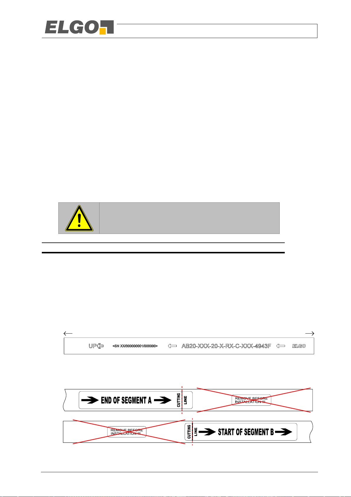
Before mounting, check the correct order of the tape segments (A bottom, B centre, C top) and their
orientation. The printed arrows must point to the head of the shaft.
Fig 16: Correct direction of magnetic tape
At the transition points between two tape segments, disconnect the protective pole at the marked point
before sticking the magnetic tape. The optimum contact pressure is 4 - 5 kg/cm2.
In the case of longer measuring ranges consisting of more than one tape segment, care must be taken
to ensure that the segments are not laterally offset at the transition between the two segments and are
close to each other at the ends as shown in the following figure.
- 33 -

Installation and First Start-Up
NOTE!
Ensure a proper vertical tape mounting.
If the order of the tape segments is wrong, a wrong position will be
read during the transition from one segment to the next and the sensor
will go into the error state.
4 mm
General remarks:
Figure A/B: The sensor surface must be installed parallel to the magnetic tape without twisting
Figure C: The sensor must maintain a lateral offset of 4 mm over the entire measuring distance
Figure D/E: A lateral offset outside this dimension is not permitted and leads to measurement errors,
which in turn entails the request for the safe state.
A B
C
D E
2 … 8
mm
2. Mount the sensor with the plug connection pointing upwards on the cabin.
3. Align the sensor. Use the tape as a reference. First align the sensor in the middle with a lateral offset of
4 mm to the side edge of the magnetic tape (point C in Fig 17).
4. Now set the distance between the tape and the sensor. The maximum reading distance between the
sensor housing and the surface of the magnetic tape must not exceed 8 mm. Make sure that the sensor
head is mounted vertically.
5. Check the correct mounting. Deviations and angular misalignments must be corrected!
Fig 17: Evaluation of the tape alignment to the sensor - Rotation and misalignment of the magnetic tape
- 34 -

Installation and First Start-Up
General remarks:
The sensor scanning surface must be kept parallel to the tape over the entire measuring distance
A twist as shown in the left or right illustration leads to incorrect measurement results, which in
turn entails the request for the safe state.
Fig 18: Evaluation of the magnetic tape to the sensor - inclined mounting of the sensor
6. IMPORTANT: Assembly check!
To prevent damage, the sensor must not rub against the surface of the magnetic tape. However, occasional contact due to movement of the sensor is not critical. Therefore, make an inspection run over the
entire lifting height and check the distances between the belt and the sensor. Also check the underside
of the sensor at some points. If this is slightly inclined – the sensor can be perfectly aligned at the top,
but still come into contact with the magnetic tape at the bottom – the sensor may rub at the surface of
the magnetic tape.
- 35 -

Installation and First Start-Up
Correct
Wrong Wrong
General remarks:
Maximal
erlaubter
Abstand
Vorgeschriebener
Montageabstand
Minimal
erlaubter
Abstand
Minimal
erlaubter
Abstand
Maximal
erlaubter
Abstand
Abstand gleich
wie oben
Maximum
permitted
distance
Specified
mounting distance
Minimum
permitted
distance
Minimum
permitted
distance
Maximum
permitted
distance
Distance identical
to top
Over its entire length the sensor must be kept parallel and within the specified distance to the
magnetic tape
Contact between the magnetic tape and the sensor housing must be avoided, as this leads to
unwanted abrasion.
Fig 19: Evaluation of the vertical alignment of the sensor
7. If the check shows that the tape nevertheless rubs against the sensor with the magnetic side, it can be
assumed that the tape is not mounted on a vertical surface in the shaft.
8. Clean the tape after installation. Use a dry, clean cloth. Start at the head of the shaft and drive all the
way down in inspection mode. Press the cloth lightly onto the magnetic tape.
9. Cleaning should be carried out especially after metal work in the shaft. Metal chips like to stick to the
tape due to the magnetism.
10. Repeat this cleaning procedure before putting the elevator into operation.
- 36 -

Design and Functions
9 Design and Functions
9.1 Sensor Design .................................................................................................. 37
9.2 Operating Modes ............................................................................................. 39
9.2.1 Dual-Channel Operation ................................................................................................. 39
9.2.2 Single-Channel Operation ............................................................................................... 39
9.3 LED Signals ...................................................................................................... 39
9.3.1 Signalling Severe Errors ................................................................................................... 41
9.4 Door Zone Indication ........................................................................................ 42
9.5 Connections and Interfaces ................................................................................ 42
9.5.1 Power Supply ................................................................................................................. 42
9.5.2 Door Zone Indication ...................................................................................................... 42
9.5.3 Pin Assignment ............................................................................................................... 43
9.5.3.1 RS-485 Interface ................................................................................................................. 43
9.5.4 Protocol Descriptions ....................................................................................................... 43
9.5.4.1 RS-485 Interface ................................................................................................................. 43
9.5.5 Presence Detector Magnetic Tape (only semi-guided variant) ................................................ 49
9.1 Sensor Design
The sensor consists of:
Sensor housing with integrated LEDs (for signaling of various status options), fixed connector for power
supply and for communication with the safe evaluation unit.
Guide rail which holds the magnetic tape at a defined distance from the evaluation electronics (only
semi-guided version)
Ground connector to improve EMC characteristics (connection not mandatory)
- 37 -

Design and Functions
Fig. 20: Components of the sensor (semi-guided variant)
Fig. 21: Components of the sensor (unguided variant)
tape guide
connector
earth lug
LED indicator
sensor housing
screw for fixing
the tape guide
LED indicator
connector
earth lug
sensor housing
The electronic part of the sensor is basically done in a two-channel design. For safety reasons the communication interface is operated by both channels together. Each of the two channels contributes their part of the position information transmission. In case of an error, each channel is able to signal the request for transition into
safe state independently from the other channel.
Further information:
Transmission of position information 9.5.4
- 38 -

Design and Functions
Fig. 22: LED signals on the upper side of the sensor
9.2 Operating Modes
The sensor can be operated in two different modes:
Safe dual-channel operation
Non-safe single-channel operation (energy saving mode)
Switching between modes happens automatically, depending on the supply voltage.
9.2.1 Dual-Channel Operation
Usually, the sensor works in dual-channel operation. In this mode, both channels are fully functional and determine the position independently of each other. After determining the position, the position results of the two
channels are compared and then transmitted to the safe evaluation unit via a safe interface. If an internal error
is detected or if the position results of the two channels do not match, the sensor sends a request for transition
into safe state to the evaluation unit. The evaluation unit has to make sure that the safety circuit is opened.
Further information:
Overview of error status and possible errors: 12.6
Protocol description of the safe position information transmission 9.5.4
9.2.2 Single-Channel Operation
In order to keep the door zone indication functioning in case of loss of the regular power supply (24V operating
voltage), the sensor can be operated with an external 12V back-up battery or an emergency power supply. To
maximise the durability of the back-up battery, one channel is switched off. All position comparisons between
the two channels are terminated in such a case and the sensor communicates only the non-safe position result
of one channel to the evaluation unit. If the evaluation unit is still in operation at that time, it can further process
this position information for non safety related functions. The evaluation unit absolutely has to switch into safe
state.
Further information:
Possible additional circuit for automatic switch to single-channel operation 9.5.1
Protocol description of the position information transmission 9.5.4
9.3 LED Signals
The LEDs at the upper side of the sensor (shown in Fig. 22) signal the operating status or possible errors:
PWR A: Supply voltage channel A
PWR B: Supply voltage channel B
RUN: Operating status
ERR: Signalling of an error
TAPE: Magnetic tape status
The LEDs PWR A, PWR B signal the status in a static manner. They are either turned on or off. The LED RUN
flashes, with the frequency depending on the operating status. The LED ERR has three possible states: Off, regular flashing and irregular flashing. The LED TAPE also knows three possible states: off, on and irregular flashing.
- 39 -

Design and Functions
LED
Colour
Status1
Meaning
PWR A
yellow
ON
Supply voltage channel A available
OFF
Supply voltage channel A not available
PWR B
yellow
ON
Supply voltage channel B available
OFF
Supply voltage channel B not available. The sensor head is in the energy saving
mode because of low voltage supply or there is no power supply at all.
RUN
green
Flashing
5 Hz
Safe position data is transmitted via the interface
Flashing
12/3 Hz
The sensor head is operating in single-channel mode. Non-safe position information is transmitted via the interface.
Static
light on
The sensor has been blocked intentionally. Also see: LED ERR.
ERR
red
OFF
No error
Flashing
1 Hz
At least one error has been detected, but it is not classified as a severe error.
Find more information on the problem in the Error Register ( 12.2.3)
The exact cause is transmitted via the interface to the evaluation unit as long as
the sensor is in dual-channel operation ( 9.5.4) In single-channel operation;
no detailed error diagnosis is possible.
Further information on error clearance: 12.6
Flashing
irregular
frequency
The sensor had has blocked itself due to a severe error. The unit should be
replaced. The exact cause is communicated via a flashing code of the LED ERR
( 9.3.1).
TAPE
yellow
ON
Magnetic tape cannot be detected or is damaged
OFF
Magnetic tape is detected
Flashing
irregular
frequency
The sensor had has blocked itself due to a severe error. The unit should be
replaced. The exact cause is communicated via a flashing code of the LED ERR
( 9.3.1).
1
Each state has a meaning regarding whether an error occurred and how serious the error is.
The following table shows what states can be signalized by the five LEDs:
Table 1: Meaning of LED signals
The status in bold define the faultless normal operation
- 40 -

Design and Functions
Flashing
code
Meaning
01h
02h
03h
04h
RAM test failed
05h
ROM test failed
06h
CRC check sum of code memory is not the same in both channels
07h
Stack test failed
08h
Undefined case in a multiple branch
09h
Test of CRC hardware failed
0Ah
Communication test between channels failed
0Ch
CPU test failed
0Dh
0Eh
Defective program sequence
10h
Channel assignment not unambiguous
11h
Position outside the allowed range
12h
Synchronization failed
20h
21h
Timeout during memory test
22h
Error in timer for timeout detection
40h
UART error
41h
42h
Invalid parameter
43h
Undefined exception
44h
45h
46h
Faulty position determination
47h
Parameter outside the allowed range
t [s]
0 2 4 6 8 10 12 14 16 18 20 22
off
on
0 0 0 1 0 0 1 0
LED ERR
restart blink codeillustrated value 12
16
9.3.1 Signalling Severe Errors
If a severe error ( 12.3) occurs, the sensor head is intentionally blocked. All communication via the interface is
shut down. Such errors will be signalled by the LED ERR (channel A) and LED TAPE (channel B) to the user via a
sequence of 8 flashing impulses (short or long). A short flash impulse stands for a zero, a long flash impulse
stands for a one. The first impulse corresponds to the MSB, the last impulse corresponds to the LSB. The sequence is repeated after a 4 second break. You can find an example of such a sequence in Fig. 23.
If such a severe error occurs, the sensor has to be replaced. The flashing sequence codes support ELGO in
finding the exact cause for an error in case of necessary repairs.
Fig. 23: Illustrated example of an LED ERR flashing sequence, signalling a severe error
Table 2: Meaning of flashing codes due to severe errors
- 41 -

Design and Functions
NOTE!
In order to keep the indication of the door zones active for an evacuation during a loss of the regular power supply, an emergency power
supply or a back-up battery is necessary to supply the sensor with energy.
Fig. 24: Possible circuit for supply by emergency battery in case of power failure
regular power supply +24 VDC
emergency battery +12 VDC
power supply sensor
9.4 Door Zone Indication
LIMAX44 RED provides a function to indicate the door zones. This function shows whether an elevator is positioned within the door zone, even during a power failure. The location of the door zones is derived from the
flush positions of the different floors. These positions must be determined during the initial reference journey for
the evaluation unit. The positions of the floor levels are saved permanently and are available even after a power
failure.
The position of the floors must be transmitted from the evaluation unit to the sensor. Also, the evaluation unit
has to signal changes in the position of the floors to the sensor.
After the sensor is switched on, the door zone output is briefly switched to active. This enables a function check
of the downstream indicator lamp.
Further information:
Technical data of output 6.5
Protocol for alignment of floor positions 9.5.4, in the section on floor information under the respec-
tive interface
9.5 Connections and Interfaces
The following chapters will give you detailed information on the connections and interfaces
9.5.1 Power Supply
Normally, LIMAX44 RED is supplied with 24 VDC. In order to guarantee the functioning of the door zone indication for evacuation in case of a power failure, an external 12 V battery can be connected.
Switching between the two supply voltages has to take place outside the sensor and can be realized for example
with the following diode circuit:
The sensor switches automatically between the two operating modes ( 9.2) based on the applied supply voltage.
The pin assignment depends on the connection option and is documented in chapter 9.5.3.
9.5.2 Door Zone Indication
For the indication of the door zones, a PNP-output is integrated in the sensor. It can be directly connected to a
light bulb or an LED for indicating the status.
The output is short-circuit-proof against GND (but not against +24 V) and can be operated with max. 200 mA.
- 42 -

Design and Functions
WARNING!
In order not to jeopardize the safe communication between the sensor
and the evaluation unit, the RS-485 connection has to be realized as a
point-to-point connection. Apart from the sensor and the evaluation
unit, no other devices shall be connected to the bus!
Connection Type
Connection option acc.
to type designation
Drawing
Assignment
Circular plug
M12
A-Coded
M12M
1 +24 VDC
2 0 V
3 RS-485+
4 RS-4855 Output door zone indication
Segment
Length in bits
Content
A
8
Message counter
1
2
3
4
5
A B C D E F
t
bus data
9.5.3 Pin Assignment
9.5.3.1 RS-485 Interface
The internal termination resistor of the RS-485 bus is assembled in all sensors with RS-485 interface, even when
it is not explicitly stated in the interface options ( 7 Type Designation). The bus must be terminated also on the
side of the evaluation unit.
Table 3: Pin Assignment RS-485 Interface
9.5.4 Protocol Descriptions
9.5.4.1 RS-485 Interface
The communication between the sensor and the evaluation unit is bidirectional. The sensor sends the position
information and receives the floor information.
9.5.4.1.1 Interface Parameters
For a correct transmission of the data, the interface in the evaluation unit must be set to the following parameters:
115200 bps
8 data bits
No parity bit
1 stop bit
No flow control
9.5.4.1.2 Structure of a Message
A message consists of six segments and has an overall effective length of 88 bits. It is divided into 11 symbols of
8 bits each. The first three segments A to C are sent by channel A, the other three segments D to F by channel B.
Fig. 25: Structure of a RS-485 message
The different segments carry the information according to the following table. You can find a more detailed
description of the content of the segments in the following chapters. Segments A to D contain the safety-relevant
information.
Table 4: Description of the segments in an RS-485 message
- 43 -

Design and Functions
Segment
Length in bits
Content
B
4
Status bits C 20
Verified position, coarse resolution (1 LSB ≙ 1 mm)
D
32
CRC check sum for segments A to C
E
16
Additional information
F
8
Non-verified, high-resolution position offset (1 LSB ≙ 62.5 µm)
NOTE!
In single-channel operation, channel B is switched off and segments DF are not transmitted. This corresponds to a non-verified position
transmission.
Bit1
Meaning of the signalled value
4
Warning – extrapolated position:
0 = Position was determined normally in both channels
1 = Due to a reading error in one of the channels, the position was extrapolated
5
Signalling faulty tape:
0 = Tape correct
1 = Tape not present or faulty
6
Signalling unauthorized extrapolation:
0 = Extrapolation active
1 = Extrapolation was deactivated because there were too many reading errors. Further operation is
not allowed. ( 12.1)
7
Single-channel operation
0 = Sensor is in dual-channel operation
1 = Due to under voltage, the sensor is in single-channel operation. Caution: only segments A to C
are transmitted!
NOTE!
If the position is extrapolated due to reading errors unusually often, this
might point to an extremely dirty or damaged magnetic tape. In this
case, proceed as is described in chapter 13 Maintenance.
1
9.5.4.1.3 Message Counter
The message counter identifies the correct message sequence and is raised by one with every message. It is
according to this index that the additional information ( 9.5.4.1.7) is attributed.
The range of values for the message counter is from 0 to 255. When the counter has reached the maximum
value, there will be an overflow and with the following message, counting starts again from 0.
9.5.4.1.4 Status Bits
The status bits provide additional information to the position. They always refer to the position with which they
are transmitted.
Table 5: Meaning of the status bits in an RS-485 message
Since the described status bits usually never change, they are dynamised, i.e. they change their status depending
on the message counter. If the LSB of the message counter is set (odd counter value), all four status bits are
inverted bitwise before transmission; if the LSB is cleared (even counter value), the transmitted value matches the
signalled value.
9.5.4.1.5 Position
Please note that the status bits do not require an entire byte for themselves. The bit position stated here corresponds to the
actual position in the second byte of the message.
- 44 -

Design and Functions
Counter
Reading
Content
0
CRC check sum program memory, bits 16 … 31
1
CRC check sum program memory, bits 0 … 15
2
Serial number of sensor, bits 16 … 31
3
Serial number of sensor, bits 0 … 15
4
Error register channel A, bits 16 … 31 ( 12.2.3)
5
Error register channel A, bits 0 … 15 ( 12.2.3)
6
Error register channel B, bits 16 … 31 ( 12.2.3)
7
Error register channel B, bits 0 … 15 ( 12.2.3)
8
Resolution of the floor table. Specifies by how many bits the position (in mm) is shifted to the
right (this value is fixed to 4, which corresponds to a resolution of 16 mm).
9 … 127
Reserved. The transmitted value is always 0.
128 … 191
Statistical information channel A
174
Lowest detected power supply voltage channel A (1 LSB ≙ 67.7 mV)
The position is transmitted in two parts. Segment C contains the verified position, which has to be used in the
evaluation unit for safety functions. This position only counts as verified when the sensor is in dual-channel operation and transmits the correct CRC check sum ( 10.2 Software Requirements). When in single-channel
operation, the second part of the message is missing and the position cannot be sufficiently verified. This is
called a non-verified position or unsafe position data.
The position in this segment has a resolution of 1 mm. In order to reach a higher resolution, the position offset
from segment F can be used. Since this information only provides an insignificantly small contribution to the
overall position, it is not additionally verified. However, it can be used for a better quality of the safety functions,
if this cannot cause dangerous situations.
The use of the high-resolution position for position control by the controller is not restricted.
Segment C is transmitted in the Motorola format.
9.5.4.1.6 CRC Check Sum
For use in safety functions, the position, the message counter and the status bits are verified with a CRC32
check sum. The data may only be used if the CRC check sum is correct ( 10.2 Software Requirements).
The polynomial G(x)=x32+x26+x23+x22+x16+x12+x11+x10+x8+x7+x5+x4+x2+x+1 is used for calculation. This
is the same polynomial that is used in Ethernet.
The data stream D(x)=x31+…+x0 is composed from the segment data as follows:
D(x)=a7+…+a0+b3+…+b0+c19+…+c0, with the bits corresponding to the respective segments:
a7…a0: Segment A (message counter)
b3…b0: Segment B (status bits)
c19…c0: Segment C (coarse-resolution position)
The initialization value for the calculation of the CRC check sum is FFFFFFFFh.
LIMAX44 RED calculates the CRC check sum in reverse bit order, which causes the calculated CRC check sum
to be transmitted backwards. The calculated CRC check sum is inverted bitwise before the transmission. The
transmission is in the Motorola format.
9.5.4.1.7 Additional Information
The additional information in segment E only has an informative character and is meant primarily for finding
errors. The content of this segment varies depending on the value of the message counter ( 9.5.4.1.3 Message Counter). One complete transmission cycle lasts about one second (256 x 4 ms); this is sufficient for the
purely informative use. The additional information is transmitted in the Motorola format.
Table 6 describes the content of the additional information depending on the value of the message counter.
Table 6: Additional information as a function of the value of the message counter
- 45 -

Design and Functions
Counter
Reading
Content
175
Highest detected power supply voltage channel A (1 LSB ≙ 67.7 mV)
180
Errors set in error register channel A since restart, bits 16 … 31 ( 12.2.3)
181
Errors set in error register channel A since restart, bits 0 … 15 ( 12.2.3)
182
Operating time (seconds since restart) channel A bits 16 … 31
183
Operating time (seconds since restart) channel A bits 0 … 15
192 … 255
Statistical information channel B
238
Lowest detected power supply voltage channel B (1 LSB ≙ 67.7 mV)
239
Highest detected power supply voltage channel B (1 LSB ≙ 67.7 mV)
244
Errors set in error register channel B since restart, bits 16 … 31 ( 12.2.3)
245
Errors set in error register channel B since restart, bits 0 … 15 ( 12.2.3)
246
Operating time (seconds since restart) channel B Bits 16 … 31
247
Operating time (seconds since restart) channel B Bits 0 … 15
NOTE!
The operating time is transmitted in two messages, separated into highword and low-word. If the overflow in low-word (carry-over to highword) happens between the transmission from low-word to high-word,
it is possible that the combined time temporarily displays an inconsistent value.
- 46 -

Design and Functions
Counter
reading
Content
0
Number of floors
1
Size of door zone (0 … 1020 mm; 1 LSB ≙ 4 mm)
2
LSB of the flush position first floor (1 LSB ≙ 16 mm)
3
MSB of the flush position first floor (1 LSB ≙ 16 mm)
…
…
255
MSB of the flush position 127th floor (1 LSB ≙ 16 mm)
9.5.4.1.8 Floor Information
In order for LIMAX44 RED to operate the door zone indication, the evaluation unit has to transmit the floor information to the sensor. In the interval between two telegrams the evaluation unit has time for this. (
9.5.4.1.10 Bus Timing). LIMAX44 RED assigns the received information in relation to the message counter (
9.5.4.1.3) of the message that was just sent.
Table 7: Floor information as a function of the value of message counter
This data is for the transmission of the floor image, so that LIMAX44 RED can generate the door zone signal as
return motion information. For this purpose, the resolution of 16 mm is sufficient.
If necessary, LIMAX44 RED will update the stored floor image based on the received data. In order to avoid
non-recurring transmission errors having an influence on the floor image, the floor table is only changed when
the information is transmitted a second time, i.e. is confirmed. Depending on the value of the message counter,
it therefore can take up to two seconds before LIMAX44 RED takes over the new floor information and safes it
permanently.
Flush positions of floors with a floor number higher than the number of floors are ignored.
LIMAX44 RED only evaluates the floor information in dual-channel operation ( 9.2.1) since a valid test drive
requires that both channels are activated anyway.
9.5.4.1.9 Request for Transition into Safe State
If one of the two channels detects that something is out of order by comparing the position with the other channel or during the periodic self-diagnostics, a request for transition into safe state is transmitted to the evaluation
unit.
Both channels can request the safe state of the evaluation unit independently of one another. Channel A does
this by setting the position in Segment C to 0. Channel B does this by inverting the CRC check sum.
The frequency of the request for safe state depends on how long the error has been present. There is a distinction between short-term and long-term interference.
In case of temporary or short-term interference ( 12.2.1), the request for transition into safe state is transmitted
with every fourth message (Fig. 26, top). In between the requests, the position is still transmitted to the evaluation unit.
In certain cases it is possible that channel B detects interference while channel A is already sending. In this case,
channel B sends the request for safe state one transmission period earlier than channel A (Fig. 26, bottom). This
can lead to two requests in a row for safe state. The evaluation unit has to tolerate this effect.
In case of long-term interference ( 12.2.2), the request for transition into safe state is transmitted with every
message (Fig. 26, centre). A criterion for permanent deactivation is met when the request for transition into safe
state is sent three times in a row.
In case of interference in the position determination ( 12.1), the status of short-term interference is not applicable. With these errors, position 0 or the inverted CRC check sum respectively are sent with every message.
- 47 -

Design and Functions
t
| | | | | | | | | | | | | | | | | | | | | | | | | |
|
t
| | | | | | | | | | | | | | | | | | | | | | | | | |
|
t
| | | | | | | | | | | | | | | | | | | | | | | | | |
|
Valid position data
Request for safe state by channel A (position 0)
Request for safe state by channel B (inverted CRC check sum)
Request for safe state by both channels (position 0 and inverted CRC check sum)
Error occurs, request for safe state is sent immediately after detection.
If the error is present for a certain amount of time, the request for transition into safe state is transmitted
with every message.
Error detection channel B
Channel A signals error with the next message
NOTE!
The gradual request for transition into safe state allows the evaluation
unit to react more smoothly in case of a temporary interference which
may be the result of a temporary, very strong electromagnetic interference. For example, the evaluation unit can close the safety circuit autonomously after a temporary interference has disappeared, while it
makes sense to set an error in case of a persisting interference.
The described behaviour is just an example. The actual behaviour depends on the evaluation unit and has to be defined and evaluated
during its development.
Fig. 26: Example of a request of the evaluation unit for transition into safe state. Temporary signalling (top), transition from
temporary to permanent signalling (centre), and staggered signalling of the two channels (bottom).
Further information:
Requirements for evaluation unit: 10.2
Non-severe interference: 12.2
9.5.4.1.10 Bus Timing
LIMAX44 RED divides the transmitted messages into two packets. The first data packet, consisting of segments A
to C ( 9.5.4.1.2 Structure of a Message), is sent by channel A; the second data packet, consisting of segments
D to F, is transmitted by channel B. After the end of this transmission the evaluation unit has time to put the floor
information to the bus byte wise. Since the sensor is not directly ready to receive data after release of the RS-485
bus, it is imperative that the time tP (see Fig. 27 and Table 8) is allowed to elapse before the evaluation unit puts
data on the bus.
The interface parameters for the structure of the symbols are described in 9.5.4.1.1.
When changing from dual-channel operation to single-channel operation and back, the message-sendinginterval is shortened/lengthened by the time tC once because there are no internal comparisons in singlechannel operation.
- 48 -

Design and Functions
Symbol
Description
Min
Typ
Max
Unit
tM
Message transmission interval
4
ms
tA
Transmission segment A … C by channel A
347 µs
tB
Transmission segment D … F by channel B
608 µs
tE
Transmission floor information from evaluation unit
87 µs
tP
Pause time until the evaluation can put the floor information on the bus1.
150
(at 70°C)
µs
tC
Time shift due to omitted comparison between the
channels in single-channel mode.
276 µs
tS
Lag between take-over of the RS-485 bus and start bit
of the first data bit channel A.
2 12
µs
tH
Time to hand-over the bus from channel A to channel B
(from stop bit of last symbol of channel A until start bit
of first symbol of channel B).
55 75
µs
tR
Delay bus release (from stop bit of the last symbol until
bus driver is switched to high impedance).
7 9
µs
1
Dual-channel operation:
Single-channel operation:
LIMAX44 RED is driving the bus Evaluation unit is driving the bus
t
P
t
B E A BA
t
t
M
AA
t
C
t
E
t
A
t
B
A B
t
S
t
H
t
t
R
start bit stop bitbus driver on
bus driver off
Fig. 27 shows an overview of the bidirectional bus timing. The details, especially the time of the bus take-over
and release, are shown in Fig. 28. A more detailed description of the time symbols and the specific limit values
are listed in Table 8.
Fig. 27: Overview of the bus timing. A = transmission data channel A; B = transmission data channel B; E = floor information of evaluation unit.
Fig. 28: Bus Timing Details (not to scale)
Table 8: Description of the timing symbols (at 25°C, if not stated otherwise)
9.5.5 Presence Detector Magnetic Tape (only semi-guided variant)
The presence detector serves to assure that the magnetic tape is in the correct position and stays there. Using
the appropriate mechanics it is possible to detect the following faults:
The evaluation unit may only occupy the RS-485 bus after tP has elapsed because LIMAX44 RED cannot process the infor-
mation earlier.
- 49 -

Design and Functions
Tape rupture above the cabin / above the sensor
Tape rupture below the cabin / below the sensor
Loosening of the tape fixation in the shaft head
Magnetic tape getting stuck in the sensor
In order for the sensor to fulfil its task, it has to be regularly serviced and tested. Further information: 13
Maintenance.
- 50 -

Requirements for Evaluation Unit
NOTE!
Even when working with two synchronized processors, there is no guarantee that the data received from the sensor regarding channel 1 and
channel 2 are always 100 % consistent. Due to slight delay differences,
it is possible that for example channel 1 has already received a new
data packet while channel 2 is still working with the data from the previous packet. The software of the evaluation unit should take this effect
into account in order to avoid availability problems.
1
10 Requirements for Evaluation Unit
10.1 Hardware Requirements
The design and the structure of the input circuit of the evaluation unit are generally subject to the specifications
of the evaluation unit. When working with a multi-channel structure, the data has to be transmitted to all channels.
If all errors stated in 10.2 can be detected, the bus drivers (transceiver) and protective circuit may also be realised in a single-channel structure.
10.2 Software Requirements
10.2.1 Requirements for RS-485 Interface
The evaluation unit has to perform at least the following checks on the received data:
The message counter has to match the expected value.
The CRC check sum for segments A to C ( 9.5.4.1.2) calculated in the evaluation unit has to match
the CRC check sum received in segment D or its value that has been inverted bitwise (request for transition into safe state by channel B)
The timing has to be maintained. Two consecutive message packets have to have an interval of 4ms
with a max. tolerance of ±20%. This implicitly includes detection of a time-out when the sensor is not
transmitting anymore.
The number of the received bytes has to be exactly 11. In single-channel operation ( 9.2.2), the sen-
sor will not send a verified position. Such a data packet may not be used for safety functions.
Errors in the transmission of symbols (framing errors) have to be detected.
The position has to be valid. The position 0 is the request for transition into safe state by channel A.
If an error is detected in one of the points stated above after suitable filtering1, the evaluation unit has to assume
the safe state.
10.2.2 General Requirements
The following measures are not compulsory but recommended:
Repeated check for implausible jumps
Exchange of the received positions between the channels and comparison with the position of the other
channels. If this comparison is not performed, at least the process factors or states derived from the position information must be compared with each other.
The type of filtering is not specified and depends on the design of the evaluation unit. The filtering parameters are basically
determined based on the reaction time for opening the safety circuit.
- 51 -

Accessories
LIMAX S-RMS-H
LIMAX S-RMS-WH
Order designation
Description
LIMAX S-RMS-H
Magnetic tape installation kit with tape detection and tension spring for high rise
elevators
LIMAX S-RMS-WH
Magnetic tape installation kit with tape detection and tension weight for high rise
elevators
11 Accessories
11.1 Mounting Kit Magnetic Tape (only semi-guided variant)
ELGO offers the following mounting kits for fixing the magnetic tape.
- 52 -

Accessories
LIMAX3 MW SET
Order designation
Description
LIMAX3 MW SET
Mounting angle for LIMAX33/LIMAX44 RED with four each of screws, nuts and
washers for mounting the sensor
LIMAX4R Service Set
Order designation
Description
LIMAX4R Service Set
Spare part set consisting of each four guide rails, screws, nuts and eight washers
Order designation
Description
CABLE-LIMAX4R-M12MS-M12FS-05.0
Connection cable 5 m, 5-pin, M12 (1:1 extension cable)
11.2 Mounting Aid Sensor
11.3 Spare Material Sensor
11.4 Connection Cable
- 53 -

Disturbances
12 Disturbances
This chapter describes possible causes for disturbances and measures for their removal. In case of increased
disturbances, please follow the measures for fault clearance in chapter 12.5.
In case of disturbances that cannot be eliminated by following the advice and the fault clearance measures given here, please contact the manufacturer (see second page).
12.1 Error in Position Determination
If no tape is present or if the magnetic information on the tape cannot be read unambiguously and consistently,
the sensor switches into error mode. No valid position information is transmitted anymore; instead, a request for
transition into safe state is transmitted and the corresponding status information is set in the status bits.
This state is not reset even if the tape is detected again later on and the position sequence is correct again. This
mode is only reset after a complete re-start (incl. battery voltage).
Further information:
Requirements specific to the protocol for transition into safe state: 9.5.4
12.2 Non-severe Errors
If an error is detected that does not jeopardize the internal programme sequence, the error is transmitted to the
evaluation unit via external interface. The transmission happens in two steps.
12.2.1 Step 1 – Short-Term Interference
During the first step it is assumed that the interference is only a short-term one. In this stage, the request for
transition into safe state is transmitted via external interface. The type of signalling is described in the chapter
Request for Transition into Safe State ( 9.5.4) of the interface in question. In order not to lengthen the reaction
time, the request is first sent immediately after the error occurred.
12.2.2 Step 2 – Long-Term Interference
If the error is still present after 15 seconds, it is safe to assume that there is a serious interference whose causes
should be checked and evaluated by an expert. In this case, the request for transition into safe state is transmitted permanently. This type of error signalling requests the evaluation unit to sustain the safe state until it has
been analyzed and if necessary acknowledged by an expert.
If the error disappears again, the sensor will again begin to send valid position data, no matter if it was a longterm or a short-term interference.
- 54 -

Disturbances
Bit
Problem
Error requires safe
state
0
Overvoltage or undervoltage in general
Yes
1 … 6
Error in voltage monitoring
Yes
7
Error position interpolation
Yes
8 … 12
Internal communication error
Yes
13 … 14
Synchronisation error
Yes
15
EEPROM error
No1
16
Not used
-
17
Comparing of position between the two channels failed
Yes
18
Communication test failed
Yes
19
Extrapolation not allowed anymore. Too many position jumps occurred
Yes
20
Timeout in the non-safety-relevant processing
No
21
Overvoltage 24V
Yes
22
Undervoltage 24V
Yes2
23 … 31
Not used
-
1
2
12.2.3 Error Register
Each of the two sensor channels contains an error register that simplifies the error search. The content of the
error register is transmitted outside via the interface ( 9.5.4 Protocol Descriptions).
Table 9: Content Error Register
12.3 Severe Errors
If one channel detects a severe fault in the processor system (memory error, CPU-error, no communication with
the other channel), its firmware goes into a separate emergency loop and the processors are therefore purposefully blocked. The external interface is not served anymore in this case. This mode is never reset if a voltage is
applied, no matter if normal or battery supply.
There is one exception for channel A to the reaction described above: when there is no communication with the
other channel and the normal supply voltage has a strong undervoltage and therefore channel A is in singlechannel operation. This means that channel B is deliberately switched off ( 9.2.2 Single-Channel Operation).
Under this condition, channel A continues to send its positions and sets the relevant status bit (section Status Bits
in the chapter of the relevant interface 9.5.4). When the voltage returns and all error detection measures
operate in their entirety in both channels, LIMAX44 RED returns to normal operation ( 9.2.1).
12.4 Informative Errors (not Safety-Relevant)
The two chapters 12.2 and 12.3 mainly treated errors in the safety-relevant processing which require the transition into safe state; either explicitly by sending the request for transition into safe state or implicitly due to missing
messages which cause a timeout in the evaluation unit.
In order to avoid non-safety-relevant operational elements influencing this behaviour, some information of a
purely informative character are exempted from the request for transition into safe state. Those errors can only
be identified over the error register ( 12.2.3. Informative errors are also signalled via the error LED. Namely
these are errors in the EEPROM and timeout in the non-safety-relevant processing.
The EEPROM only contains the non-safety-relevant floor table for the indication of the door zones.
An undervoltage of the 24 V implicitly requests a transition into the safe state because in this case the second channel is
switched off in order to save energy and only a non-safe position is transmitted.
- 55 -

Disturbances
NOTE!
As long as there is “only” an informative error the sensor still transmits
valid position data. However, it is possible that the door zone indication is not working as desired. The sensor should be replaced.
CAUTION!
The device, the connection line and the signal cable must not be installed next to sources of interference that emit strong inductive or capacitive interference or strong electrostatic fields.
External perturbations can be avoided thorough suitable cable routing.
The screen of the signal output cable should only be connected to the
following circuit on one side. The screens should not be grounded on
both sides. Signal cables always have to be routed separately from the
load power line. A safety distance of at least 0.5 m has to be kept from
inductive and capacitive sources of interference such as contactors,
relays, motors, switching power supplies, clocked controllers etc.!
If interferences occur in spite of all the items stated above being observed, please proceed as follows:
1. Installation of RC-circuits via contactor coils of AC-contactors
(e.g. 0.1 µF / 100 Ω)
2. Installation of recovery diodes via DC-inductors
3. Installation of RC-circuits via the different motor phases (in the
terminal box of the motor)
4. Do not connect protective earth and ground
5. Connect a mains filter ahead of the external power pack
6. Connect the ground connector to ground
12.5 Fault Clearance
- 56 -

Disturbances
Pos Problem
Possible cause
Necessary action
(1) The sensor does not transmit
position data
The sensor is not supplied with energy
Proceed with pos (7)
A severe error occurred. The LED
ERR
reports the
error through a blinking code ( 9.3.1).
Replace the sensor.
(2) The sensor does not send safe
positions/ incomplete messages
see pos (5)
See pos (5)
(3) The sensor is constantly sending
position 0
There is no magnetic tape or it is strongly polluted
or damaged.
Check the magnetic tape.
The sensor has detected an interference
Read out the error register of the two channels and
proceed as described in 12.6.2 under the corresponding bit
(4) None of the LED light up
The sensor is not supplied with energy
Proceed with pos (7)
(5) The LED
PWR B
doesn’t light up
There is an undervoltage and the sensor therefore
is in single-channel operation.
Check the regular power supply (see also 9.5.1)
(6) Only the LEDs
PWR A
and
PWR B
light up
The sensor is operated without the magnetic tape,
which means that the initialization cannot be
completed.
Check the magnetic tape.
A severe error occured in the early phase of the
initialization.
Replace the sensor.
(7) The sensor is not supplied with
energy
Blackout of the supply or interruption of the
supply line
Check if the energy supply is working correctly and
the sensor is correctly connected to it.
The energy supply is not connected correctly
Check if the supply line O V and +24 V are connected with the correct pole orientation. Exchange both
connections if necessary. If the problem still remains,
replace the sensor.
Bit
Problem
Possible cause
Necessary action
0
General over- or undervoltage
Overvoltage of the external supply
Check the supply and exchange if necessary.
Defective hardware
Replace the sensor.
1 … 6
Error in the monitoring of
the voltage.
Defective hardware
Replace the sensor.
7
Interpolation error
Defective hardware
Replace the sensor.
8 … 12
Internal communication
error
Massive electromagnetic interference
Perform the fault clearance according to 12.5 if
necessary
Defective hardware
Replace the sensor.
13
Synchronization error
when switching between
single and dual channel
operation
Strong electromagnetic interference
Perform the fault clearance according to 12.5 if
necessary
Defective hardware
Replace the sensor.
14
Synchronization error
Strong electromagnetic interference
Perform the fault clearance according to 12.5 if
12.6 Possible Errors and their Clearance
12.6.1 General interferences
The following table shows possible interferences and their clearance.
Table 10: General interference clearance
12.6.2 Non-severe Errors
The following table refers to the bits in the error register. ( 12.2.3).
Table 11: Non-severe errors and their clearance
- 57 -

Disturbances
Bit
Problem
Possible cause
Necessary action
necessary
Defective hardware
Replace the sensor.
15
Memory error EEPROM
Defective hardware
Replace the sensor.
16
not used
Error while writing the EEPROM
Switch the sensor off and on again.
17
Failure of the comparison
of the position between the
two channels
Strong electromagnetic interference
Perform the fault clearance according to 12.5 if
necessary
Defective hardware
Replace the sensor.
Strongly polluted magnetic tape
Clean the magnetic tape ( 13 Maintenance)
Damaged magnetic tape
Replace the magnetic tape. Attention: after replacement, a reference journey has to be performed!
18
Failure of the communication test
Strong electromagnetic interference
Perform the fault clearance according to 12.5 if
necessary
Defective hardware
Replace the sensor.
19
Inadmissible extrapolation.
Too many position jumps
occurred.
Strongly polluted magnetic tape
Clean the magnetic tape ( 13 Maintenance)
Defective hardware
Replace the sensor.
Damaged magnetic tape
Replace the magnetic tape. Attention: after replacement, a reference journey has to be performed!
20
Timeout in non safety
relevant processing
Defective hardware
Replace the sensor.
21
Overvoltage 24 V
Overvoltage of the external supply
Check the power supply.
Defective hardware
Replace the sensor.
22
Undervoltage 24 V
Undervoltage of the external supply
Check the supply. See pos. (5) in 12.6.1
Defective hardware
Replace the sensor.
23 … 31
Not used
12.6.3 Severe Errors
A severe error ( 12.3) is signalled with the blinking of the LED ERR ( 9.3.1). If such an error occurs, the sensor will be set out of service. The communication is stopped completely. The sensor needs to be replaced in
such a case.
- 58 -

Disturbances
WARNING!
Danger of injury through non-conventional fault clearance!
Non-conventional fault clearance can lead to severe injuries and damage of property.
Therefore:
Any work to clear the faults may only be performed by suffi-
ciently qualified staff
Arrange enough space before starting the works
Make sure that the mounting area is clean and tidy. Loose
components and tools are sources of accidents.
If components need to be replaced:
Pay attention to a correct installation of the spare parts.
Reinstall all the fixing elements properly
Before turning on the device, ensure that all covers and safety
equipment is installed correctly and functions properly
12.7 Re-start after Fault Clearance
After the fault clearance:
1. Reset the emergency stop mechanism if necessary
2. Reset the error report at the super-ordinate system if necessary.
3. Ensure that there are no persons in the danger area.
4. Follow the instructions from chapter 8.
- 59 -

Maintenance
WARNING!
Danger through non-conventional maintenance!
Non-conventional maintenance can lead to severe injuries and damage of property.
Therefore:
Maintenance works may only be completed by staff that has been authorized and trained by the operator.
WARNING!
The device can only be cleaned with a damp cloth, do not use aggressive cleanser!
13 Maintenance
The LIMAX44 RED shaft information system requires minimal maintenance.
The maintenance of the LIMAX44 RED should be done in the course of the regular servicing of the elevator. The
maintenance work consists of the following:
Optical inspection of the magnetic tape. Pay attention to wear and other mechanical damages.
Small mechanical damages (scratches, dents or even small chips) mostly don’t interfere with the measur-
ing. A heavily damaged tape, however, is much more sensitive for further abrasion when incorrectly
guided.
Clean the tape after the mounting. Use a clean and dry cloth. Start at the shaft head and go down the
complete height with inspection travel pulling the magnet tape through the cloth with a slight pressure.
Additional points to check for the semi-guided variant:
Optical inspection of the position of the tape in the sensor guiding rail. Worn-off material on the magnet-
ic side indicates that the tape is guided incorrectly. Check for proper guiding of the tape along the complete lifting height with an inspection travel. If necessary correct the alignment following the criteria from
the chapter Installation and First Start-Up starting on page 23.
Check for proper tension of the tape. Since the tape has been mounted with a spring, the tension can
decrease over time. If necessary re-adjust the tension.
You can find details on the correct tension of the magnetic tape in the mounting instructions for the magnetic tape ( 2.4).
Optical inspection of the plastic guiding. Clean the guiding and remove dirt and other material. The
plastic guiding is a wear part. Replace if necessary.
Test the functioning of the magnetic tape presence detector as described under point 15 in the installa-
tion procedure ( 8.6).
14 Cleaning
- 60 -

Notes:
- 61 -

Notes:
- 62 -

Index
15 Index
Abbreviations .................................................... 5
Accessories ..................................................... 52
Accident prevention regulations........................... 5
Available versions ............................................ 21
Cable ................................. See Connection cable
Causes of risk .................................................... 8
Cleaning ......................................................... 60
Connection Cable ........................................... 53
Connections .................................................... 42
Conventional use ............................................... 9
Demounting ...................................................... 7
Device number ................................................ 14
Dimensions ..................................................... 16
Disposal............................................................ 7
Disturbances ................................................... 54
Door zone indication ........................................ 42
Electric. specification .................................... 42
Dual-channel operation ................................... 39
Energy saving mode ... See Single-channel operation
Error
Informative .................................................. 55
Non-severe .................................................. 54
Severe ......................................................... 55
Error signalling ................................................ 41
Evaluation unit, safe ........................................... 5
Explanation of symbols ....................................... 6
Fault clearance .................................... 56, 57, 59
First start-up .................................................... 22
Fuse ......................................................... 14, 15
Identification ................................................... 14
Installation ...................................................... 22
Interfaces ........................................................ 42
Interference
Long-term .................................................... 54
Position determination .................................. 54
Short-term ................................................... 54
LED signals ..................................................... 39
Interference.................................................. 57
Magnetic tape
Mounting ..................................................... 23
Mounting kit ................................................ 52
Structure ...................................................... 19
Technical data ............................................. 19
Maintenance ................................................... 60
Mounting
Hints ........................................................... 23
Installation procedure ................................... 29
Magnetic tape .............................................. 23
Sensor ........................................................ 27
Mounting aid sensor ........................................ 53
Non-verified position ................................. 44, 45
Normal operation ....... See Dual-channel operation
Operating area ............................................... 22
Operating mode
Dual-channel operation................................ 39
Single-channel operation .............................. 39
Operating modes ............................................ 39
Operational safety ............................................. 5
Order reference .............................................. 14
Packaging material .......................................... 10
Power supply ................................................... 42
Product features .............................................. 11
Protection against contact ................................ 22
Protective equipment ......................................... 8
Requirements for Evaluation Unit ...................... 51
RoHS Conformity ............................................... 7
RS-485 Interface
Bus timing ................................................... 48
Interface Parameters .................................... 43
Pin assignment ............................................ 43
Protocol description ..................................... 43
Structure of a message ................................. 43
Safe state .......................................................... 5
Safety ........................................................... 5, 8
Safety instructions .............................................. 5
Safety Parameters ............................................ 14
Safety rules ....................................................... 5
Scope of operation .......................................... 12
Sensor
Design ........................................................ 37
Mounting .................................................... 27
Mounting aid ............................................... 53
Spare material ............................................. 53
Technical data ............................................. 18
Single-channel operation ................................. 39
Spare material sensor ...................................... 53
Start-up .......................................................... 22
Statement of warranties ...................................... 7
Storage .......................................................... 10
Terms ............................................................... 5
Transport ........................................................ 10
Transport damage ........................................... 10
Type designation ....................................... 14, 21
Unsafe position data ........................................ 45
Verified position .......................................... 5, 45
- 63 -

Document- No.:
D-103836 / Rev. 0
Document- Name :
LIMAX44RED-02-MA-E_23-19
Subject to change - © 2019
ELGO Batscale AG
EL G O Batscale AG
F ö h r e n w e g 2 0 , F L - 9 4 9 6 B a l z e r s
Fon.:+423 (0) 380 02 22, Fax.:+423 (0) 380 02 24
Inter net : ww w.el go. li, Mail: in fo@ elg o.li
Me as uri n g | Pos iti o ni n g | C on t rol
- 64 -
 Loading...