

Operating Manual
SERIES EMAX / EMAL
Magnetic Absolute Linear Encoder with 10 µm resolution
Absolute encoder with 10 µm resolution
No referencing required (changes of position
are also recognized in the de-energized state)
Wear free and contactless measurement
Measuring length up to 10 m (EMAX) resp. 20 m (EMAL)
Too large distances between sensor and magnetic tape
are automatically detected and signalized by an LED
Sensor with fixed cable outlet or optionally with
M9 round connector on sensor housing
Additional incremental or sine-cosine signals for
dynamic movement control available
Available interfaces: SSI, CANopen, RS422, RS232
New: IO-Link acc. to IEC 61131-9
799000616 / Rev. 14/ 2019-01-17
Translation of the original operating manual

- 2 -
Publisher
ELGO Electronic GmbH & Co. KG
Carl-Benz-Str. 1
D-78239 Rielasingen-Worblingen
Technical Support
+49 (0) 7731 9339 – 0
+49 (0) 7731 2 13 11
info@elgo.de
Document- No.
799000616
Document- Name
EMAX-EMAL-00-MA-E_03-19
Document- Revision
Rev. 14
Issue Date
2019-01-17
Copyright
© 2019, ELGO Electronic GmbH & Co. KG

Contents
- 3 -
1 Contents
1 Contents ............................................................................................. 3
2 List of Figures: .................................................................................... 5
3 List of Tables: ..................................................................................... 5
4 General, Safety, Transport and Storage ........................................... 6
4.1 Information Operating Manual ............................................................................. 6
4.2 Explanation of Symbols ........................................................................................ 6
4.3 Statement of Warranties ....................................................................................... 7
4.4 Demounting and Disposal .................................................................................... 7
4.5 General Causes of Risk ........................................................................................ 7
4.6 Personal Protective Equipment ............................................................................... 7
4.7 Conventional Use ............................................................................................... 8
4.8 Safety Instructions for Transport, Unpacking and Loading .......................................... 8
4.9 Handling of Packaging Material ............................................................................ 8
4.10 Inspection of Transport ........................................................................................ 8
4.11 Storage ............................................................................................................. 8
5 Product Features ................................................................................ 9
5.1 Functional principle ............................................................................................. 9
6 Technical Data ................................................................................. 10
6.1 Identification .................................................................................................... 10
6.2 Dimensions Sensor Housing with Cable Outlet ...................................................... 10
6.3 Dimensions Sensor Housing with M9 round connector ............................................ 10
6.4 Dimensions Guide Carriage FW2080 .................................................................. 11
6.5 Technical Data Sensor ....................................................................................... 12
6.6 Technical Data Magnetic Tape ............................................................................ 13
7 Installation and First Start-Up ......................................................... 14
7.1 Operating Area ................................................................................................ 14
7.2 Installation of the Magnetic Tape ......................................................................... 15
7.3 Installation of the Sensor .................................................................................... 18
7.4 Offset Calibration ............................................................................................. 19
8 Interfaces ......................................................................................... 20
8.1 Interface SSI (option SB0 and SG0) ...................................................................... 20
8.2 Interface CANopen (option CA0) ......................................................................... 21
8.3 CAN BASIC ELGO (Option CN0) ........................................................................ 22
8.4 Termination Resistor .......................................................................................... 23
8.5 Interface RS422 (Option 420) & RS232 (Option 230) ............................................. 24
8.6 RS422 Addressable Version (Option A20) ............................................................. 25
8.7 Connection to a RS422 Master ........................................................................... 27
8.8 IO-Link Interface ............................................................................................... 28

Contents
- 4 -
9 Optional Incremental Output .......................................................... 29
9.1 Incremental A/B Signals (TTL / HTL) ..................................................................... 29
9.2 Sine/Cosine Incremental Signals (Option SC50) .................................................... 29
10 Pin Assignment ................................................................................ 30
10.1 Connections of Housing with fixed Cable Outlet .................................................... 30
10.2 Connections of Housing with M9 Round Connector ................................................ 36
11 Disturbances, Maintenance, Cleaning ............................................. 37
11.1 Fault Clearance ................................................................................................ 37
11.2 Re-start after Fault Clearance .............................................................................. 37
11.3 Maintenance .................................................................................................... 37
11.4 Cleaning ......................................................................................................... 37
12 Type Designation ............................................................................. 38
12.1 Example of available Variants ............................................................................. 39
12.2 Accessories ...................................................................................................... 39
13 Index ................................................................................................ 43

Contents
- 5 -
2 List of Figures:
Figure 1: Coding of the magnetic tape ....................................................................................................... 9
Figure 2: Dimensions of sensor with cable outlet ....................................................................................... 10
Figure 3: Dimensions of sensor with M9 round connector .......................................................................... 10
Figure 4: Dimensions of guide carriage FW2080 ...................................................................................... 11
Figure 5: Components of the magnetic tape ............................................................................................. 15
Figure 6: Handling ................................................................................................................................. 16
Figure 7: Tolerances ............................................................................................................................... 18
Figure 8: Mounting direction on magnetic tape ......................................................................................... 19
Figure 9: SSI - reading the data ............................................................................................................... 20
Figure 10: SSI - Gray / binary switchover ................................................................................................. 20
Figure 11: Bit rate and CAN identifier settings ........................................................................................... 21
Figure 12: Bit rate / address (option CN0) ................................................................................................ 22
Figure 13: Termination resistor ON / OFF ................................................................................................ 23
Figure 14: Set options on top of the housing ............................................................................................. 25
Figure 15: Connection to a RS422 Master ................................................................................................ 27
Figure 17: A/B - Inkrementalsignale (TTL / HTL) ........................................................................................ 29
Figure 18: Sine – Cosine Incremental Signals ............................................................................................ 29
3 List of Tables:
Table 1: Mounting tolerances .................................................................................................................. 18
Table 2: Bit rate and CAN-Identifier with option CA0 ................................................................................. 21
Table 3: Identifier Option CN0 ................................................................................................................ 22
Table 4: Bit rate and address settings (option CN0) .................................................................................. 22
Table 5: Bit rate RS422 (option420) and RS232 (option 230) ..................................................................... 24
Table 6: Addressable RS422 Option A20 ................................................................................................. 25
Table 7: Error messages of an addressable EMAX / EMAL .......................................................................... 27
Table 8: Characteristics values for option SC50 ........................................................................................ 29
Table 9: Connections of SSI interface cable 1 ........................................................................................... 30
Table 10: Connections of SSI interface cable 2 ......................................................................................... 30
Table 11: Connections of SSI interface with option M8F0, 8-pin M16 round connector ................................ 30
Table 12: Connections of SSI interface with option MCM0, 12-pin M16 round connector ............................ 31
Table 13: Connections of SSI interface with option D9M0, 9-pin D-SUB connector ...................................... 31
Table 14: Connections of SSI interface Option M8M0, 8-pin M16 round connector ..................................... 31
Table 15: Connections of CANopen interface (open cable ends) ................................................................ 32
Table 16: Connections of CANopen interface with option D9M, 9-pin D-SUB connector .............................. 32
Table 17: Connections of RS422 interface (open cable ends) ..................................................................... 33
Table 18: Connections of RS422 interface with option D9M0, 9-pin D-SUB connector ................................. 33
Table 19: Connection of RS422 interface option D9M5, 9-pin D-SUB connector ......................................... 33
Table 20: Connections of RS422 interface option M8M0, 8 pin M16 round connector ................................. 34
Table 21: Connections of RS232 interface (open cable ends) ..................................................................... 34
Table 22: Connections of RS232 interface with option D9M0, 9-pin D-SUB connector ................................. 34
Table 23: Connections - cable outlet with 4-pin. M12 round connector ...................................................... 35
Table 24: Connections - open cable ends (standard) ................................................................................. 35
Table 25: Connections - 12-pin M12 round connector (RCM0) .................................................................. 35
Table 23: Connections of the 7-pin M9 round connector (male) ................................................................. 36
Table 24: Connections when using the DKA cable with open cable ends ..................................................... 36
Table 25: Connections IO-Link without cable / Table 26: Connections IO-Link with DKA cable .................... 36
Table 27: Example of available variants .................................................................................................... 39
Table 28: Accessories ............................................................................................................................. 39

General, Safety, Transport and Storage
- 6 -
DANGER!
This symbol in connection with the signal word “Danger” indicates an immediate danger for the life and health of
persons. Failure to heed these instructions can result in serious damage to health and even fatal injury.
WARNING!
This symbol in connection with the word „Warning” means a possibly impending danger for the life and health of
persons. Failure to heed these instructions can result in serious damage to health and even fatal injury.
CAUTION!
This symbol in connection with the signal word “Caution” indicates a possibly dangerous situation. Failure to heed
these instructions can lead to minor injuries or damage of property.
DANGER!
This symbol in connection with the signal word “Danger” indicates an immediate danger for the life and health of
persons due to voltage.
Failure to heed these instructions can result in serious damage to health and even fatal injury. The operations may
only be carried out by a professional electrician.
NOTE!
…points out useful tips and recommendations as well as information for an efficient and trouble-free operation.
4 General, Safety, Transport and Storage
4.1 Information Operating Manual
This manual contains important information regarding the handling of the device. For your own safety and operational safety, please observe all safety warnings and instructions. Precondition for safe operation is the compliance with the specified safety and handling instructions. Moreover, the existing local accident prevention regulations and the general safety rules at the site of operation have to be observed.
Please read the operating manual carefully before starting to work with the device! It is part of the product and should be kept close to the
device and accessible for the staff at any time. The illustrations in the manual are for better demonstration of the facts. They are not necessarily to scale and can slightly differ from the actual design.
4.2 Explanation of Symbols
Special notes in this manual are characterized by symbols. The notes are introduced by signal words which express the magnitude of danger.
Please follow this advice and act carefully in order to avoid accidents, damage, and injuries.
Warning notes:
Special safety instructions:
Tips and recommendations:
Reference marks:
Marks a reference to another chapter of this manual.
Marks a reference to another chapter of another document.
General, Safety, Transport and Storage
- 7 -
CAUTION!
Wrong disposal causes environmental damages!
Electronic scrap, electronic components, lubricants and other auxiliary materials are subject to special refuse and can
only be disposed by authorized specialists!
CAUTION!
Please read the operating manual carefully, before using the device! Observe the installation instructions! Only start
up the device if you have understood the operating manual. The operating company is obliged to take appropriate
safety measure.
The initial operation may only be performed by qualified and trained staff.
Selection and installation of the devices as well as their embedding into the controlling system require qualified
knowledge of the applicable laws and normative requirements on the part of the machine manufacturer.
PROTECTIVE CLOTHING
… is close-fitting working clothing with light tear strength, tight sleeves and without distant parts. It serves preliminarily for protection against being gripped by flexible machine parts.
Do not wear rings, necklaces or other jewellery.
PROTECTIVE GLOVES
…for protecting the hands against abrasion, wear and other injury of the skin.
PROTECTIVE HELMET
…for protection against injuries of the head.
4.3 Statement of Warranties
The producer guarantees the functional capability of the process engineering and the selected parameters.
4.4 Demounting and Disposal
Unless acceptance and disposal of returned goods are agreed upon, demount the device considering the safety instructions of this manual
and dispose it with respect to the environment.
Before demounting, disconnect the power supply and secure against re-start. Then disconnect the supply lines physically and discharge
remaining energy. Remove operational supplies and other material.
Disposal:
Recycle the decomposed elements: Metal components in scrap metal, Electronic components in electronic scrap, Recycle plastic components, dispose the remaining components according to their material consistence.
Local authorities and waste management facilities provide information about environmentally sound disposal.
Safety
4.5 General Causes of Risk
This chapter gives an overview of all important safety aspects to guarantee an optimal protection of employees and a safe and trouble-free
operation. Non-observance of the instructions mentioned in this operating manual can result in hazardous situations.
4.6 Personal Protective Equipment
Employees have to wear protective clothing during the installation of the device to minimize danger of health.
Therefore: Change into protective clothing before performing the works and wear them throughout the process.
Additionally observe the labels regarding protective clothing in the operating area.
Protective clothing:
General, Safety, Transport and Storage
- 8 -
CAUTION!
Danger through non-conventional use!
Non-intended use and non-observance of this operating manual can lead to dangerous situations.
Therefore:
Only use the device as described
Strictly follow the instructions of this manual
Avoid in particular:
Remodelling, refitting or changing of the construction or single components with the intention to alter the
functionality or scope of the device.
CAUTION! Transport the package (box, palette etc.) professionally. Do not throw, hit or fold it.
NOTE!
Claim any damage immediately after recognizing it. The claims for damage must be filed in the lawful reclaim periods.
4.7 Conventional Use
The product described in this manual was developed to execute safety-related functions as a part of an entire assembly or machineThe
ELGO-device is only conceived for the conventional use described in this manual.
The ELGO EMAX / EMAL linear encoders only serve to measure lengths.
Claims resulting from damages due to non-conventional use are not possible.
Only the operator is liable for damages caused by non-conventional use.
4.8 Safety Instructions for Transport, Unpacking and Loading
4.9 Handling of Packaging Material
Notes for proper disposal: 4.4
4.10 Inspection of Transport
Check the delivery immediately after the receipt for completeness and transport damage.
In case of externally recognizable transport damages:
Do not accept the delivery or only accept under reserve.
Note the extent of damages on the transportation documents or delivery note.
File complaint immediately.
4.11 Storage
Store the device only under the following conditions:
Do not store outside
Keep dry and dust-free
Do not expose to aggressive media
Protect from direct sun light
Avoid mechanical shocks
Storage temperature (6) needs to be observed
Relative humidity (6) must not be exceeded
Inspect packages regularly if stored for an extensive period of time (>3 months)
Product Features
- 9 -
fine interpolation track
non-magnetized area
absolute track
N
S N S N S
N N N NS S S S N N N NS S S S N NS S
S N S N S
Magnetic tape EMAX / EMAL Cable outlet
fine interpolation track
non-magnetized area
absolute track
N
S N S N S
N N N NS S S S N N N NS S S S N NS S
S N S N S
Magnetic tape EMAX / EMAL Round connector
Sensor with cable outlet:
Sensor with M9 round connector:
5 Product Features
The series EMAX / EMAL is an absolute length measuring system. Sensor and translator and interpolation unit
are together in the same compact housing. The magnetic tape of series EMAB is paste up to a plain area. The
EMAX / EMAL encoders can be mounted with a maximum distance of 1.5 mm to the magnetic tape. With a
reduced measuring accuracy the sensor distance can be up to 2.0 mm.
The only difference between EMAX and EMAL is the maximum measuring length:
EMAX up to 10 m
EMAL up to 20 m
SSI, CAN, RS232, RS422 and IO-Link are available as interfaces for the EMAX / EMAL sensors.
For more information about the interfaces see section 8.
Typical applications are handling systems, conveyor and storage technology, hydraulic presses, stamping machines, casting machines, linear slides, linear drives and pick and place systems.
Two different designs are possible as sensor housings:
1. sensor housing with fixed cable outlet (see 6.2)
2. sensor housing with M9 round connector (see 6.3)
For versions with fixed cable outlet, a guide carriage and a guide rail are available (see accessories 12.2).
Overview of features:
no referencing required
direct wear free and contactless measurement
allowed distance range between sensor and magnetic tape: 0.1 ... 1.5 mm
Distance not ok = red LED on
measuring length up to 10 m (EMAX) resp. 20 m (EMAL)
high resolution 10 µm
repeat accuracy +/- 1 increment
very resistant against dirt
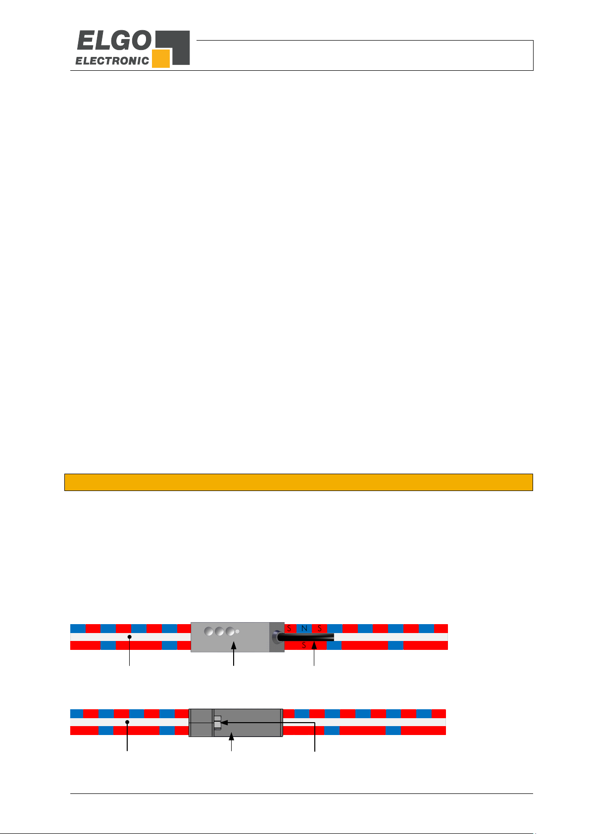
5.1 Functional principle
A Hall sensor and a magneto-resistive impedance measuring bridge are guided over a two-track magnetic tape
with a fine-interpolation trace and an absolute track. Together with the sensor line the absolute track provides
an absolute value and the fine-interpolation trace provides together with the interpolation electronic the measuring systems high resolution.
The fine interpolation track encloses alternately north- and south-pole tracks with a distance of 5 mm. These are
scanned with resistance bridges and provide a resolution of 0.01 mm. The absolute value provides the sensor
line with 16 single Hall sensors; these sensors are scanning the code sections of the north and south poles. The
absolute value on the magnetic tape recurs every 10 m with an EMAX resp. every 20 m with an EMAL system.
Figure 1: Coding of the magnetic tape
Technical Data
- 10 -
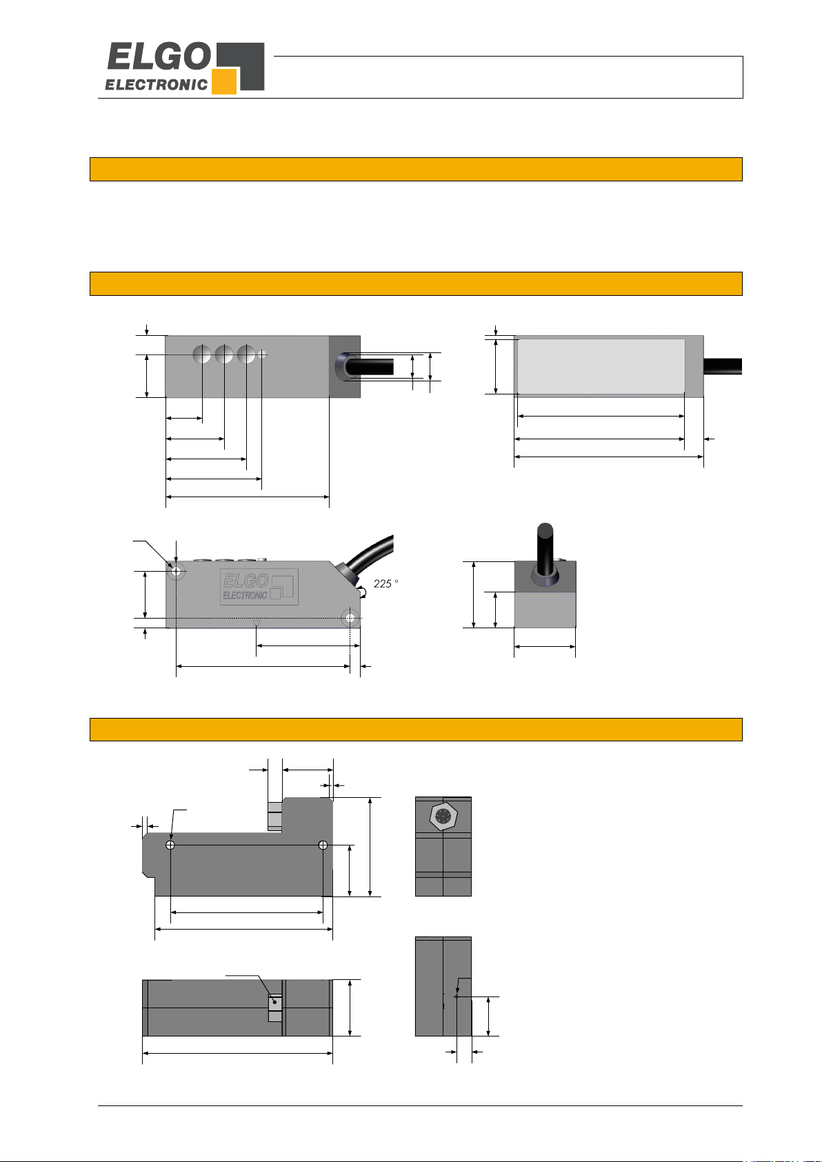
14.1
22.5
30.9
37.1
63.5
19.6 4.4
75
66
67.5
7.5
20.6
1.7
Ø 3.3 Ø 6.8
184
4
40
67
Ø approx. 9
Ø approx. 11
14.5
24
26
70
75
60
2x45°
20.25
Ø 3.3
1.5x45°
20
22
SW10
5.5
39
15.5
5.8
Ø 1.2
6 Technical Data
6.1 Identification
The type label serves for the identification of the unit. It is located on the housing of the sensor and gives the
exact type designation (=order reference, see type designation) with the corresponding part number.
Furthermore, the type label contains a unique, traceable device number.
When corresponding with ELGO always indicate this data.
6.2 Dimensions Sensor Housing with Cable Outlet
Figure 2: Dimensions of sensor with cable outlet
6.3 Dimensions Sensor Housing with M9 round connector
Figure 3: Dimensions of sensor with M9 round connector
Technical Data
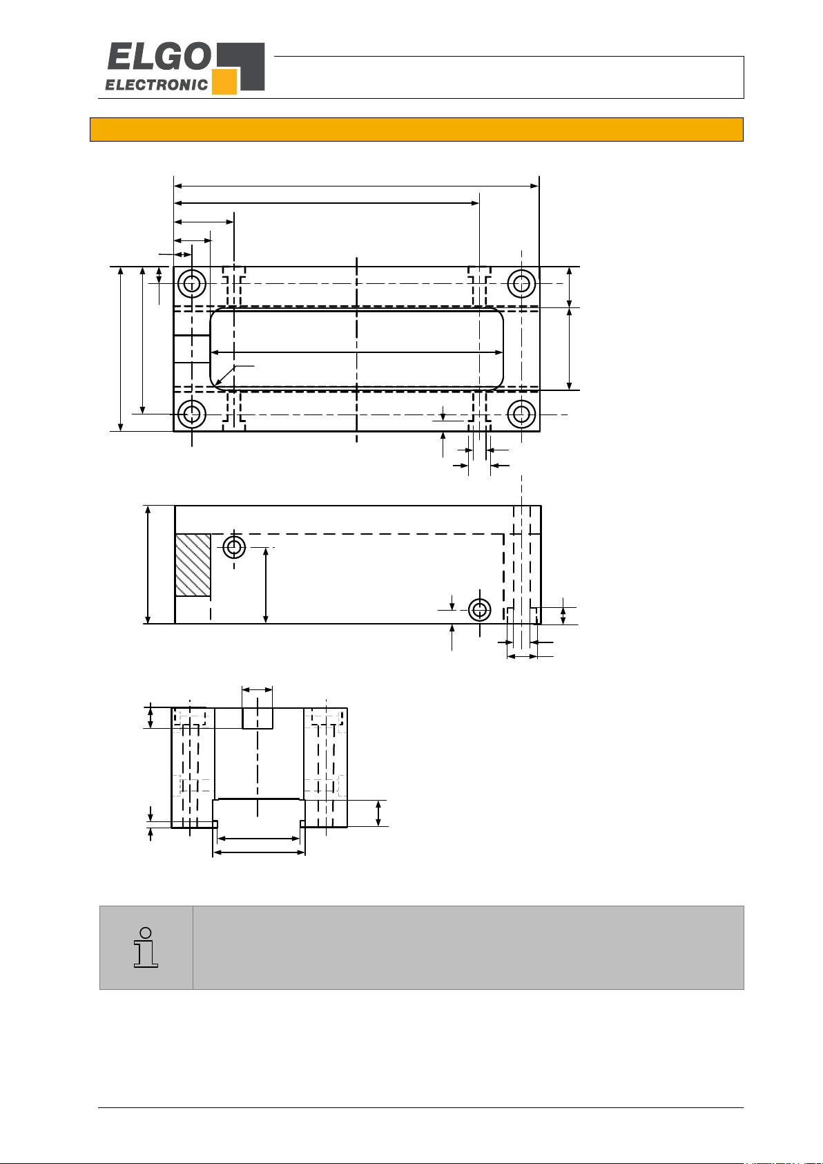
- 11 -
REMARK!
The accessorial guide carriage FW2080 ( 12.2) is only available for
the housing version with a fixed cable outlet ( 6.2).
83.5
16.5
10
5
5
48
43
12 24
3
R=4
80
Ø 4.5
Ø 8
4.5
20
4
34
1.5
6
8
8
22
25
Ø 3.5
Ø 6
100
Top view:
Side view:
Rear view:
6.4 Dimensions Guide Carriage FW2080
Figure 4: Dimensions of guide carriage FW2080

Technical Data
- 12 -
EMAX / EMAL (standard version)
Mechanical Data
Measuring principle
absolute
Measurement
linear
Repeat accuracy
±1 Increment
System accuracy in µm at 20°C
(L = measuring length in meters)
±(150 + 20 x L) (standard 010 12)
±(50 + 20 x L) (option F10 12)
Distance sensor / magnetic tape
max. 1.5 mm (2.0 mm with reduced measuring accuracy)
Basic pole pitch
5 mm
Sensor housing material
with cable outlet: zinc die cast
with M9 connector: aluminium
Sensor housing dimensions
a) Version with cable outlet: W x B x H = 75 x 24 x 26 mm,
resp. a) with FW2080 ( 12.2): W x B x H = 100 x 34 x 48 mm
b) Version with M9 connector: W x B x H = 75 x 22 x 39 mm
Required magnetic tape
EMAX: AB20-50-20-R-11
EMAL: AB20-50-10-R-12
Maximum measuring length
EMAX up to 10 m
EMAL up to 20 m
Connections
Version with cable outlet: open cable ends (more options 12)
Version with M9 connector: via DKA cable (accessories 12.2)
Sensor cable
Version with cable outlet: 1.5 m standard length (others upon request)
Version with M9 connector: no cable (accessorial part, see 12.2)
Weight
Sensor approx. 100 g without cable, (cable approx. 60 g/m)
Electrical Data
Supply voltage
+ 10 … 30 VDC
Residual ripple
10 … 30 V: <10%
Power input
max. 150 mA
Interfaces
SSI, CAN, RS422, RS232 oder IO-Link acc. to IEC 61131-9
Resolution
0.01 mm
Speed
max. 4 m/s
Conditions
Storage temperature
-20 °C … +85 °C
Operation temperature
-10 °C … +70 °C
(-25 °C … +85 °C upon request)
Humidity
max. 95 %, not condensing
Protection Class
IP40 (standard)
IP65 (option V)
6.5 Technical Data Sensor

Technical Data
- 13 -
Magnetic Tape AB20-50-20-2-R-11 and AB20-50-20-2-R-12
Coding
absolute, dual track system
Pole pitch
5 mm
Operation temperature installed
−20 °C … +65 °C
(−20°C … +80°C when using without adhesive tape, options „B“ or „D“)
Storage temperature uninstalled
Short-term: −10°C … +60°C
Medium-term: 0°…+40°C
Long-term: +18°C
(−20°C … +80°C when using without adhesive tape, options „B“ or „D“)
Gluing temperature:
+18°C … +30°C
Relative humidity
max. 95 %, non-condensing
System accuracy in µm at 20°C
(L = measuring length in meters)
±(150 + 20 x L) (standard 010 12)
±(50 + 20 x L) (option F10 12)
Material carrier tape
Precision Strip Steel 1.4310 / X10CrNi 18-8 (EN 10088-3)
Double-faced adhesive tape
3M-9088 (observe instructions), others on request
Dimensions
20 mm (±0.3 mm) x 1.8 mm (±0.1 mm)
Length expansion coefficient
16 x 10-6 1/K
Thermal length expansion
∆L[m] = L[m] x [1/K] x ∆[K]
(L = tape length in meters, ∆ = relative temperature change)
Available measuring lengths
EMAX: max. 10 m
EMAL: max. 20 m
min. 0.2 m
Weight magnetic tape
ca. 62 g/m (incl. magnetic tape and cover tape)
Tape imprint
ELGO standard, printing color black, digit height >= 5 mm
Influence of external magnets
External magnetic fields must not exceed 64 mT (640 Oe; 52 kA/m) on
the surface of the magnetic tape as this could damage or destroy the code
on the tape.
Protection class
IP65
6.6 Technical Data Magnetic Tape
The magnetic tape consists of two components:
The actual magnetic tape which carries the position information
A mechanical stainless steel back iron

Installation and First Start-Up
- 14 -
CAUTION
Please read the operating manual carefully before using the device! Strictly observe the Installation instructions! In case of damage caused by failure to observe this operating manual, the
warranty expires.
ELGO is not liable for any secondary damage and for damage to persons, property or assets.
The operator is obliged to take appropriate safety measures. The first start-up may only be
performed by staff that has been trained and authorized by the operator.
WARNING!
Do not use the device in explosive or corrosive environments!
The device must not be installed close to sources of strong inductive or capacitive interference
or strong electrostatic fields!
CAUTION!
The electrical connections must be made by suitably qualified personnel in accordance with
local regulations.
The device may be designed for switchboard mounting. During work on the switchboard, all
components must be de-energized if there is a danger of touching the energized parts!
(protection against contacts)
Wiring works may only be performed in the de-energized state!
Thin cable strands have to be equipped with end sleeves!
Before switching on the device, connections and plug connectors have to be checked!
The device must be mounted in a way that it is protected against harmful environmental influences such as splashing water, solvents, vibration, shock and severe pollution and the operating temperature must not be exceeded.
7 Installation and First Start-Up
7.1 Operating Area

Installation and First Start-Up
- 15 -
NOTE External Magnetic Fields
The magnetic tape must not be influenced by external magnetic fields!
The magnetic tape must not come into direct contact with other magnetic fields (e.g. permanent magnets, magnetic clamps, electromagnets, magnetic stands)! This may cause irreparable damage, which will compromise the measuring accuracy or even the functioning.
Pos. 1: Stainless steel cover tape
Pos. 2: Double-sided tape
Pos. 3: Magnetized plastic tape
Pos. 4: carrier tape stainless steel
Pos. 5: Double-sided tape
Pos. 6: Mounting surface, for example machine bed
7.2 Installation of the Magnetic Tape
7.2.1 Structure of magnetic tape
In the standard case, the magnetic tape is delivered as described
It is installed by gluing it to the respective mounting surface.
The magnetic tape consists of 2 pre-assembled components (Figure 5: Components of the magnetic tape):
A magnetized, flexible plastic tape (Pos. 3), which is connected with a magnetically conductive steel
tape as inference band (Pos. 4) and is supplied with an adhesive tape (Pos. 5).
A magnetized permeable cover tape (Pos. 1), which serves for the mechanical protection of the plastic
tape (not required for the measurement) and is supplied with an adhesive tape (Pos. 2).
Therefore a divergent tape structure and scope of delivery is also possible.
The cover tape is also available separately
Figure 5: Components of the magnetic tape

Installation and First Start-Up
- 16 -
Magnetized
Plastic tape
Steel tape
7.2.2 Handling
In order to avoid tension in the tape, it must not be stretched, compressed or twisted.
It should be stored with the magnetized plastic tape to the outside, the minimum bending radius must be noted
here
Figure 6: Handling
7.2.3 Processing hint for the gluing of magnetic tapes
Surface-Preparation: In order to guarantee optimal adhesion, all antiadhesive contamination (e.g. oil, grease,
dust, separating agents) has to be removed using solvents with residue-free evaporation.
Suitable agents are ketones or alcohols. Typical solvents for cleaning the surface are a 50/50 isopropyl alcohol/water mixture or heptane. Those agents are offered by Loctite and 3M among others as surface cleaners.
When using solvents, always observe the manufacturer instructions! If the surface is copper, brass etc., it should
be sealed to avoid oxidation.
Contact-Pressure: The strength of the adhesion is directly dependent on the contact the adhesive can form with
the surface. Therefore it is important to use as much pressure as possible when gluing the tape, possibly by using aids such as draw rolls. The optimum contact pressure is 4…5 kg/cm2).
Gluing temperature: The optimal gluing temperature is between + 21 ° C and 38 ° C. Avoid colder sticking
surfaces than + 10 °C, because in this case the adhesive becomes too hard and perhaps a sufficient immediate
adhesion is hardly to achieve. After proper sticking, the stability of the connection is ensured also when the temperature is below zero. The final tackiness of a sticking is from experience reached after approximately 72 hours
(at + 21 °C). For gluing use only the supplied adhesive tape.

Installation and First Start-Up
- 17 -
Length cover tape = measuring length + sensor length + 50mm (end caps)
NOTE!
When sticking the magnetic tape pay attention to the markings on the tape and the Sensor.
Improper installation does not provide the correct values. A already glued magnetic tape is
destroyed after the removal, and cannot be used again. Note also the direction of counting
of the measuring system
Preferably the magnetic tape should be glued close to an edge or into a groove, which
should be deep enough to embed the magnetic tape and the cover tape.
When unprotected, the cover tape may peel off!
Therefore:
Use tape end caps (see chapter 9.2) or let the cover tape overlap* the end of the magnetic
tape and fix it with a screw.
7.2.4 Cutting and Gluing
Before starting the gluing process, both the magnetic and the cover tape have to be cut to the required length
The tape must be glued smoothly on the surface. The measuring accuracy decreases if the tape is not even!
Before gluing the magnetic tape and the cover tape onto the surface, they should be left lying on the mounting
surface for ca. 30 minutes so that the temperature matches. This prevents strain in the tape due to thermal expansion.
Mounting steps:
1. Thoroughly clean surface (7.2.3)
2. Let magnetic tape and cover tape adjust their temperature (acclimatization)
3. Remove protection foil of adhesive tape on magnetic tape
4. Glue the magnetic tape by using great pressure
5. Thoroughly clean the surface of magnetic tape
6. Remove the protection foil of adhesive tape on cover tape
7. Glue the cover tape by using great pressure
8. Safeguard the ends of the cover tape against peeling off (e. g. by using end caps 12.2)

Installation and First Start-Up
- 18 -
NOTE!
The correct distance sensor / magnetic tape is monitored and displayed by the LED on the
top resp. on the front sensor (depends on design). Distance not correct LED glow red
The mounting tolerances given below are valid for both housing types
(standard version with fixed cable outlet or sensor housing with round connector).
Tolerances
Magnetic tape type
AB20-50-20-2-R-11 and AB20-50-20-2-R-12
Ride height (distance to the tape)
0.1 … 1.5 mm
Pitch
The max. Distance 1.5 mm must not be exceeded at any position
Yaw angle
0 ° ±0.5 °
Roll
The max. Distance 1.5 mm must not be exceeded at any position
Lateral offset
±0.5 mm
0.1 – 1.5 mm
Ride height
Pitch
Yaw angle
Roll
Lateral offset
±0.5 mm
<±0.5 °
Max. 1.5 mm
Max. 1.5 mm
7.3 Installation of the Sensor
In order to fasten the sensor head, two M3 must be used.
7.3.1 Mounting Tolerances
Further, the following tolerances must be observed:
Table 1: Mounting tolerances
Figure 7: Tolerances

Installation and First Start-Up
- 19 -
NOTE!
An offset is necessary in each case of a replacement of the EMAX / EMAL or magnetic tape.
fine interpolation track
non-magnetized area
absolute track
N
S N S N S
N N N NS S S S N N N NS S S S N NS S
S N S N S
Magnetic tape EMAX / EMAL Cable outlet
fine interpolation track
non-magnetized area
absolute track
N
S N S N S
N N N NS S S S N N N NS S S S N NS S
S N S N S
Magnetic tape EMAX / EMAL Round connector
Sensor with cable outlet:
Sensor with M9 round connector:
7.3.2 Mounting Direction of EMAX / EMAL Sensor to Magnetic Tape
Since the magnetic tape has two magnetized tracks, the sensor and magnetic tape must always be mounted in
the correct direction in order to obtain correct measurement results.
Marking arrows on the tape and sensor clearly indicate the correct mounting direction.
The pole finder foil, which is available as an accessory ( 12.2) and is placed on the magnetic tape, can also
be used to determine the respective pole pitches. The pole pitches result in the following mounting direction:
Figure 8: Mounting direction on magnetic tape
The sensor center must be aligned to the magnetic tape center (±0.5 mm)
Markers on tape and sensor are additionally indicators for the mounting direction
When using the accessorial option FS-1000 ( 12.2), the mounting direction is marked on the guide rail
7.4 Offset Calibration
After the installation of magnetic tape and measuring system (sensor head), a value is transmit via interface.
Since this value does not correspond to the machine zero point, it should be possible to store an offset on the
control side.

Interfaces
- 20 -
Position
Code
1
Binary
0
Gray
REMARK!
No coding switches are accessible on the sensor housing with M9 round
connector. Therefore, please specify the desired configuration when ordering!
T
Tm-T/2
1 1 G23 G22 G21 G20 G19 G18 G17 G16 G15 G14 G13 G12 G11 G10 G9 G8 G7 G6 G5 G4 G3 G2 G1 G0 PFB 0 1
1 2 3 4 5 6 7 8 9 10 11 12 13 14 15 16 17 18 19 20 21 22 23 24 25
Non-inverted SSI-Clock
+ 1 Power Failure Bit
24 Bit
PFB = Power failure bit
T = Cycle duration of the clock signal
TM = Monoflop time >15 µs
Gray/binary switchover
0
4
8
C
Not inverted SSI Clock
8 Interfaces
The following chapters give detailed information about the available interfaces.
8.1 Interface SSI (option SB0 and SG0)
Principle of the function: If the clock is not interrupted for the time Tm-T/2 (output of further 25 periods), the shift
register clocks once again the same data value (error recognition in evaluation). With the SSI interface, transmission frequencies up to max. 250 KHz can be ensured. The SSI interface is generally terminated with an internal terminating resistor.
Some encoders contain a Power Failure Bit (PFB):
With EMAX the PFB is always „low“, unless the maximum allowed distance from sensor to tape is exceeded.
Figure 9: SSI - reading the data
By using the rotary code switch, which is located behind a protection cap (see figure below), the data format of
the SSI interface can be set to Gray or binary code.
Figure 10: SSI - Gray / binary switchover

Interfaces
- 21 -
Position
Bit rate (left)
Position
CAN identifier (right)
0
- 0
Identifier from memory
1
- 1
181
2
- 2
182
3
- 3
183
4
- 4
184
5
- 5
185
6
- 6
186
7
- 7
187
8
bit rate from memory
8 188
9
1 MBit/s 9
189
A
800 kBit/s
A 18A
B
500 kBit/s
B 18B
C
250 kBit/s
C 18C
D
125 kBit/s
D 18D
E
100 kBit/s
E 18E F 50 kBit/s F
18F
REMARK!
No coding switches are accessible on the sensor housing with M9 round
connector. Therefore, please specify the desired configuration when ordering!
LSB MSB LSB MSB
Position Velocity
Bit rate CAN identifier
0
4
8
C
0
4
8
C
All available CAN options
and information about the
DS406 device profile can
be found in the corresponding EDS or XDD file.
Download:
https://www.elgo.de/filead
min/user_upload/software/
EMAX_DS406.zip
8.2 Interface CANopen (option CA0)
When ordering option “CA0”, the encoder is equipped with a CAN interface according to the CANopen standard DS406. To start the communication (start sending) an NMT command must be given first. If the position
value is needed to be sent automatically after power on, the special version 11 can be ordered ( 12).
The following identifiers are given:
CAN - Identifier
(6 byte telegram)
181 h (16) = Identifier
First 4 bytes = Position (resolution 0.01 mm), bit rate 250 KB/s
Following 2 bytes = velocity in mm/s
The CAN-Identifier can be adjusted in the range of 181(16) to 18F(16) by rotary code switches, which are located
behind a protection cap on the top of the sensor housing:
Figure 11: Bit rate and CAN identifier settings
Table 2: Bit rate and CAN-Identifier with option CA0

Interfaces
- 22 -
80 (16) + EMAX address
Identifier to request the absolute position
10 (16) + position of rotary code switch
Identifier contains absolute position of the device
(4 byte telegram)
EMAX / EMAL (resolution 0.01 mm)
Status
X = 0 → no errors
X = 1 → magnetic tape error
Position
Bit rate (left)
Position
Address (right)
0
1 MBit/s 0 0 1
500 kBit/s
1 1 2 250 kBit/s
2 2 3 125 kBit/s
3 3 4 100 kBit/s
4 4 5 - 5 5 6
- 6 6 7
- 7 7 8
- 8 8 9
- 9 9 A
- A
A
B
- B B C
- C C D
- D D E
- E E F
- F
F
REMARK!
No coding switches are accessible on the sensor housing with M9 round
connector. Therefore, please specify the desired configuration when ordering!
Bit rate Address
0
4
8
C
0
4
8
C
MSB LSB X
Position Status
PC/SPS/PLC EMAX/EMAL
8.3 CAN BASIC ELGO (Option CN0)
Interface / Protocol: When ordering option “CN0”, the EMAX / EMAL encoder is equipped with a CAN interface
according to the ELGO CAN standard protocol. The following identifiers are given:
Table 3: Identifier Option CN0
4 byte acknowledgement telegram:
Figure 12: Bit rate / address (option CN0)
The settings of bit rate and address (range from 0 (16) to F (16)) be done by using the rotary coding switches, which
are located behind a protection cap on the top of the sensor housing.
Table 4: Bit rate and address settings (option CN0)

Interfaces
- 23 -
PLEASE NOTE:
With the sealed option V or sensor housings with round connector, the above-mentioned
terminating resistor is not accessible! If no terminating resistor is required for these variants,
this can be specified by ordering option A (see 12 Type Designation).
TERM
LED
TERM
LED
0
4
8
C
0
4
8
C
0
4
8
C
0
4
8
C
+
(A - A)
A
A
120 Ω
R1
R1
R1
R1
By default, the 120 Ω termination impedance
is enabled (see "ON" setting in the figure).
In order to deactivate the termination impedance, use a micro screwdriver and turn counter-clockwise up to the stop.
Termination resistor: ON
Termination resistor: OFF
8.4 Termination Resistor
As standard the interfaces CANopen and addressable RS422, is supplied with an internal 120 Ω termination
resistor. For sensors with a fixed cable outlet, this can be deactivated via a trimmer located under a protective
cap right next to the LED.
Figure 13: Termination resistor ON / OFF
Example of a follow-up circuit:

Interfaces
- 24 -
Position
Baud rate
8
9600 bit/s
9
600 bit/s
A
1200 bit/s
B
2400 bit/s
C
4800 bit/s
D
19200 bit/s
E
38400 bit/s
F
115200 bit/s
REMARK!
No coding switches are accessible on the sensor housing with M9 round
connector. Therefore, please specify the desired configuration when ordering!
Standard
9600 bit/s, 8 data bits, 1 stop bit, no parity
7 Bytes, 02 MSB MSB-1 LSB 03 00 0D
binary position value
STX ETX
Bit rate
0
4
8
C
8.5 Interface RS422 (Option 420) & RS232 (Option 230)
Depending on the order specification the encoder can be equipped with a RS422 (option “420”) or RS232
interface (option “230”). Both versions use the same protocol and differ only in their level height.
The data transmission has the following format:
1 Start Bit / 8 Data Bits / 1 Stop Bit / No Parity
Data protocol:
The actual value is transmitted with 9600 bit/s, 8 data bits, 1 stop bit, without parity bit in the following format:
02h STX
xxh ABS data MSB
xxh ABS data
xxh ABS data LSB
03h ETX
00h
0Dh
The scanned absolute position is shown binary with 0.01 mm resolution in the 3 ABS data bytes.
Other protocols are available on request.
Table 5: Bit rate RS422 (option420) and RS232 (option 230)
RS422: Further an addressable version is available as option “A20” ( 8.6).

Interfaces
- 25 -
Table 6: Addressable RS422 Option A20
Position
Bit rate (left)
Position
Address (right)
0
9600 bit/s addressable [adrb]
0 0B 1 600 bit/s [adrb]
1 0C 2 1200 bit/s [adrb]
2 0D 3 2400 bit/s [adrb]
3 0E 4 4800 bit/s [adrb]
4 0F 5 19200 bit/s [adrb]
5 10 6 38400 bit/s [adrb]
6 11 7 115200 bit/s [adrb]
7 12 8 9600 bit/s auto send [asnd]
8 13 9 600 bit/s [asnd]
9 14
A
1200 bit/s [asnd]
A 15
B
2400 bit/s [asnd]
B 16 C 4800 bit/s [asnd]
C 17
D
19200 bit/s [asnd]
D 18
E
38400 bit/s [asnd]
E 19 F 115200 bit/s [asnd]
F 1A
REMARK!
No coding switches are accessible on the sensor housing with M9 round
connector. Therefore, please specify the desired configuration when ordering!
Bit rate Address
0
4
8
C
0
4
8
C
8.6 RS422 Addressable Version (Option A20)
The device address can be defined by using a rotary code switch that is located behind a protective cap on the
top of the sensor housing:
Figure 14: Set options on top of the housing

Interfaces
- 26 -
General format of a message to the EMAX or EMAL:
0x02 Byte1 Byte2 Byte3 0x03
STX check ETX
General format of a message from the EMAX or EMAL:
0x02 Byte1 Byte2 Byte3 Byte4
STX
Position-request from the EMAX or EMAL with address i:
Message to the EMAX or EMAL
0x02 0x04 i check 0x03
STX check ETX
Answer of the requested EMAX or EMAL:
0x02 PosHigh PosMid PosLow EMAX address
Message to the EMAX or EMAL:
0x02 0x05 0x05 0x0c 0x03
STX address request check ETX
Answer of the EMAX or EMAL:
0x02 0xff 0xff i 0x03
STX EMAX address ETX
EMAX or EMAL answers:
0x02 0xff 0xff Err 0x03
STX 0xff 0xff Error Code ETX
With Err = 0x04... 0x0a
Protocol of an addressable EMAX / EMAL:
0x02 (STX) starts a message
0x03 (ETX) close the message
Byte3 (check) is the arithmetic sum of 0x02(STX), Byte1 and Byte2.
ETX is not included in the checksum
0x04 characterizes the message as position-request
i is the address of the requested EMAX / EMAL (i = 0x0b... 0x7f).
The position value consists of 3 byte:
PosLow (bit 0… bit 7), PosMid (bit 8… bit15), PosHigh (bit16...bit23).
Bit 0 has the value10 µm. Position-values are always smaller than 0xffff00.
Please note: The last byte is no ETX, like in all the other messages, but the EMAX / EMAL address.
Interrogation of the address of an EMAX / EMAL:
Connect always only a single EMAX / EMAL to be interrogated via RS422/RS232 converter to COM port of a
PC.
Note: The combination 0xff 0xff does not appear in normal mode for position answers of EMAX / EMAL (directly
after STX) It is a sign for a special message not a position (in this case with 0x0b <= i <=0x7f it is the answer
to the interrogation of the address).
Negative answer: If one of the described operations failed for some reasons, the EMAX / EMAL encoder will give
a negative answer with a concerning error code.

Interfaces
- 27 -
Code
Description
0x04
Wrong succession of bytes sent to EMAX / EMAL for example if the 4. byte after the STX is no ETX or
the byte after STX is not 0x04, 0x05 or 0x06.
0x05
Receive Error: Error concerning the interface
(for example if there has been sent a message with a wrong baud rate etc.)
0x06
Invalid EMAX / EMAL address: appears while trying to assign an address less than 0x0b or greater than
0x7f.
0x07
Lost EMAX / EMAL Address: The check of the internal, redundant stored address is failed. This message
is issued immediately after the reconnecting the power supply, if an error was found during reading out
the EEPROM's or the problem cannot be resolved by an redundant stored address.
0x08
Internal EEPROM- storage error.
0x09
Error in calculation of position (No tape, tape damaged or to big distance)
0x0a
Check-Sum-Error - Check-Sum of a message sent to EMAX / EMAL is wrong
Data out
Enable
Data in
TX-
TX+
RX-
RX+
120R
120R
RS422 MASTER
EMAX-422 #1
EMAX-422 #n
Data in
TX Enable
Data out
Data in
TX Enable
Data out
Color
Function
Green
RX+
Violet
RX−
Yellow
TX+
Orange
TX−
Brown
+ 24 VDC
White
0 V / GND
Table 7: Error messages of an addressable EMAX / EMAL
8.7 Connection to a RS422 Master
Figure 15: Connection to a RS422 Master

Interfaces
- 28 -
Byte
3 2 1
0
Measurement value
8.8 IO-Link Interface
The IO-Link interface is available in both designs (housing with fixed cable outlet or with round connector).
8.8.1 Connections
In order to comply with the IO-Link standard, the housing variant with fixed cable outlet is supplied with
a 4-pin M12 (male) round connector with the IO-Link standard pin assignment.
Pin assignment see 10.1.5
For versions with IO-Link and additional incremental output (see 9) the 4-pin IO-Link standard round
connector is no longer sufficient. Here, the sensor cable is supplied with open cable ends as standard.
Optionally, the cable can be supplied with a 12-pin M12 (male) round connector
(see 12 Type Designation Connection options "RCM0").
Pin assignment see 10.1.6
For the housing version with round connector, an additional DKA cable with the M12 round connector
mentioned above and identical pin assignment is available as an accessory (see 12.2 Accessories).
For this version no incremental outputs (see option 9) are available.
Pin assignment see 10.2.2
8.8.2 Functional Description
The IO-Link interface integrated in the sensor enables continuous communication between the system controller
and the field level.
Position information and errors are independently reported to the controller and can be easily viewed.
Conversely, format adjustments, for example, can be set up more easily.
8.8.3 Process Data
EMAX-IO cyclically transmits a measurement value via the IO-Link interface.
Properties of the measurement value:
signed
is output in µm
32 bit format
index 28 (16)
8.8.4 Set Zero
1. Move the EMAX-IO sensor to the desired position.
2. Write E0 (16) on Index 2 / Subindex 0 via system command “Set Zero”.
3. EMAX-IO calculates the offset so that zero is output at the approached position.
8.8.5 Download Data Sheet
The download of the complete data sheet with all relevant data, commands and parameters can be found on:
https://www.elgo.de/fileadmin/user_upload/pdf/flyer/sensors/EMAX-IO-000-TD-E.pdf

Optional Incremental Output
- 29 -
Parameter
Description
min.
typ.
max.
Einheit
Medium voltage
Um (sin) / Um (cos)
2.4
2.5
2.6
V
Amplitude
sin – sin‘ / cos – cos‘
400
500
600
mV
Ratio
(sin – sin‘) / (cos – cos‘)
0.9
1.0
1.1
-
Difference of Phase
85
90 ±10 %
95
° Grad
Distortion factor
K
- - 3
%
B
A
90°
HTL: 10 … 30 V
TTL : 5 V
0 V
cos
cos
Um (cos)
Signal voltages
Distance S
sin
sin
Um (sin)
Differential signal (cos - cos)
Differential signal (sin - sin)
0
Signal voltages
Distance S
0
5 mm
5 mm
9 Optional Incremental Output
Note: This option is only available for EMAX/EMAL sensor designs with fixed cable outlet.
9.1 Incremental A/B Signals (TTL / HTL)
Optionally two 90° phase shifted, rotary pulse encoder compatible square-wave signal outputs with HTL or TTL
level (push/pull) are available. Order specifications see 12 „Type Designation“.
Figure 16: A/B - Inkrementalsignale (TTL / HTL)
9.2 Sine/Cosine Incremental Signals (Option SC50)
Optionally an incremental sine/cosine output with 1 Vpp levels is available (push/pull, short-circuit proof).
Figure 17: Sine – Cosine Incremental Signals
Table 8: Characteristics values for option SC50

Pin Assignment
- 30 -
Color
SSI (SG0, SB0)
SSI (SG0, SB0) + Incremental HTL
White
0 V / GND
0 V / GND
Brown
+ 10 … 30 VDC
+ 10 … 30 VDC
Yellow
TX DATA +
TX DATA +
Orange
TX DATA −
TX DATA −
Green
CLK CLOCK +
CLK CLOCK +
Violet
CLK CLOCK −
CLK CLOCK −
Grey
-
HTL A (option)
Black
-
HTL B (option)
Shield
PE*
PE*
Color
SSI (SG0, SB0) + Sine/Cosine SC50
SSI (SG0, SB0) + Incremental TTL
White
0 V / GND
0 V / GND
Brown
+ 10 … 30 VDC
+ 10 … 30 VDC
Grey
TX DATA +
TX DATA +
Pink
TX DATA −
TX DATA −
Yellow
CLK CLOCK +
CLK CLOCK +
Green
CLK CLOCK −
CLK CLOCK −
Blue
1 Vpp SIN + (option)
TTL A (option)
Red
1 Vpp SIN − (option)
TTL A‘ (option)
Black
1 Vpp COS + (option)
TTL B (option)
Violet
1 Vpp COS − (option)
TTL B‘ (option)
Shield
PE*
PE*
Pin
Color
Function
1
White
0 V / GND
2
Brown
+ 10 … 30 VDC
3
Orange
DATA −
4
Yellow
DATA +
5
Violet
CLOCK −
6
Green
CLOCK +
7
-
-
8
-
-
10 Pin Assignment
10.1 Connections of Housing with fixed Cable Outlet
10.1.1 SSI-Interface
Table 9: Connections of SSI interface cable 1
Table 10: Connections of SSI interface cable 2
*) Connect shield only at the device!
Table 11: Connections of SSI interface with option M8F0, 8-pin M16 round connector

Pin Assignment
- 31 -
Pin
Color
Function
A
White
0 V / GND
B
Brown
+ 10 … 30 VDC
C
Green
CLOCK −
D
Yellow
CLOCK +
E
Grey
DATA +
F
Pink
DATA −
G
Blue
1 Vpp SIN + (option)
H
Red
1 Vpp SIN − (option)
J
Black
1 Vpp COS + (option)
K
Violet
1 Vpp COS − (option)
L
-
- M -
-
Pin
Color
Function
1
White
0 V / GND
2
Brown
+ 10 … 30 VDC
3
-
- 4 -
- 5 Blank
Shield
6
Green
CLOCK +
7
Violet
CLOCK −
8
Yellow
DATA +
9
Orange
DATA −
Pin
Color
Function
1
White
0 V / GND
2
Brown
+ 10 … 30 VDC
3
Orange
DATA −
4
Yellow
DATA +
5
Violet
CLOCK −
6
Green
CLOCK +
7
Grey
HTL A (option)
8
Black
HTL B (option)
Table 12: Connections of SSI interface with option MCM0, 12-pin M16 round connector
Table 13: Connections of SSI interface with option D9M0, 9-pin D-SUB connector
Table 14: Connections of SSI interface Option M8M0, 8-pin M16 round connector

Pin Assignment
- 32 -
Color
CAN (CA0)
CAN (CA0) + Incremental HTL
CAN (CA0) + Incremental TTL
White
0 V / GND
0 V / GND
0 V / GND
Brown
+ 10…30 VDC
+ 10 … 30 VDC
+ 10 … 30 VDC
Yellow
CAN HIGH
CAN HIGH
CAN HIGH
Orange
CAN LOW
CAN LOW
CAN LOW
Green
- - TTL A‘ (option)
Violet
- - TTL B‘ (option)
Grey
-
HTL A (option)
TTL A (option)
Black
-
HTL B (option)
TTL B (option)
Shield
PE*
PE*
PE*
Pin
Color
Function
1
-
- 2 Orange
CAN LOW
3
-
- 4 -
-
5
-
- 6 White
0 V / GND
7
Violet
CAN HIGH
8
-
- 9 - - Housing
Blank
Screen
10.1.2 CANopen Interface
Table 15: Connections of CANopen interface (open cable ends)
*) Connect shield only at the device!
Table 16: Connections of CANopen interface with option D9M, 9-pin D-SUB connector

Pin Assignment
- 33 -
Color
Function
White
0 V
Brown
+ 10 … 30 VDC
Yellow
TX (+)
Orange
TX (−)
Violet
RX (−) (only with A20 available)
Green
RX (+) (only with A20 available)
Grey
HTL A (option)
Black
HTL B (option)
Shield
PE*
Pin
Color
Function
1
White
0 V / GND
2
Brown
+ 10 … 30 VDC
3
-
- 4 -
- 5 Blank
Shield
6
Green
RX (+)
7
Violet
RX (−)
8
Yellow
TX (+)
9
Orange
TX (−)
Pin
Color
Function
1
White
0 V / GND
2
Brown
+ 10 … 30 VDC
3
Yellow
TX (+)
4
-
-
5
-
- 6 Orange
TX (−)
7
-
-
8
-
- 9 - - Housing
Blank
Shield
10.1.3 RS422 Interface
Table 17: Connections of RS422 interface (open cable ends)
*) Connect shield only at the device!
Table 18: Connections of RS422 interface with option D9M0, 9-pin D-SUB connector
Table 19: Connection of RS422 interface option D9M5, 9-pin D-SUB connector

Pin Assignment
- 34 -
Pin
Color
Function
1
White
0 V / GND
2
Brown
+ 10 … 30 VDC
3
Orange
TX (−)
4
Yellow
TX (+)
5
Violet
RX (+)
6
Green
RX (−)
7
Grey
HTL A (option)
8
Black
HTL B (option)
Color
Function
White
0 V / GND
Brown
+ 10 … 30 VDC
Yellow
RX
Orange
TX
Violet
-
Green
-
Grey
HTL A (option)
Black
HTL B (option)
Shield
PE*
Pin
Color
Function
1
White
0 V / GND
2
Brown
+ 10 … 30 VDC
3
Grey
HTL A (option)
4
Black
HTL B (option)
5
Blank
Shield
6
Yellow
RX 7 -
-
8
Orange
TX
9
-
-
Table 20: Connections of RS422 interface option M8M0, 8 pin M16 round connector
10.1.4 RS232 Interface
Table 21: Connections of RS232 interface (open cable ends)
*) Connect shield only at the device!
Table 22: Connections of RS232 interface with option D9M0, 9-pin D-SUB connector

Pin Assignment
- 35 -
4-pin M12
IO-Link interface (IOL)
1
+10 … 30 VDC
2 - 3
0 V / GND
4
C / Q
Color
IO-Link interface (IOL)
+ Incremental HTL
IO-Link interface (IOL)
+ Incremental TTL
IO-Link interface (IOL)
+ Sine/Cosine (SC50)
White
0 V / GND
0 V / GND
0 V / GND
Brown
+ 10 … 30 VDC
+ 10 … 30 VDC
+ 10 … 30 VDC
Yellow
- - -
Orange
C / Q
C / Q
C / Q
Green
HTL B (option)
TTL B (option)
1 Vpp COS + (option)
Violet
-
TTL B‘ (option)
1 Vpp COS − (option)
Grey
HTL A (option)
TTL A (option)
1 Vpp SIN + (option)
Black
-
TTL A‘ (option)
1 Vpp SIN − (option)
Shield
PE*
PE*
PE*
12-pin M12
IO-Link interface (IOL)
+ Incremental HTL
IO-Link interface (IOL)
+ Incremental TTL
IO-Link interface (IOL)
+ Sine/Cosine (SC50)
1
0 V / GND
0 V / GND
0 V / GND
2
+ 10 … 30 VDC
+ 10 … 30 VDC
+ 10 … 30 VDC
3
- - -
4
C / Q
C / Q
C / Q
5
- - - 6 - - - 7 HTL B (option)
TTL B (option)
1 Vpp COS + (option)
8
-
TTL B‘ (option)
1 Vpp COS − (option)
9
HTL A (option)
TTL A (option)
1 Vpp SIN + (option)
10
TTL A‘ (option)
1 Vpp SIN − (option)
11
- - -
12
- - -
10.1.5 IO-Link Interface
Table 23: Connections - cable outlet with 4-pin. M12 round connector
Note: The 4-pin M12 round connector and its assignment comply with the IO-Link standard.
10.1.6 IO-Link Interface with optional Incremental Output
Table 24: Connections - open cable ends (standard)
*) Connect shield only at the device!
Table 25: Connections - 12-pin M12 round connector (RCM0)

Pin Assignment
- 36 -
REMARK: Additional incremental outputs as well as sine/cosine
outputs are not available with the connector housing design ( 12).
Pin
SSI
CANopen
RS422
RS232
1
0 V / GND
0 V / GND
0 V / GND
0 V / GND
2
+10 … 30 VDC
+10 … 30 VDC
+10 … 30 VDC
+10 … 30 VDC
3
DATA (−)
CAN HIGH
TX (−)
RX
4
DATA (+)
CAN LOW
TX (+)
TX
5
CLOCK (−)
-
RX (−) - 6
CLOCK (+)
-
RX (+) - 7 - - - -
Color
SSI
CANopen
RS422
RS232
White
0 V / GND
0 V / GND
0 V / GND
0 V / GND
Brown
+10 … 30 VDC
+10 … 30 VDC
+10 … 30 VDC
+10 … 30 VDC
Orange
DATA (−)
CAN HIGH
TX (−)
RX
Yellow
DATA (+)
CAN LOW
TX (+)
TX
Violet
CLOCK (−)
-
RX (−)
-
Green
CLOCK (+)
-
RX (+)
-
7-pin M9 Pin
IO-Link
4-pin M12 Pin
IO-Link
1
0 V / GND
1 +10 … 30 VDC
2
+10 … 30 VDC
2 - 3
-
3
0 V / GND
4
-
4
C / Q
5
C / Q
6
-
7
-
10.2 Connections of Housing with M9 Round Connector
10.2.1 SSI / CANopen / RS422 / RS232
Table 26: Connections of the 7-pin M9 round connector (male)
Table 27: Connections when using the DKA cable with open cable ends
Order designation of the standard DKA cable: DKA-00-Q7F0-050-XXXX-06-N-N-N (see accessories 12.2)
10.2.2 IO-Link
Table 28: Connections IO-Link without cable Table 29: Connections IO-Link with DKA cable
Order designation of the IO-Link DKA cable: DKA-00-Q7F0-050-R4MA-04-N-N-N (see accessories 12.2)

Disturbances, Maintenance, Cleaning
- 37 -
CAUTION!
The device, the connection line and the signal cable must not be installed next to sources of interference that emit
strong inductive or capacitive interference or strong electrostatic fields.
External perturbations can be avoided thorough suitable cable routing.
The screen of the signal output cable should only be connected to the following circuit on one side. The screens
should not be grounded on both sides. Signal cables always have to be routed separately from the load power line.
A safety distance of at least 0,5 m has to be kept from inductive and capacitive sources of interference such as contactors, relays, motors, switching power supplies, clocked controllers etc!
If interferences occur in spite of all the items stated above being observed, please proceed as follows:
1. Installation of RC-circuits via contactor coils of AC-contactors (e.g. 0,1 µF / 100 )
2. Installation of recovery diodes via DC-inductors
3. Installation of RC-circuits via the different motor phases (in the terminal box of the motor)
4. Do not connect protective earth and ground
5. Connect a mains filter ahead of the external power pack
WARNING!
Danger of injury through non-conventional fault clearance!
Non-conventional fault clearance can lead to severe injuries and damage of property.
Therefore:
Any work to clear the faults may only be performed by sufficiently qualified staff
Arrange enough space before starting the works
Make sure that the mounting area is clean and tidy. Loose components and tools are sources of accidents.
If components need to be replaced:
Pay attention to a correct installation of the spare parts.
Reinstall all the fixing elements properly
Before turning on the device, ensure that all covers and safety equipment is installed correctly and functions
properly
WARNING!
The device can only be cleaned with a damp cloth, do not use aggressive cleanser!
11 Disturbances, Maintenance, Cleaning
This chapter describes possible causes for disturbances and measures for their removal. In case of increased disturbances, please follow the
measures for fault clearance in chapter 11.1. In case of disturbances that cannot be eliminated by following the advice and the fault clearance measures given here, please contact the manufacturer (see second page).
11.1 Fault Clearance
11.2 Re-start after Fault Clearance
After the fault clearance:
1. Reset the emergency stop mechanism if necessary
2. Reset the error report at the super-ordinate system if necessary.
3. Ensure that there are no persons in the danger area.
4. Follow the instructions from chapter 7.
11.3 Maintenance
The device is maintenance-free.
11.4 Cleaning

Type Designation
- 38 -
Serie/Typ:
Version:
Sensor housing / Connections:
000 = no cable, sensor housing with M9 round connector
(Important: different housing design - see dimensions)
015 = sensor housing with fixed cable outlet (1.5 m standard
cable length, other lengths on request available)
00 = 00 (standard) 01… 99 (special versions)
11 = EMAX sends automatically without NMT
command and has 4 bytes position output
without velocity output
Resolution in µm:
010 = 10 µm - at system accuracy in µm ±(150 + 20 x L)
F10* = 10 µm - at system accuracy in µm ±(50 + 20 x L)
* variant F10 at extra charge
Interface:
SB0 = SSI interface (25 Bit binary code)
SG0 = SSI interface (25 Bit Gray code)
CA0 = CANopen (DS406)
CN0 = CAN BASIC ELGO
420 = RS422
A20 = addressable RS422
230 = RS232
IOL* = IO-Link acc. to IEC 61131-9
Bit Rate:
09k6 = 9600 bit/s - standard with RS232 (230) and 422 (420/A20)
19k2 = 19200 bit/s with RS232 or RS422
38k4 = 38400 bit/s with RS232 or RS422
125k = 125000 bit/s with CAN
250k = 250000 bit/s with CAN
500k = 500000 bit/s with CAN
1MHz = 1000000 bit/s with CAN
230k = 230400 bit/s with IO-Link
B
C
D
E
F
G
Additional Options
0 = device address 0… F (standard setting = 0)
H
- - - - = without connector (open cable ends)
D9M = 9-pin (male) D-SUB (only for CAN interfaces available)
D9M0 = 9-pin (male) D-SUB (available for RS232, RS422 and SSI) with ELGO standard pin assignment
D9M5 = 9-pin (male) D-SUB (only for RS422 with Bit rate 09k6) with Option 5 (pin assignment suitable for Z25 indicators)
M8F0 = 8-pin (female) M16 connector with ELGO standard SSI assignment, suitable for ELGO PNO1 (only for SSI)
M8M0 = 8-pin (male) M16 connector (only for RS422 and SSI available)
R5M0 = 5-pin (male) M12 connector with ELGO standard assignment (only for CAN interfaces available)
RCM0 = 12 -pin (male) M12 connector (intended for IO-Link interfaces with additional Sin/Cos or A/B signals)
MCM0 = 12-pin (male) M16 connector (intendedfor SSI interfaces with additional Sin/Cos or A/B signals)
MCF0 = 12-pin (female) M16 connector (intended for SSI interfaces with additional Sin/Cos or A/B signals)
Address
Connection options*
I
J
K Incremental output*
H2N5 = Incremental square wave signals HTL with 2.5 µm resolution
H005 = Incremental square wave signals HTL with 5 µm resolution
H010 = Incremental square wave signals HTL with10 µm resolution
H025 = Incremental square wave signals HTL with 25 µm resolution
T2N5 = Incremental square wave signals TTL with 2.5 µm resolution
T005 = Incremental square wave signals TTL with 5 µm resolution
T010 = Incremental square wave signals TTL with10 µm resolution
SC50 = Sine/Cosine signal output 1 Vpp, pole pitch = 5 mm
Presetting of the rotary code switch by ELGO is
possible on request! Please note: For versions
with M9 round connector on housing or with
sealed option V, the configuration must
generally be specified when ordering.
V = Sealed IP65 construction (Important note: This variant is delivered without rotary code switches.
Please specify your configuration when order, since no more settings can be made after sealing.)
A = CAN interface resp. addressable RS422 without internal termination resistor
A
AAAA BB CCC DDD EEE FFFF G HHHH I J KKKK
EMAX = Measuring length up to 10 m
EMAL = Measuring length up to 20 m
(available at extra charge)
*) Connection options apply only to versions with fixed cable outlet
*) For technical reasons, this option is not available for versions
with connectors on the housing. The incremental outputs are
only available for versions with fixed cable outlet.
IO-Link versions with optional incremental output are supplied
with open cable ends or optionally with a 12-pin M12 round
connector; see connection options "RCM0" (others on request).
*) The standard IO-Link version generally has
a (male) 4-pin M12 round connector with
standard IO-Link assignment.
12 Type Designation

Type Designation
- 39 -
NOTE
When ordering, please use the ordering code (Type Designation) described on the previous
page. Options that are not required are filled in with „-„.
Order description
Description
EMAX00015010SB0---------------
EMAX with binary SSI interface, 25 bit and 1.5 m cable
EMAX0001510SB0-----M8F0------
EMAX with binary SSI interface, 25 bit, 1.5 m cable and
M16 plug connector (female) for PNO1
EMAX00015010SG0-----------T2N5
EMAX with SSI-Gray Interface, 25 Bit, 1.5 m cable, TTL-square-wave
signal, 2,5 µm Resolution
EMAL00015010CA0125k0----------
EMAL for measuring lengths up to 20 m, according to ELGO standard,
with CANopen interface, 1.5 m cable, 125 kbit/s and device address: 0
Order Designation
Description
AB20-50-20-2-R-11
Magnetic tape for EMAX
AB20-50-20-2-R-12
Magnetic tape for EMAL
Magnetic tape end cap set (20 mm)
2 end caps (20 mm) and two M3 screws; additional fixation in the
radial and linear range and protection of the magnetic tape ends
FS-1000, FS1500 or FS2000
Guide rail for magnetic tape (length 1.0, 1.5 or max. 2.0 m).
For larger distances several guide rails can be rowed together.
FW2080
Guide carriage for EMAX (only versions with connector housing)
DKA-00-Q7F0-050*-XXXX-06-N-N-N
)* 050 = standard length 5 m
020 = 2 m
100 = 10 m (others on request)
Standard signal cable for versions with connector on housing:
(sensor side 7-pin M9) (customer side 6-wire)
DKA-00-Q7F0-050*-R4MA-04-N-N-N
)* 050 = standard length 5 m
020 = 2 m
100 = 10 m (others on request)
IO-Link signal cable for versions with connector on housing:
(sensor side 7-pin M9) (customer side 4-pin M12)
PNO1
SSI/ PROFIBUS Converter
710000130
PSF 30 x 30 mm pole finder foil for magnetic tapes
1 = + 24VDC
2 = N.C.
3 = 0 V / GND
4 = C / Q
M12-4
1
3
2
4
M9-7
1 = + 24VDC
2 = N.C.
3 = 0 V / GND
4 = C / Q
12.1 Example of available Variants
Table 30: Example of available variants
12.2 Accessories
Table 31: Accessories

- 40 -
Notes:

- 41 -
Notes:

- 42 -
Notes:

Index
- 43 -
13 Index
A/B Incremental A/B Signals (TTL / HTL) ............ 29
Absolute track ................................................... 9
Absolute value ................................................... 9
Accessories ..................................................... 39
Accident prevention regulations........................... 6
CAN ELGO standard ....................................... 22
CAN interface ................................................. 21
CAN-Identifier ................................................. 21
Causes of risk .................................................... 7
Cleaning ......................................................... 37
Connections of Housing with Cable Outlet ........ 30
Connections of Housing with Round Connector .. 36
Conventional use ............................................... 8
Demounting ...................................................... 7
Device number ................................................ 10
Dimensions Guide Carriage FW2080 ............... 11
Dimensions Sensor with Cable Outlet ................ 10
Dimensions Sensor with connector..................... 10
Disposal............................................................ 7
Disturbances ................................................... 37
Example of available Variants ........................... 39
Explanation of symbols ....................................... 6
Fault clearance ................................................ 37
Fine interpolation track ....................................... 9
First start-up .................................................... 14
Functional principle ........................................... 9
Gray code ....................................................... 20
Hall sensor ........................................................ 9
Identification ................................................... 10
Installation ...................................................... 14
Installation of the Magnetic Tape ...................... 15
Installation of the Sensor .................................. 18
Interfaces ........................................................ 20
Magnetic tape structure ................................... 13
Maintenance ................................................... 37
Mounting Direction Sensor/Tape ...................... 19
Mounting Tolerances ....................................... 18
Offset Calibration ........................................... 19
Operating area ............................................... 14
Operational safety ............................................. 6
Order reference .............................................. 10
Packaging material ............................................ 8
Pin Assignment ................................................ 30
Position-request ............................................... 26
Product Features ............................................... 9
Protection against contact ................................ 14
Protection cap ................................................. 20
Protective equipment ......................................... 7
RS422 ............................................................ 25
RS422 & RS232 interface ................................. 24
RS422 addressable ......................................... 25
Safety ........................................................... 6, 7
Safety instructions .............................................. 6
Safety rules ....................................................... 6
Sine Cosine signals ......................................... 29
Sine/Cosine Incremental Signals ....................... 29
SSI interface .................................................... 20
Start-up .......................................................... 14
Storage ............................................................ 8
Technical Data Magnetic Tape ......................... 13
Technical Data Sensor ..................................... 12
Termination Resistor ........................................ 23
Transport .......................................................... 8
Transport damage ............................................. 8
Type designation ............................................. 10
Type Designation ............................................ 38

- 44 -
Document- No.:
799000616 / Rev. 14
Document- Name:
EMAX-EMAL-00-MA-E_03-19
Subject to change - © 2019
ELGO Electronic GmbH & Co. KG
EL G O Electronic Gm b H & Co. K G
Me as uri n g | Pos iti oni ng | Co ntr o l
Carl - B enz - Str. 1, D - 7823 9 Rie lasi n gen
Fon:+49 (0) 7731 9339-0, Fax:+49 (0) 7731 28803
Internet: www.elgo.de, Mail: info@elgo.de
 Loading...