

ELGi TRC 1000 MN UG Owner's Manual

1
Do’s and Dont’s
Dos
3 Read the manual in detail and follow the instructions.
3 Clean the air compressor package regularly.
3 Keep the air filter clean.
3 Use only genuine spares.
3 Maintain correct oil level.
3 Use only clean, recommended lubricants.
3 Use proper tools.
3 Drain the condensate daily by opening the drain valve.
3 Attend immediately to anything unusual with the air compressor.
3 Maintain log book to monitor operation of compressor.
3 Attend Repairs / Service with qualified technicians only.
Dont’s
7 Neglect the routine attention.
7 Allow any leakage in the system.
7 Keep any tools or loose items on the compressor/other modules.
7 Meddle with any adjustments or settings.
7 Run the compressor without fan guard.
7 Use cleaning agents, when changing oil.
7 Do any repair work while the unit is running.
7 Overload the compressor for a long period eventhough it is of
continuous rating.

2
Safety instructions
Never touch moving parts
Never place your hands, fingers or other body parts near the compressor’s
moving parts.
Never operate without all guards in place
Never operate this compressor without all guards or safety features in place
and in proper working order. If maintenance or servicing requires the removal of a guard or safety features, be sure to replace the guards or safety
feature before resuming operation of the compressor.
Always wear eye protection
Always wear safety goggles or equivalent eye protection. Compressed air
must never be aimed at anyone or any part of the body.
Protect yourself against hot spot
Prevent body contact with grounded surfaces such as pipes, cylinders, cylinder heads and motor. Never operate the compressor in damp or wet locations.
Disconnect the compressor
Always disconnect the compressor from the power source and remove the
compressed air from the air tank before servicing, inspecting, maintaining,
cleaning, replacing or checking any parts.
Avoid unintentional starting
Do not carry the compressor while it is connected to its power source or
when the air tank is filled with compressed air.
Store compressor properly
When not in use, the compressor should be stored in dry place, remove
the electrical supply. Keep out of reach of children. Lock – out the storage
area.
Keep work area clean
Cluttered areas invite injures. Clear all work areas of unnecessary tools,
debris, furniture etc.
Keep children away
Do not let visitors contact compressor extension cord. All visitors should
be kept safely away from work area.

3
Operate compressor at the rated voltage
Operate the compressor at voltages specified on their nameplates. If using
the compressor at a higher voltage than the rated voltage, it will result in
abnormally fast motor revolution and may damage the unit and burn out
the motor.
Never use a compressor which is defective or
operating abnormally
If the compressor appears to be operating unusually, making strange noises,
or otherwise appears defective, stop using it immediately and arrange for
repairs by a authorized service center.
Use only genuine replacement parts
Replacement parts not original may void your warranty and can lead to
malfunction and resulting injuries. Genuine parts are available from your
dealer.
Do not modify the compressor
Do not modify the compressor. Always contact the authorized service
center for any repairs. Unauthorized modification may not only impair the
compressor performance but may also result in accident or injury to repair
personnel who do not have the required knowledge and technical expertise to perform the repair operations correctly.
Turn off the starter stop button to be latched
when the compressor is not used
When the compressor is not used, disconnect it from the power source
and open the drain cock to discharge the compressed air from the air tank.
Drain tank
Drain tank daily or after 4 hours of use. Open drain fitting and tilt
compressor to empty accumulated water.
Dress properly
Do not wear loose clothing or jewellery. They can be caught in moving
parts. Wear protective hair covering to contain long hair.
Maintain compressor with care
Follow instructions for lubricating. Inspect cords periodically and if
damaged, have repaired by authorized service facility. Inspect extension cords
periodically and replace if damaged.
Safety instructions
4
Before further use of the compressor, a guard or other part is damaged
should be carefully checked to determine that it will operate properly and
perform its intended function.
Check for alignment of moving parts, binding of moving parts breakage of
parts, mounting, air leak, and any other conditions that may affect its
operation.
A guard or other part that is damaged should be properly repaired or
replaced by an authorized service centre unless otherwise indicated
elsewhere in this Instruction Manual. Have defective pressure switches
replaced by authorized service centre. Do not use compressor if switch
does not turn it on and off.
Handle compressor correctly
Operate the compressor according to the instructions provided herein.
Never allow the compressor to be operated by children, individuals
unfamiliar with its operator or unauthorized personnel.
Keep all screws, bolts and cover tightly in place
Keep all screws, bolts and plates tightly mounted. Electrical
connections to be ensured for tightness. Check their conditions
periodically.
Keep motor air vent clean
The motor air vent must be kept clean so that air can freely flow at all
times. Check for dust build-up frequently.
Electrical installation
This compressor motor and starter should properly grounded with correct size
copper wire to avoid electrical shock and damage to the equipment.
The correct rating of fuses to be provided at the incoming side of the
Starter
The correct rating of wires to be used for incoming connection and length
of the cable to be less than 5 mtrs.
Never take any loop lines from the compressor wiring.
Safety instructions
Avoid electrical shock hazard. Never use this
compressor with a damaged or frayed electrical cord or
extension cord. Inspect all electrical cords regularly. Never
use in near water or in any environment where electric
shock is possible.
WARNING
5
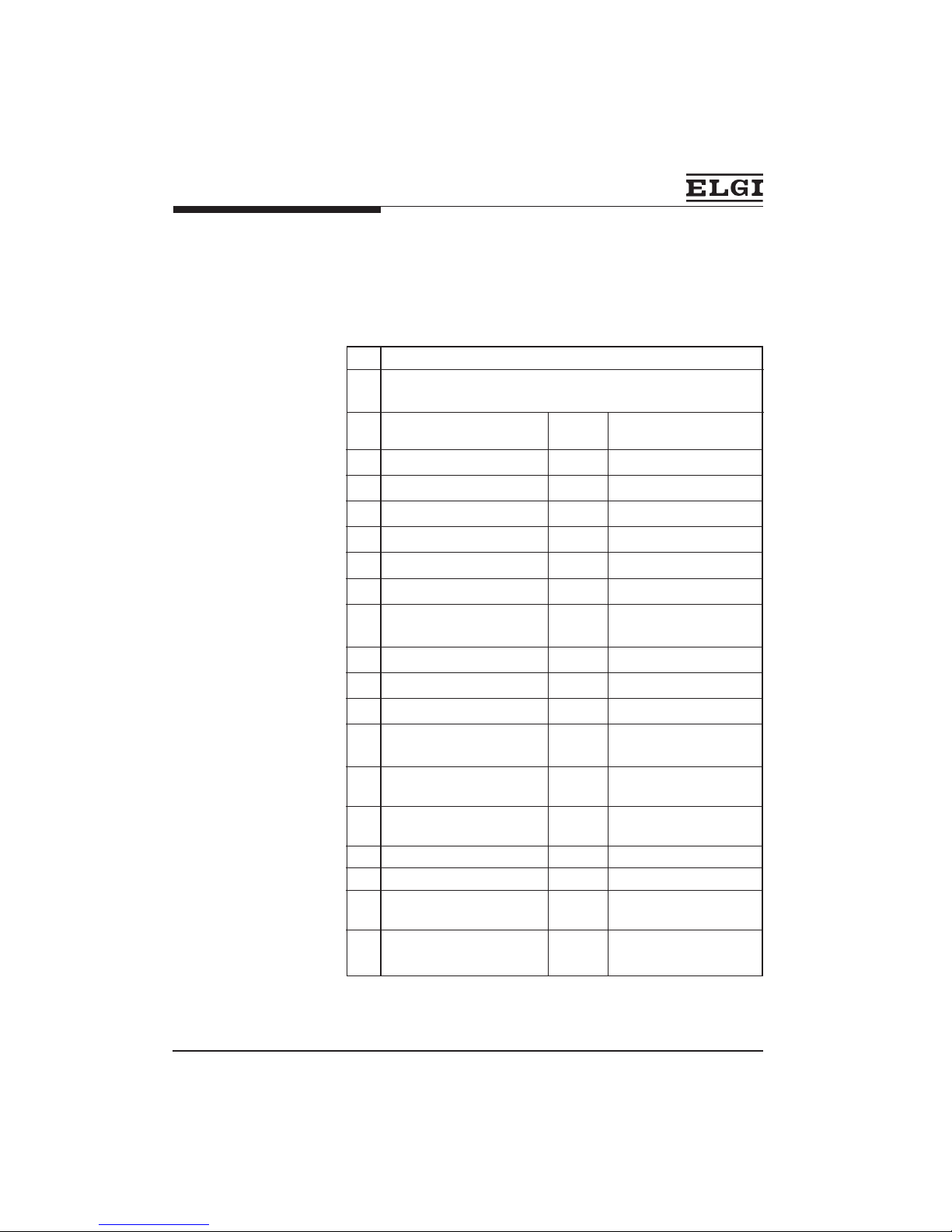
Technical Specifications
03 Working pressure kgf/cm
2
10.5
04 Displacement m3/h 78.48
cfm 46.19
lpm 1308
05 Free air delivery m3/h 60.00
cfm 35.32
lpm 1000
06 Cylinder size & stroke
length mm 100 x 60 x 100 : 85mm
07 No. of stages No. 2
08 Compressor speed rpm 980
09 Type of valve Disc valve
10 Direction of rotation Anticlockwise as viewed
from non-driving end
11 Type of drive Directly coupled with
motor by disc coupling
12 Crankcase oil capacity ml Min. 650
Max. 1880
13 Recommended oil Servo press 150
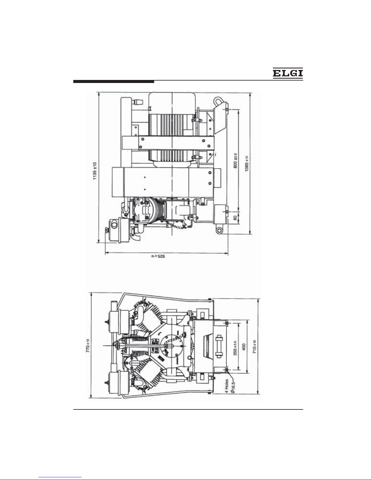
14 Nett weight kg 450±10
15 Overall dimensions mm 1135 x 770 x 925
LxBxH
16 Safety valve on intercooler
Opening pressure kg/cm
2
6
01 Model TRC 1000 MN UG
02 Type Reciprocating, Air cooled, ‘W’ type
and oil Splash lubricated
6
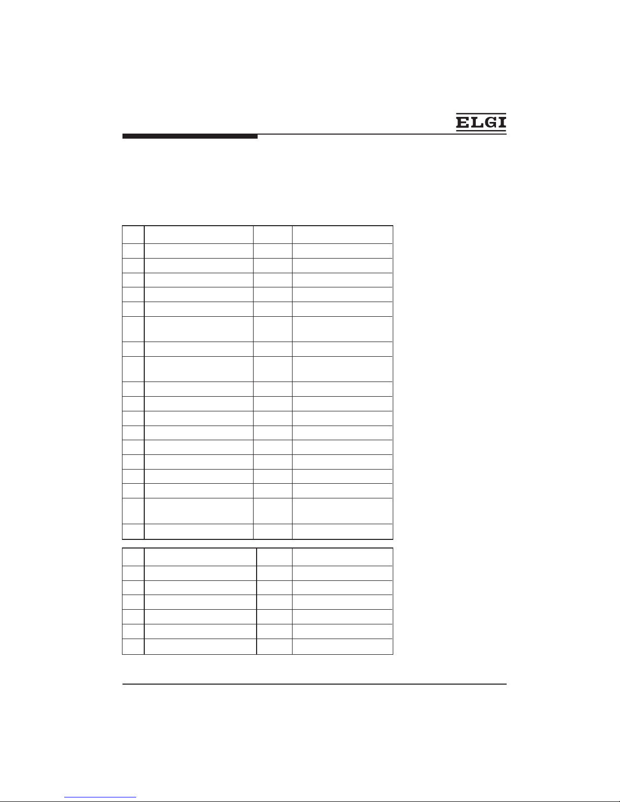
Technical Specifications
17 Coupling
Model Disc type coupling
18 Suction filter
a. Type Dry type
19 Motor Make
a. Make CROMPTON / BHARAT BIJILI
b. Type TEFC, Sqiurrel cage
induction
c. Power HP 14
d. Voltage Base voltage 415V
(290-500v)
e. Rated current Amp 24
f. No. of phases Three phase conn. in star
g. Frequency Hz 50
h. Enclosure IP 54
g. Insulation Class H
h. Speed rpm 975 / 970
i. Rating Continuous
j. Frame Size 180L / 180 L
k. Recommended grease Lithium base GR.3
SERVOGEM GR.3
L. Weight kg 200 / 205
20 Shaft & Bore size
a. Motor shaft mm Ø 48
b. Coupling bore(motor side) mm Ø 48
c. Fan flange bore mm Ø 48
d.Compressor shaft mm Ø 43
e. Coupling bore(Comp.side) mm Ø 43
f. Bore finish Ground
+0.018
+0.002
+0.021
+0.000
-0.03
-0.04
-0.030
-0.050
-0.005
-0.016
Unit
Unit

7
Technical Specifications
1 Cylinder bore mm Dia 100 Dia 60
2 Piston mm
3 Gudgeon pin size Dia 20 Dia 18
4 Clearance in cylinder Normal mm 0.15 - 0.16 0.06 - 0.09
Max mm 0.25 0.20
5 No. of plain compression rings 1 --
6 No. of stepped compression rings 2 --
7 No. of slotted oil control rings 2 --
8 No. of perma seal ring -- 2
9 No. of oil control three piece ring -- 2
10 Permissible piston rings ,
Permissible stepped rings ,
Permissible oil control rings ,
butt clearence Normal mm 0.08 to 0.25 --
Max. mm 0.40 --
11 Permisible perma seal piston ring butt
clearance 0.06 0.09
Permisible perma seal oil control ring
clearance 0.25 --
12 permissible piston rings side
play in groove Normal mm 0.04 to 0.08 0.024 to 0.074
Max. mm 0.12 0.1
13. Connecting rod small end needle
roller bearing internal diameter mm 20 18
14. Clearence between piston
Crown and disc valve mm 1.4 to 1.6 1.4 to 1.6
+0.01
0.00
Cylinder, Piston and Piston ring size
HPLPDescriptionSI.No
+0.01
0.00
0.000
-0.005
0.000
-0.005
Dia 99.835 Dia 99.855
Dia 59.941 Dia 59.915
8
General view of the compressor

9
Introduction
The Elgi air compressor model TRC 1000 MN UG is driven by an electric motor
by means of resillient flange coupling. It consists of three cylinders arranged
in a ‘W’ form on a crankcase. Dry type air filters are fitted to the suction side of
the LP cylinder heads. The discharge ports of the LP cylinder heads are
connected to the intercooler for effective cooling . Intercooler is connected to
the suction
port of HP cylinder head. The discharge port of the HP cylinder head is fitted
with a motor and mounted on a rigid, compact base. The air filters and other
pipe fittings are all clamped properly to arrest vibration. A fan with a fan guard
is provided to direct cool air on to the compressor unit. The fan draws the air
over the motor thereby cooling the motor also. An eye bolt used for lifting the
motor is provided at the terminal side of the motor. (Fix the eye bolt on top of
motor and lift the motor).
Crankcase
The crankcase is made of high grade cast iron an houses the crankshaft
assembly and cylinders. It act as the sump for lubricating oil and is provided
with a breather, drain plug and a dipstick assembly. The breather maintains a
partial vacuum in the crankcase to facilitate better lubrication.
Cylinder and cylinder head
The cylinders and cylinder heads are made of high grade cast iron and they
have close deep fins for effective cooling. The hardness of the cylinders is
closely controlled to ensure high wear resistance.
Connecting rod crankshaft assembly
The connecting rod and crankshaft assembly is precision machined and
dynamically balanced. The combined crankshaft with web is forged out of
carbon steel, hardened and precision ground. The crankshaft is provided with
single row heavy duty ball bearing at both ends. The main connecting rod big
end is provided with steel bearing rollers and small ends are provided with
needle roller bearings.
General Description

10
Piston and Piston rings
The pistons are of automotive type and made out of low expansion aluminium
alloy. They are provided with plain compression rings, stepped compression
rings and slotted oil control rings. The rings are made of special quality close
grained cast iron and designed for controlling wear and oil consumption to a
minimum. The gudgeon pins are of chrome steel case hardened and precision
ground.
Disc valves
Special type concentric disc valves have been used for suction and discharge
operations. The springs used are of high quality spring steel.
Intercooler, safety valve and aftercooler
The intercooler consists of a series of copper tubes, on which fins are wound
for effective cooling. It is mounted above the motor. It is provided with a safety
valve and a drain valve. The aftercooler is also made of copper tubes with fins
wound on them and arranged together for better cooling. A drain valve is
provided on the aftercooler.
Average Life
This type of coupling does not require any attention during running .
i. The coupling hubs will not require replacement earlier than six years of
continuous use.
ii. Misalignment if any in the coupling will reduce the life of the coupling
element.
General Description

11
The following points should be checked during commissioning.
a. Examine the unit for transit damages.
b. Position the compressor in the locomotive and check the level of the
compressor by using a spirit level.
c. Ensure that the compressor unit is properly aligned and all bed bolts
are fully tightened.
d. Rotate the compressor unit by hand and feel whether it is free, except
for compression forces.
e. Connect the motor to a three phase supply and ensure anticlockwise
rotation when viewed from the non-driving end of compressor.
f. Start up the unit and drain intercooler and aftercooler for a few minutes
and also ensure intercooler safety valve is free and functioning
properly.
g. Check if there is any abnormal noise or vibrations. If so, check up and
rectify the defect.
h. If all the above checks are satisfactory, the unit can be commissioned
for regular service.
Installation and operation
BEFORE COMMISSIONING THE COMPRESSOR
Fill up the crankcase with SERVO PRESS 150 oil upto the
maximum mark on the dipstick.
NOTE
12
General
Cleanliness and care must be observed whenever inspection and checks are
being carried out on the compressor and its accessories. For cleaning interior
parts, only rags which do not separate should be used. Cotton waste should
not be used. If any defect is noticed, it should be immediate attended to. The
unit should be properly maintained as per the undermentioned schedule.
Maintenance Schedule
The compressor should be run for a short while and
draining of the oil should be done when the oil is warm.
Do not use any cleaning agents to clean the interior, when
changing oil.
NOTE
Lubricating oil change should be carried out during
Recommended maintenance schedule
Recommended lubricating oil; Servo press 150
WARNING
During trip schedule
a. Clean the compresor thoroughly.
b. Check the oil level in the crankcase. Replenish with the correct grade of
oil if required.
c. Drain the intercooler and aftercooler in order remove the moisture
collected in them. Run the compressor for a few mintues with the drain
valve open, so that the moisture will be removed completely
During trip IA schedule
Check the compressor for satisfactory operation which include :
a. Cleanliness of the compressor.
b. Operational noise and vibration.
c. Tightness of mounting bolts and other fasteners.

13
d. Air leaks at the pipe joints and safety valve.
e. Clean the suction filter element thoroughly by using air from inside to
outside.
f. Check the suction and discharge operations and general performance of
the compressor.
g. Drain the intercooler and aftercooler.
NOTE :
RECOMMENDED GREASE
l SERVOGEM Gr.3 FOR BHARAT BIJILI MOTOR
l LITHIUM BASE Gr.3 FOR CROMPTION MOTOR
During IB schedule
a. All check points indicated under IA schedule to be carried out.
b. Breather valve should be dismantled, cleaned and checked for perfect
seating of the valve.
c. Check the safety valve setting.
d. Visually check the disc coupling for any abnormality in disc back
e. Check the oil level in the crankcase and topup the required quantity of oil
During IC, Schedule
a. All check points indicated under IA, schedule to be carried out.
b. Remove all the disc valves by removing the cylinder heads.
The valves are to be replaced with readily available spare valves since
valves that are removed should undergo thorough cleaning etc.
Maintenance Schedule

14
c. Dismantle the disc valves, check the springs, top plates and bottom plates.
There should not be any scratches or damage in the seating of valve
plates. If there is any damage, it should be lapped. If the springs are
damaged, they should be replaced. All the parts should be decarbonised
and thoroughly cleaned in kerosene. Reassemble the valve and assemble
it to the cylinder with new packings.
d. All the pipe lines should be checked for leaks at joints and packings
renewed as necessary.
During AoH Schedule
A general overhaul should be done. The compressor should be completely
stripped by experienced staff. All parts should be thoroughly cleaned,
examined and repaired in a clean surrounding.
Check the crankshaft assembly thoroughly. There should not be any shake in
the connecting rod about the crank pin. This can be checked by fixing the
crankshaft assembly between centres and shaking the connecting rod. Also
check the small end needle roller bearings. If there is any major repair, the
same may be attended to immediately.
Maintenance Schedule
1 Check oil level and top up, if required 45 Days 90 Days
2 Greasing of coupling 45 Days Eliminated
3 Intake air filter- Inspect element, clean if dirty 90 Days 180 Days
4 Inlet & Discharge Valve cleaning & Inspection 90 Days 180 Days
5 Drain and refill oil 90 Days 180 Days
6 Replace the Piston Rings, if required 540 Days 720 Days
(AOH -M18) (AOH-M24)
7 Replace all the Pistons, if required 720 Days 1080 Days
(IOH -M24) (IOH-M36)
8 Replace all the Cylinders, if required 720 Days 1080 Days
(IOH -M24) (IOH-M36)
Maintenance Schedule -Comparison between TRC1000MN and TRC1000MNUG
Maintenance
schedule for
TRC 1000 MN UG
Maintenance
schedule for
TRC 1000 MN
Maintenance Practice
SI
No.

15
General
Only a skilled technician who knows about the compressor should dismantle
and reassemble the compressor. Before dismantling the compressor, make
sure that it is free of compressed air. Pull the safety valve and ensure this.
Ensure that the electric power is disconnected from the unit.
Accessories
Remove the intercooler after removing the respective pipe fittings and bolts.
Remove the aftercooler and suction filters. Open the drain plug and drain the
oil from the crank case.
Cylinder head, Disc valves, Cylinder
Remove the cylinder head and take out the disc valve. Take care not to damage
the disc valves.While dismantling the disc valve, the position of the springs
should be carefully noted which will help during reassembling. Refer the
exploded view of the disc valve which is self explanatory. If damaged; the
springs should be replaced with new ones. Also check the packings and if
necessary replace by new ones.
Unscrew the cylinder and remove the cylinder. If the cylinders are tightly fixed
to the crankcase rotate the fly end hub. The cylinders will automatically come
up.
Piston assembly
Remove the circlip by using a criclip plier and gently knock out the gudgeon
pin. Inspect for scratces or slackness in the piston boss. If the pin is worn out
use a new pin. Remove the piston rings using a piston ring expander.
Clean the piston rings and the ring grooves in the piston. Measure the piston
size, gudgeon pin bore size, piston ring gaps at butts and side clearances.
Replace the rings as a set when limiting clearances have been reached.
Crankshaft assembly
Disassemble the disc coupling. Then remove the free and cover. Remove the
crankshaft assembly through the fly end cover bore along with the cover.
Using puller remove the fly end cover from the crankshaft assembly. Clean the
crankshaft and connecting rod assembly thoroughly in kerosene and dry with
compressed air. Inspect the bearings, if found damaged, replace them with
new ones.
Repairs

16
Crankshaft assembly
Remove the disc coupling. Then remove the free and cover. Remove the crank-
shaft assembly through the fly end cover bore along with the cover.
Using puller remove the fly end cover from the crankshaft assembly. Clean the
crankshaft and connecting rod assembly thoroughly in kerosene and dry with
compressed air. Inspect the bearings, if round damaged, replace them with
new ones.
Repairs
Bearing
Removing ball bearings from the crankshaft
Take a small steel wedge and gently hammer it keeping in between the
crankweb and the bearing.
Then use a suitable puller and take out the bearings.
Assembling the bearings on the crankshaft
Heat them to a temperature from 100C to 120C in an oil bath or on a hot plate
which is heated by a flame or electricity insert the bearings on the shaft so that
they will slide in and fit tight when cooled.
Assembling connecting rod and crankshaft assembly in the crankcase
Take the connecting rod and crankshaft assembly, clean it and oil the bearings.
Rotate the bearings by hand and check for any tightness. They should have
free rotation. Check whether the splasher pin is secured in position. The flat
sides of the splasher pin should be perpendicular to the axis of the shaft.
Fix the fly end cover on the crankshaft assembly. Insert the crankshaft assembly
through the flyend cover bore on the crankcase. Fix the free end cover on the
other side. Then fasten the end covers bolts uniformly.
17
1. Fit the motor side hub on motor shaft, fix key way grub screw
2. Assemble the coupling spacer on motor side coupling hub.
3. Put the motor on base frame first.
4. Put the compressor on base frame ensuring that the spacer encovers the
compress side hub and lamina screws get through the compressor side
hub flange tighten the compressor side hub to spacer bolts.
5. Locate the compressor properly and tighten it to the base (this is not to be
disturbed further)
6. Maintain 101mm distance (flange to flange) by moving motor towers or
away from compressors
7. Once 101 mm is maintained. Fix the motor to the base frame firmly.
8. Mount dial gauge on compressor side hub so that one dial gauge touches
motor side hub radially and other dial touches fan blade coller (
Ø 300)
axially (ensure dial gauge pressure by 2 bar)
9. Adjust ‘0’ on both dials at the top position (i.e., 12’O’ clock position)
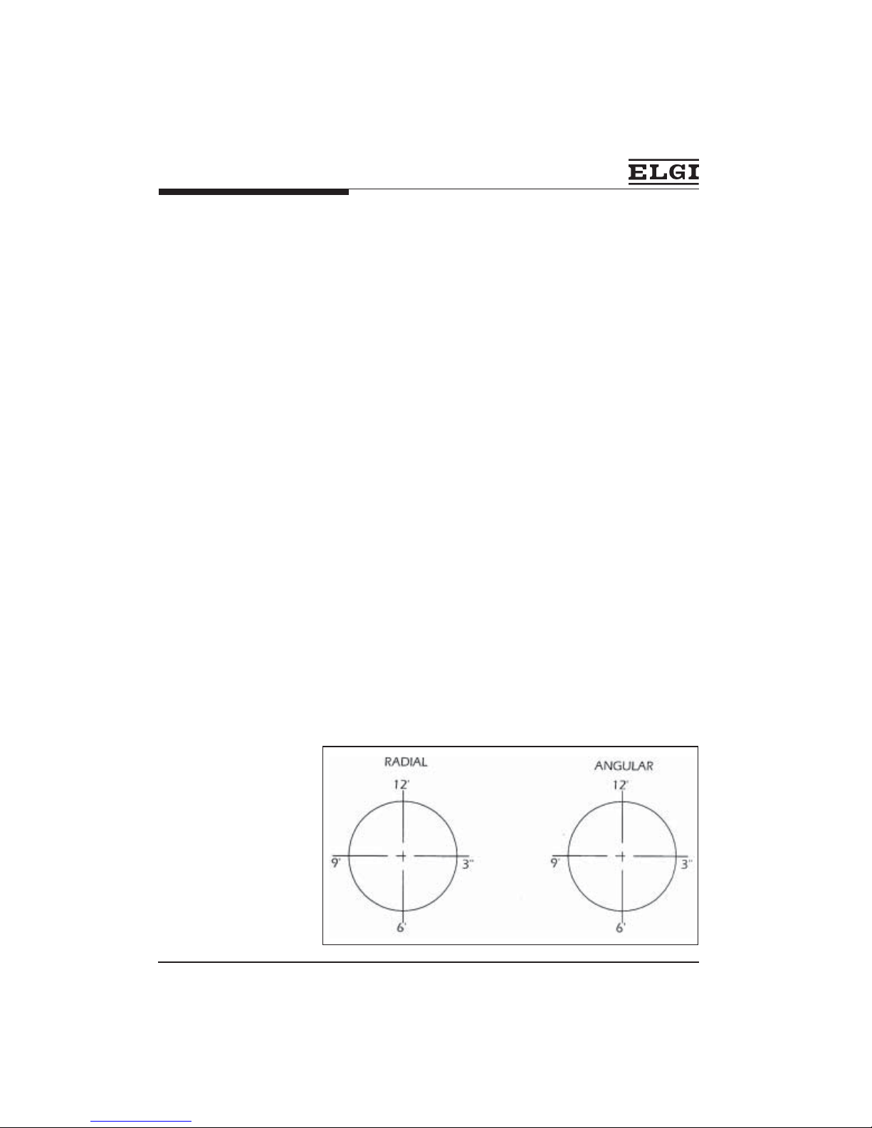
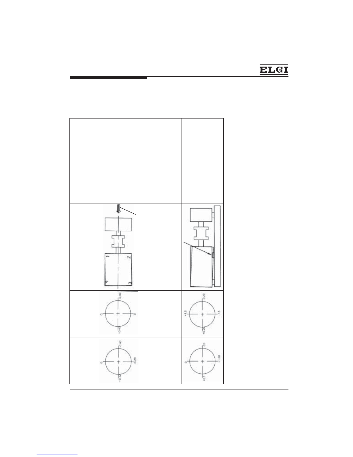
10. Take radial / angular readings at 12, 3, 6, 9 ‘O’ clock position record as
follows
11. Sample reading for interpretation - radial allowable limit - 0.85 mm (TIR)
Disc coupling assembly procedure
18
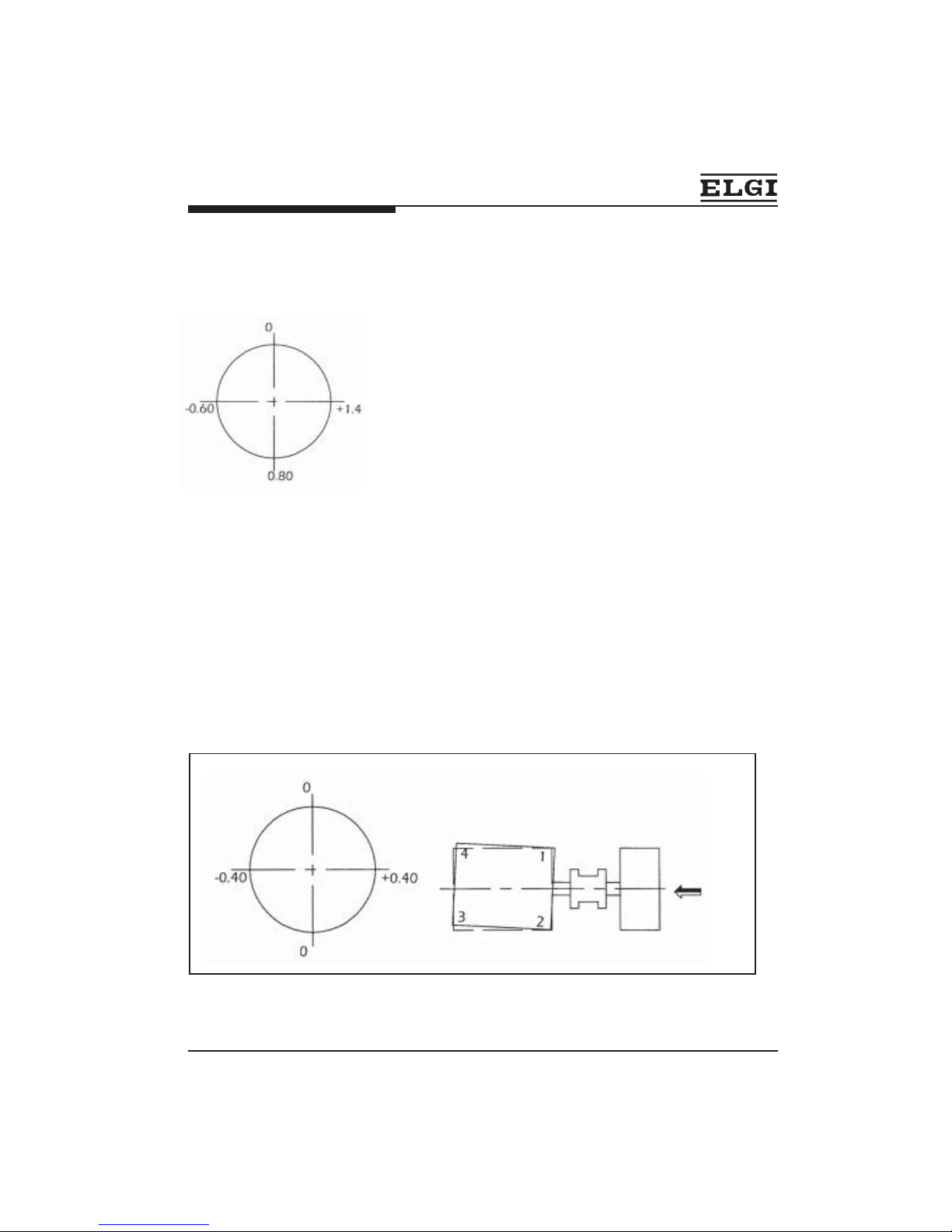
Disc coupling assembly procedure
INTERPRETATION
These reading confirm the following
1. Motor axis lower than compressor
axis by 0.80 (TIR) i.e., by 0.40 radially
2. Motor is shifted radially by 1.4mm
(TIR)
CORRECTIVE ACTION
a. To adjust the vertical shift (0.8), loose motor foundation bolts add 0.4mm
shims bellow all 4 legs of motor
b. To adjust the horizontal shift [-0.6+(+1.4)=2.0mm] shift motor by side
screws towers left, by keeping a close watch on dial gauge reading till
dial gauge reading reduce to +0.4
c. After above activities, tighten the motor foundation bolts fully, and again
take dial gauge reading for radial.
d. The allowable limit for radial is 0.85 (TIR) as such plaese follow above
procedure till the reading are within limits.
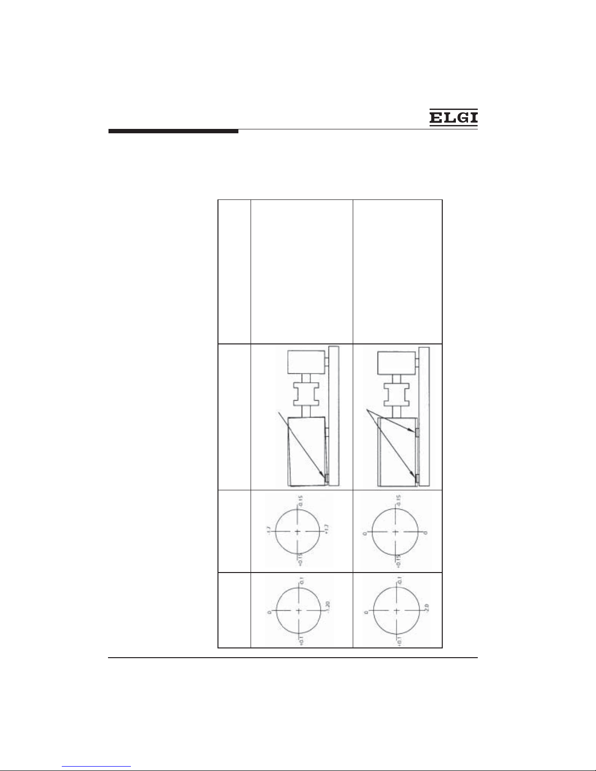
13. Sample reading for interpretation - angular.
Reading taken
from this view
Allowable limit - 1.7mm (TIR) at
Ø 300
This reading confirm the following motor is
tilted as per figure bellow
19
Disc coupling model assy instructions
CORRECTIVE ACTION
a. It’s required to rotate the motor towards left by keeping the bolt no ‘1’
fixed, loosing bolt no 2,3&4 and by pushing the side screw at bolt
number 4.
b. Shift motor by side screws towers left by keeping a close watch on dial
gauge reading till dial gauge reading.
c. After above activities, tighten the motor foundation bolts fully, and agian
take dial gauge reading for angular.
d. The allowable limit for radial is 1.7mm at
Ø 300 (TIR) as such please
follow above procedure till the reading are within limits.
e. Once axial /angular/radial readings are brought within tolerances (i.e.,
25% of the tolerance mentioned on the coupling drawing) fix all the
foundation bolt and tighten all coupling bolts to the required
torque (33 N-m).
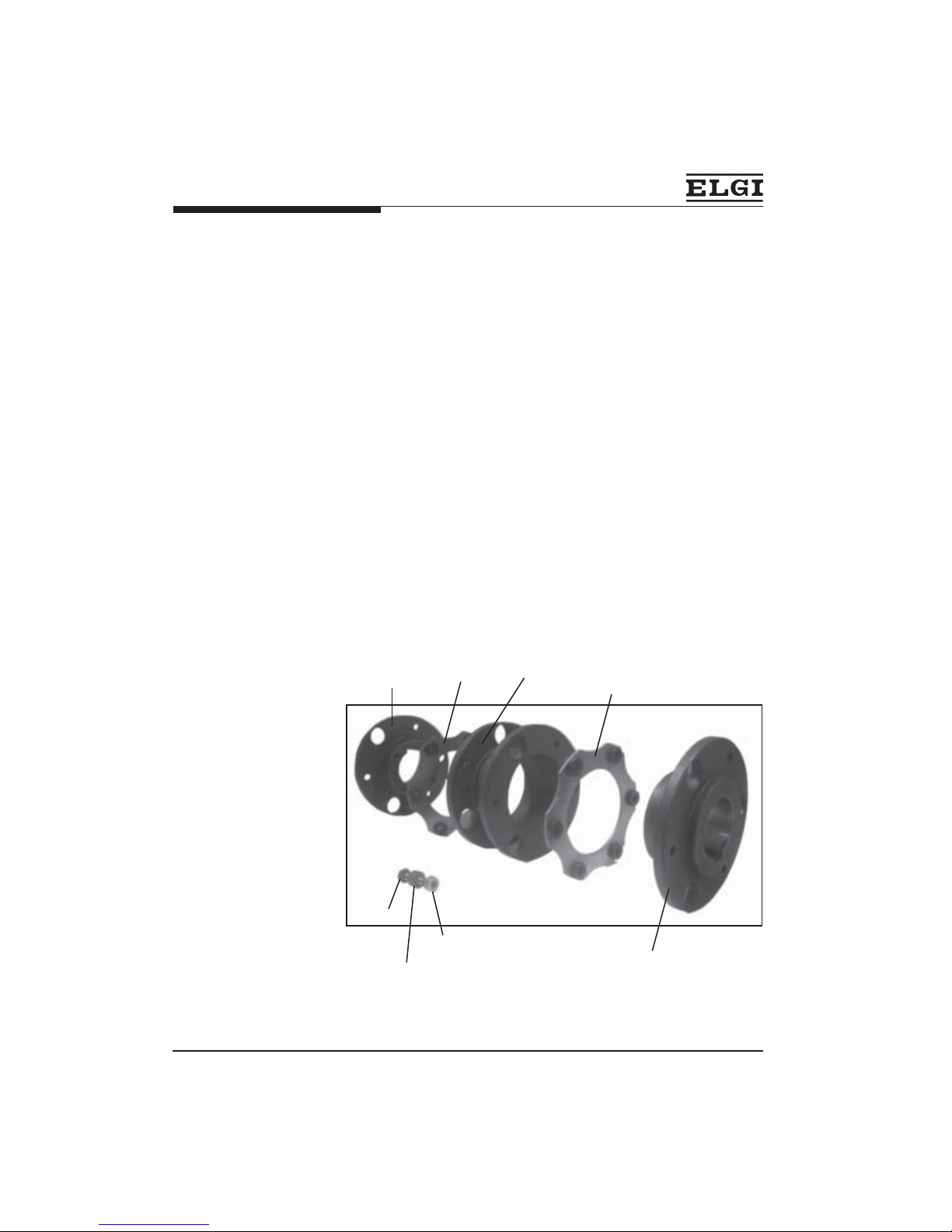
Hub motor side
Disc pack
SpacerDisc pack
Hub compressor side
Hex nut
Hex bolt
Over load washer
20
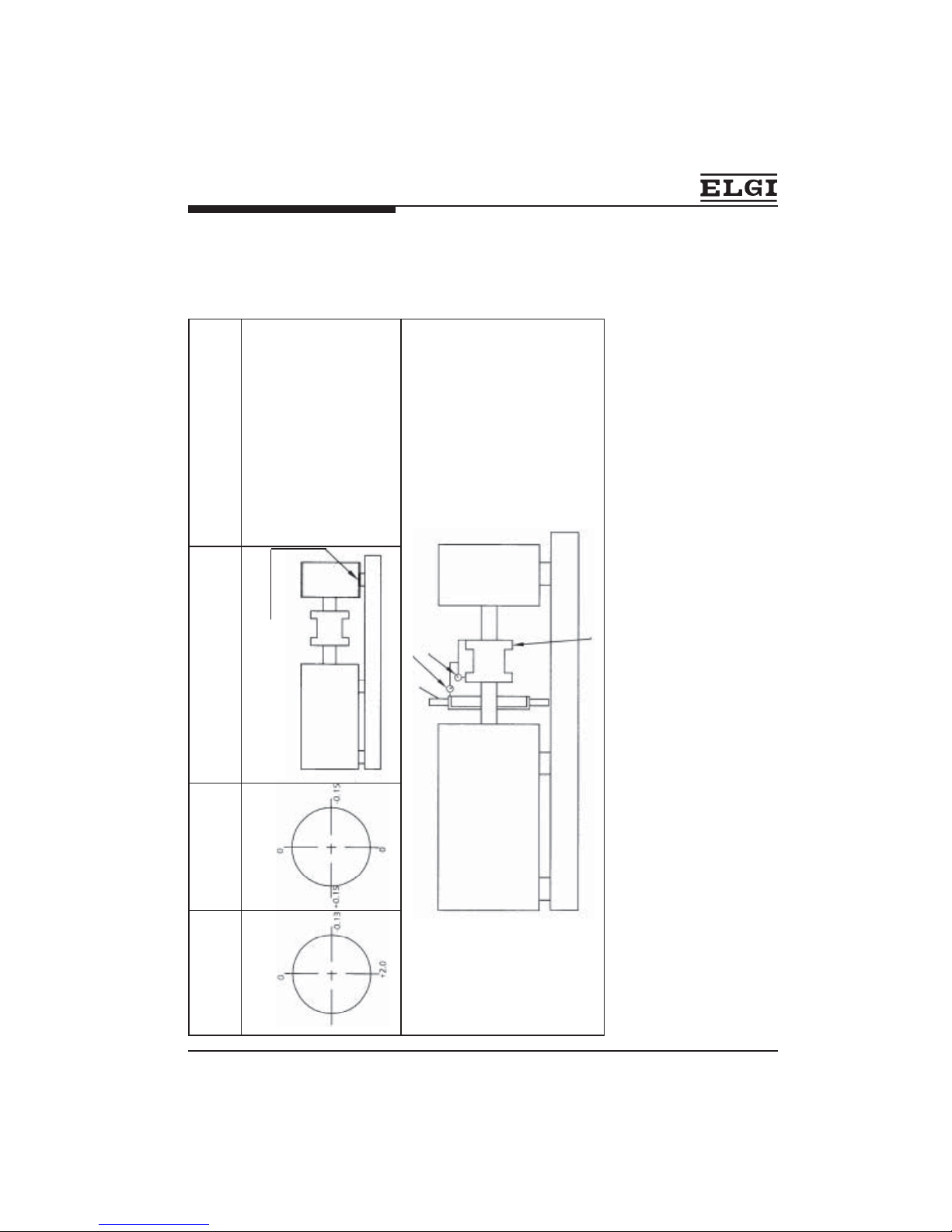
Radial sample
readings
Angular sample
readings
Motor position as per radial
reading
Remarks
Reading taken
from this view
CORRECTIVE ACTION
1. Vertical shift (0.2 TIR) is within the limit
no need to add shims.
2. Horizontal shift within the limit
[+0.12+(-0.4)=0.52mm] still you can
adjust the misalignment. To adjust shift
motor by side screws towers right, by
keeping a close watch on dial gauge
reading till dial gauge reading reduces
to +0.26
3. To adjust the angular shift it’s required
to rotate the motor towards left by
keeping the bolt no ‘2’ fixed, loosing
bolt no1,3&4 and by pushing the side
screw at bolt number 3, keeping a close
watch on dial gauge reading till dial
gauge reading reduces to ‘0’.
Add shim here
1. To adjust angular (1.5) and radial shift
(1.8 TIR), add shims at front foot.
21
1. To adjust angular (1.7) and radial
shift (1.2 TIR), add shims at rear
foot.
Radial sample
readings
Angular sample
readings
Motor position as per radial
reading
Remarks
add shim here
add shim here
1. To adjust radial shift (2.0 TIR),add
0.5 shims at front and rear foot.
22
1. To adjust radial shift (2.0 TIR),
add 0.5 shims at compressor rear
foot.
Disc coupling model assy instructions
Radial sample
readings
Angular sample
readings
Motor position as per radial
reading
Remarks
+0.1
add shim here
FAN
MOTOR
COMPRESSOR
COUPLING
DIAL GAUGE TO MEASURE ANGULAR READING
DIAL TO MEASURE RADIAL READING
Dial gauge mounting arrangement
23
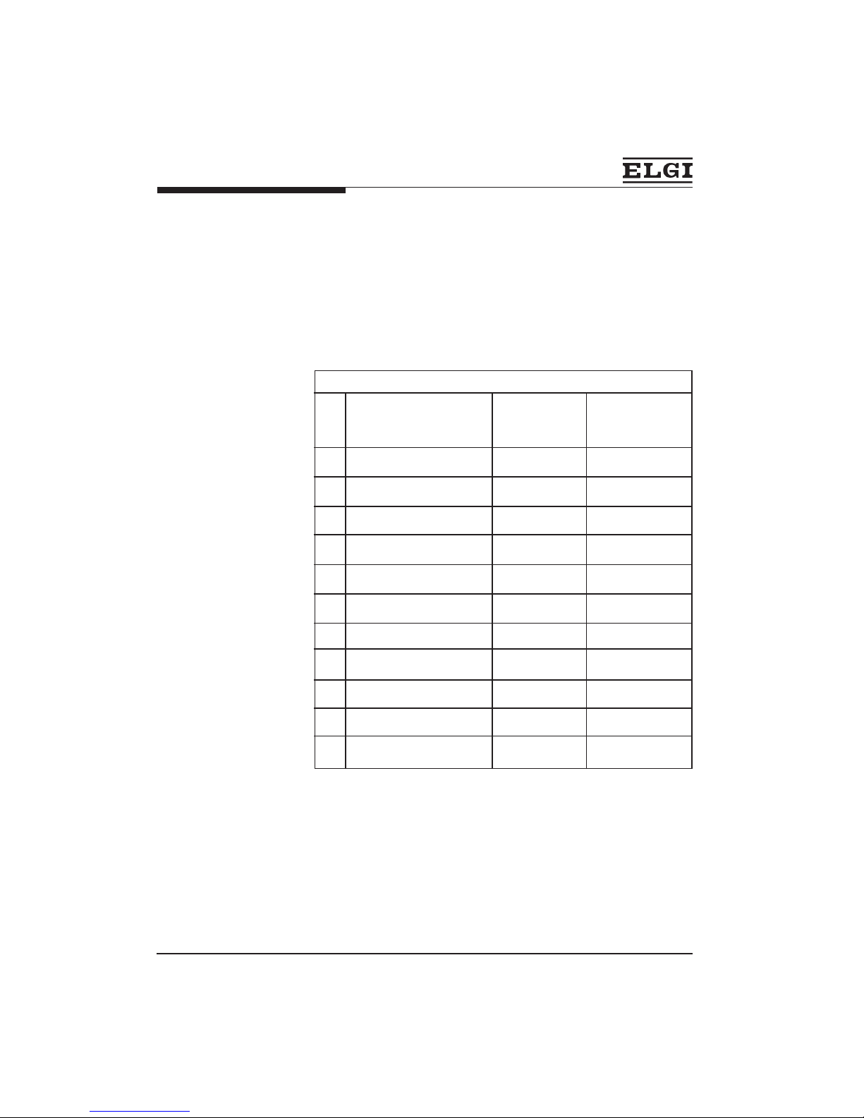
The following chart gives the tightening for various fasteners used in the
compressor.
SI.
No.
Location Thread size
Tightening
torque Values are
in N-m
1. End cover Free-end M8 30 N-m
2. End cover Fly-end M8 30 N-m
3. Crankcase to base M12 50 N-m
4. Motor to base M12 50 N-m
5. Crankcase to Cylinder M12 50 N-m
6. Cylinder to head M12 50 N-m
7. Pipe flange joints M12 50 N-m
8. Pipe flange joints M10 30 N-m
9. Disc coupling bolt M8 33 N-m
10. Drain plug 3/8" BSP 30 N-m
11. Dipstick ½" BSP 35 N-m
Torque chart
Model : TRC 1000MN - UG
24
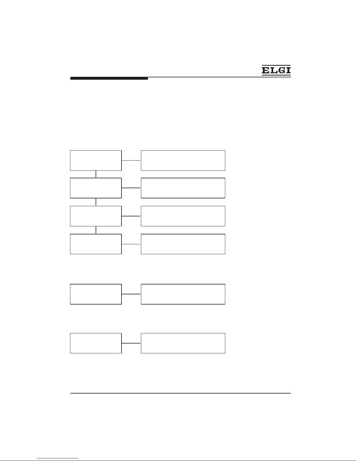
Troubleshooting
Problem : Pressure build time excessive
Check Remedy
Suction air filter is
clogged
Increase frequency of cleaning.
Pipe line leaking
Increase frequency with more level in
periodic check of oil.
Disc valves defective .
Carbon deposits too
much
Remove cylinder head and the disc
valves, decarbonisation
should be done.
Piston rings worn out
Check the ring gap, if required
change the rings.
Problem : Low pressure safety valve operates though the
specified pressure is not reached
Check Remedy
safety valve is not
functioning properly.
Check the safety valve components
for correctness & reset to
recommended rating.
Problem : LP safety valve operates during compressor
running
Check Remedy
Disc valve in the HP
cylinder not functioning
properly.
Check the disc valve components,
clean the dust if any and rectify the
defect.
ä ä ä
ä
ä
ä
ä
ä
ä
25
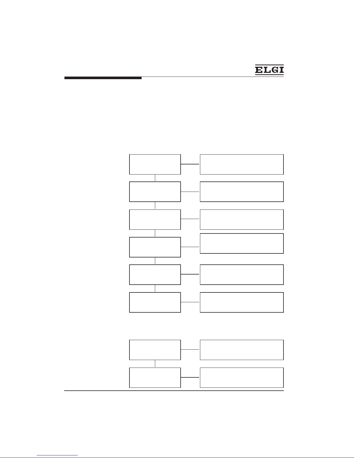
Troubleshooting
Problem : Abnormal noise and knocking of
compressor
Check Remedy
Connecting rod &
Crankshaft assembly
defective.
Journal bearings are
worm out.
Gudgeon pin loose in
piston
crankshaft assembly should be
reconditioned
Change the bearings.
Change piston and check for
lubrication
Disc valve is defective
Coupling is wornout
(Loose on the bore)
Key of the compressor
and motor loose.
Check and if necessary replace the
parts required.
Check the coupling hubs & change
if required.
Replace with correct size key.
Problem : Compressor overheating
Check Remedy
Dirty oil Oil, level low
Change oil, Fill correct grade of oil
upto maximum level. (SERVO 150)
Breather not working
Open, clean and refit after checking.
ä ä ä ä ä ä
ä
ä
ä
ä
ä
ä
ä
ä
 Loading...