

Page 1
Page 2

Page 3

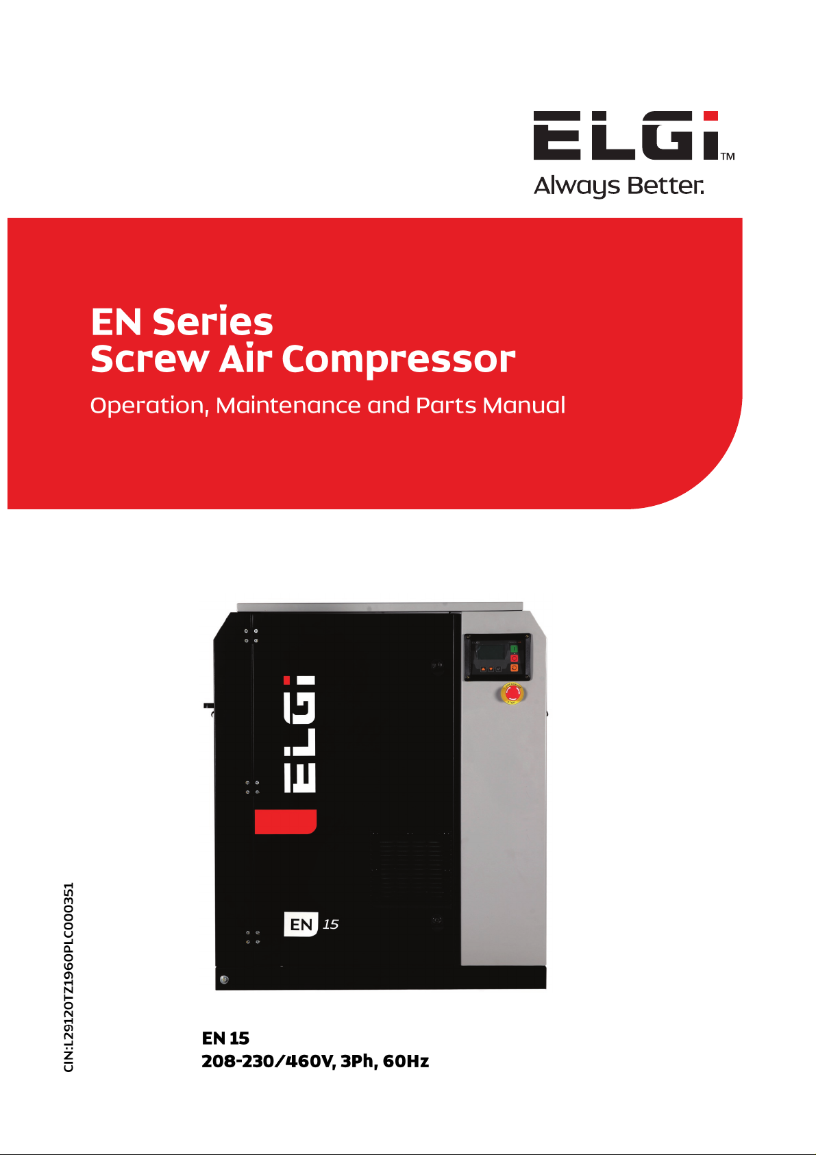
Product Manual
EN Series
Electric Powered Screw Air Compressor
EN 15 - 125
208-230/460V, 3Ph, 60Hz
Page 4

©
ELGI EQUIPMENTS LIMITED
Coimbatore, TN - 641 005
Part / Document No. 019000232
Contact Info:
ELGI EQUIPMENTS LIMITED
Coimbatore, TN - 641 005, India
Tel : 91 - 422 2589555
Fax : 91 - 422 2573697 (Domestic Business)
Fax : 91 - 422 2589401 (International Business)
E-mail : [email protected]
Website : www.elgi.com
Page 5

Machine Identification and Sale Record
Owner’s name /
Company name
: ………………………………………………………………………………………………………
………………………………………………………………………………………………………
Phone number : ………………………………………………………………………………………………………
Contact person : ………………………………………………………………………………………………………
E-Mail address/
Phone number
: ………………………………………………………………………………………………………
………………………………………………………………………………………………………
Model : ………………………………………………………………………………………………………
Fab. No. : ………………………………………………………………………………………………………
Year of manufacture : ………………………………………………………………………………………………………
Motor : ……………………………………………………………………………………………kW (HP)
Capacity : ……………………………………………………………………………………m
3
/min (cfm)
Rated pressure : ………………………………………………………………………………………bar.g (psi.g)
Date of delivery : ………………………………………………………………………………………………………
Date of commissioning : ………………………………………………………………………………………………………
Dealer name/address : ………………………………………………………………………………………………………
………………………………………………………………………………………………………
………………………………………………………………………………………………………
Dealer’s signature : ………………………………………………………………………………………………………
NOTE
The warranty on the compressor is valid only if all the details above are filled in and the dealer stamps and signs
this page. This report must reach the Regional Office/Head Office of ELGi within seven days of commissioning
date.
1.5
Page 6

Table of Contents
1.0 About ELGi 1.7
2.0 General functional description 2.1
3.0 GA drawing, P&I diagram 3.1
4.0 Specification sheet 4.1
5.0 Installation and operation 5.1
6.0 Maintenance 6.1
7.0 Controller 7.1
8.0 Drive system 8.2
9.0 Cooling system 9.1
10.0 Base and canopy system 10.1
11.0 Airend system 11.1
12.0 Spare kit details 12.1
13.0 Electrical drawings 13.1
14.0 Branch address 14.1
Chapter Page No.
1.6
Page 7

About ELGi 1.0
ELGi, established in 1960, designs and manufactures a wide range of air compressors. The company has gained its
reputation for design and manufacture of screw compressors through strategic partnerships and continuous research and
development. Over the years, it has emerged as a multi-product, multi-market enterprise providing total compressed air
solutions to all segments. ELGi’s design capabilities translated into a wide range of products ranging from oil-lubricated and
oil-free rotary screw compressors, reciprocating compressors and centrifugal compressors.
ELGi is one of the few companies in the world capable of manufacturing wide range of airends and compressor packages.
ELGi has most modern manufacturing facilities with high precision grinding machines, turning centres, CNC horizontal and
vertical machining centres and also the latest self measurement technology to maintain precise, aerospace manufacturing
tolerances. ELGi’s manufacturing plants are ISO and EOHS certified.
Over two million ELGi compressors are powering business in 70+ countries worldwide. The company offers a strong sales
and service network with a well-knit distribution network of dealers and distribution, worldwide. ELGi has its own
manufacturing operations in India, Italy and USA with subsidiary offices in Australia, Bangladesh, Brazil, China, Indonesia,
Italy, Malaysia, Middle East, Sri Lanka and Thailand. The company is fast expanding its global footprint, attracting
distributors and customers with its new generation products.
Need help…?
In India
You can contact ELGi customer care system (ECCS) to take care of customer complaints. The ELGi CCS works for six days a
week from 08:30 to 21:30 IST (Monday to Saturday). The complaints can be logged by calling any of the following toll free
numbers or by e–mail.
Toll free : 1800 425 3544
Website : www.elgi.com
Before making service request for your compressor, keep ready the details printed on the name plate of the compressor and
machine identification and sale record of this manual. When ordering spare parts, refer to the lists provided in the parts
manual and identify the part number. Specify the part number and quantity, in addition to
the name plate details.
Refer “ELGi services” for more details about ECCS under chapter “Maintenance”.
1.7
Page 8

Page 9

2.1
General functional description
Contents
Page No.
2.1 Using the manual 2.2
2.1.1. Definitions and symbols 2.2
2.2 Introduction 2.3
2.3 Safety 2.4
2.3.1 Precautions during installation 2.4
2.3.2 Precautions during operation 2.5
2.3.3 Precautions during maintenance 2.7
2.4 Functional description 2.9
2.4.1 Air circuit 2.9
2.4.2 Oil circuit 2.9
2.4.3 Drive system 2.9
2.4.4 Control system 2.10
General functional description 2.0
Page 10
2.2
General functional description
This operation and maintenance manual has been
specially designed keeping the customer in mind so that
the person can get the most out of this EG compressor.
Before starting the compressor, it is requested that the
manual should be read thoroughly. It contains vital
information about installation, commissioning, operation
and useful tips on maintenance to keep the compressor
as good as new, year after year. The manual has been
prepared with utmost care to help you understand the
various systems of the compressor, along with
descriptions, information and illustrations.
Following chapters are provided to help operate the
compressor in its best way.
Safety - safety precautions that must be followed while
using the compressor.
Technical specifications - technical details about the
compressor.
Installation and commissioning - all site
requirements, procedures to be followed during
installation, commissioning, preservation etc.
Functional description – parts, their function and
working.
Operating instructions – to operate the compressor
properly.
Maintenance – how to do the maintenance for the
compressor and their intervals.
Troubleshooting – identification and solving the
problems.
Decommissioning – how to decommission the
compressor, its disposal etc.
ELGi services – services from ELGi: CCS, air audit,
spare parts
Appendix – conversion tables, torque values, service
log book
Refer to the parts manual to identify the part number of
the required spare. Mention the Fab number, model and
part number while ordering.
This manual must be made available to the
compressor operating and maintenance personnel at
all times.
2.1.1 Definitions and symbols
This information is related to your safety and also to prevent
any problems relevant to the equipments used. To help
recognize this information better, the symbols are illustrated
in section “safety”.
All the information, illustrations and specifications in this
manual are based on the latest product information at the
time of preparation of the manual. Product improvement is a
continuous process in ELGi. The details in this manual are
likely to change without notice and ELGi reserves the right to
incorporate such changes.
Using the manual 2.1
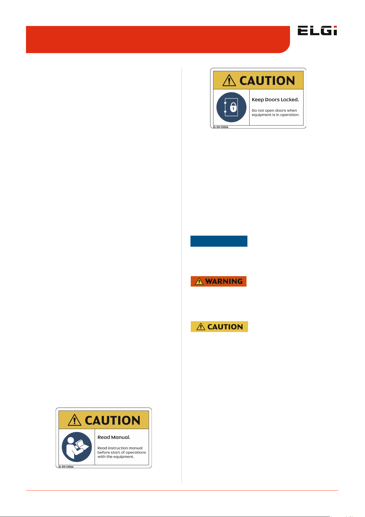
NOTE
Note clarifies procedures or conditions which may otherwise
be misinterpreted or overlooked. Note may also be used to
clarify apparently contradictory or confusing situations.
Warning calls attention to dangerous or hazardous conditions inherent to the operation, cleaning and maintenance
of the compressor which may result in fatal accident and
personal injury of the operator or other staff
Caution is to draw attention to a procedure which, if not
done correctly can lead to compressor damage.
Page 11

2.3
General functional description
Welcome to the ELGi customer family. ELGi compressors
are the source of compressed air in various segments
across the globe.
ELGi compressors are known for:
Greatest reliability
Fewer maintenance intervals
Ease of use
Highest safety
The ELGi screw compressor is designed to deliver:
High energy efficiency
Low maintenance cost
High discharge air quality
All the above factors assure a low life-cycle cost.
The rotors incorporate a specially designed eta-v profileELGi patented profile-which emphasizes on improving
reliability, performance, and efficiency. The Eta-v profile is
the latest and the most energy efficient profile in the
industry globally, assuring consistent performance during
the entire life of the compressor. ELGi screw air
compressors incorporate a compact design and
compressor run with low noise or vibrations. The capacity
control system ensures optimum air intake during startup, normal running, and unloading stages, minimizing
power consumption. The oil separation system ensures
that maximum oil is separated from compressed air,
ensuring the best air quality with very little oil carry-over.
Uptime
At ELGi, we are changing the way you look at compressed
air systems. It’s no longer just about delivering air. It’s
about delivering uptime. Our uptime design ensures that
the compressors run cooler, cleaner, and longer with
longer service intervals. The uptime components deliver
the best in quality and enable your compressor to run
smoothly, efficiently, and profitably. With uptime
assurance, we back our pledge, with industry-leading
warranties, parts availability, loaner compressors, and call
centres staffed by experts. We thank you for purchasing
an ELGi compressor and assure you the best service
during the entire life of the compressor.
EN SERIES
Your EN SERIES compressor belongs to a family of rotary
screw compressors from ELGI. The compressor has only
two moving parts - the rotors - which are separated by a
thin film of oil to prevent wear and increase compressor
reliability.
The screw compressor technology ensures that output
capacity does not diminish even after many years of
operation. It involves a continuous flow of air through
helical cavities in the screw so that compressed air
delivery is pulsation free.
EN SERIES compressors ship in a compact design and are
self-contained. The absence of reciprocating parts helps
the compressor run without noise or vibration. The
discharge temperature of the coolant oil is low, less than
195°F (90°C) under normal conditions, and therefore,
carbonized oil does not form in the compressor.
Salient Features
Two-stage air filter
Improved air filter life cycle
Noise-free package suitable for in-house operations
High volumetric efficiency
Efficient air-oil separation by OSBID (Oil Separation By
Impact and Deceleration)
Reliable fan that works even at high temperatures
Robust cooling system
Industrial designed canopy
Compact and hardly space-intensive
Split-type oil coolers for easy serviceability
Flush type panels for easy handling
Anti-vibration mounts for restricted vibration
Increased life of consumables
Zero-leak flanged joints.
Oil carry-over < 3 ppm
Advanced Neuron controller
Globally certified product - CE / UL and other country
specific approvals.
Introduction 2.2
Page 12
2.4
General functional description
The operator must follow the safe working practices,
instructions, procedures that this manual describes for
safe operation. The maintenance personnel must be
adequately trained, and have read and thoroughly
understood this ‘Operation and maintenance manual’.
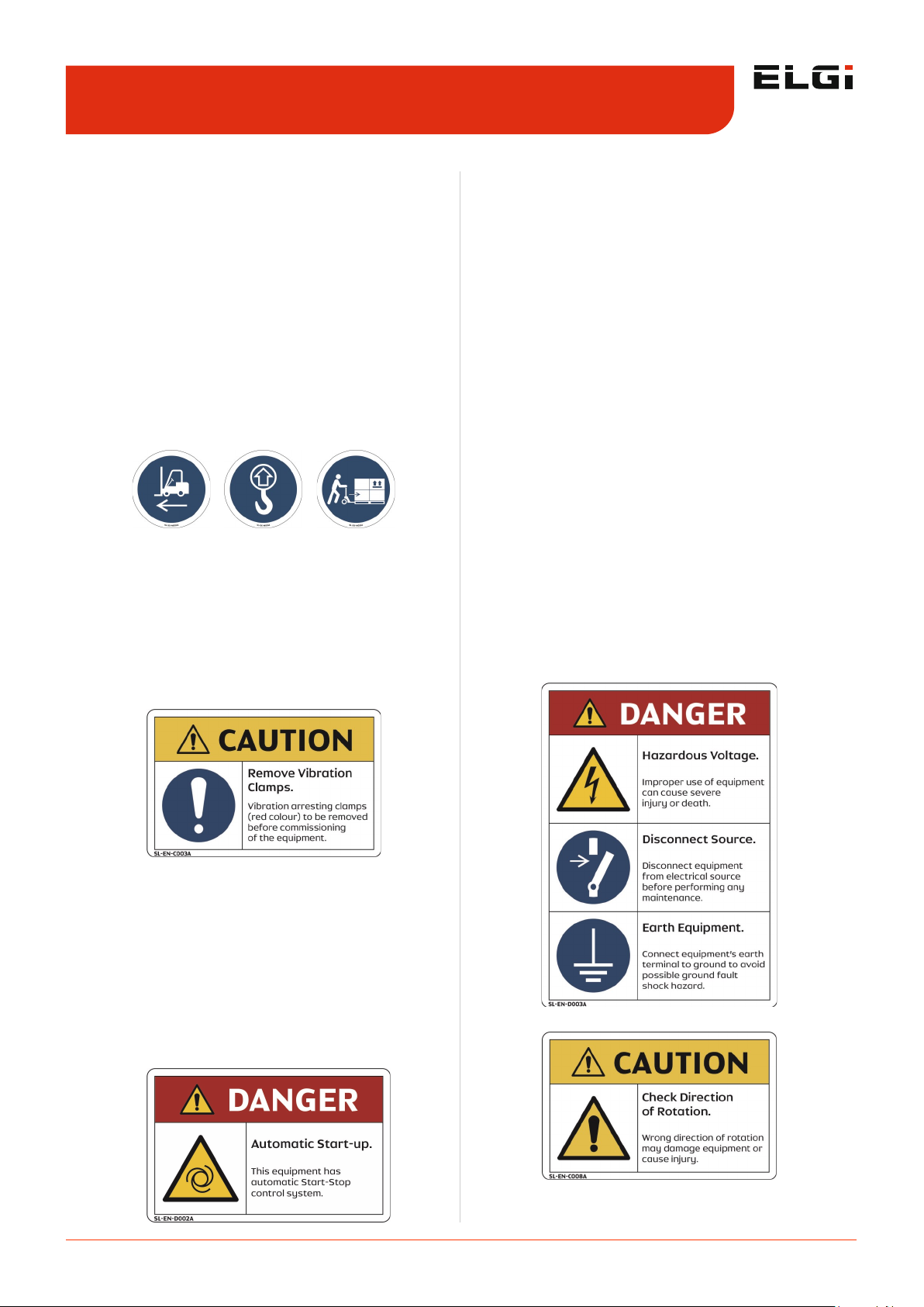
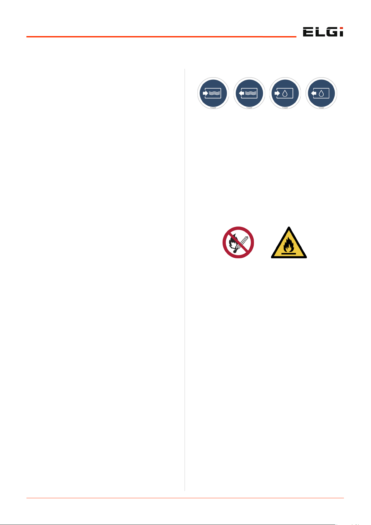
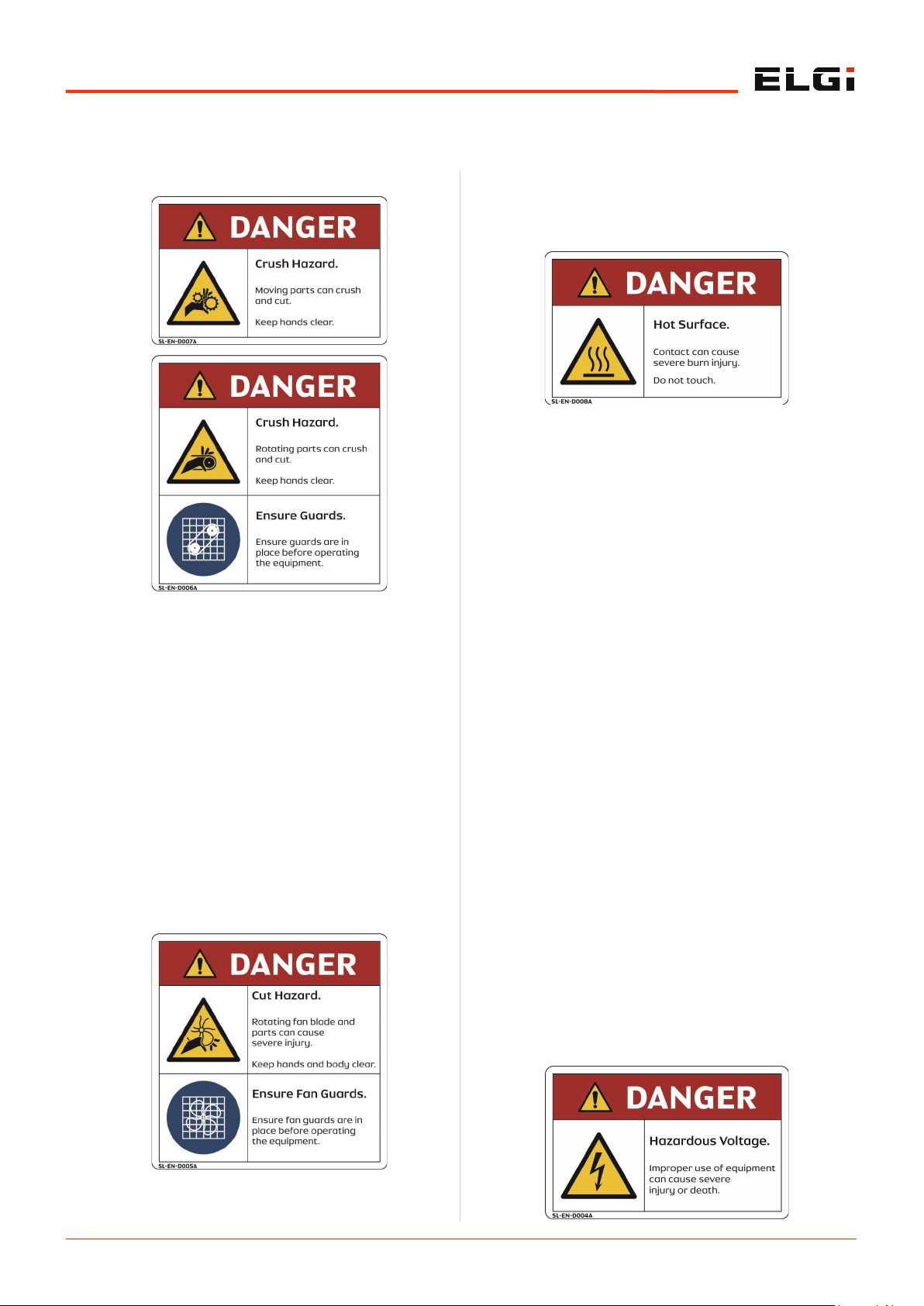
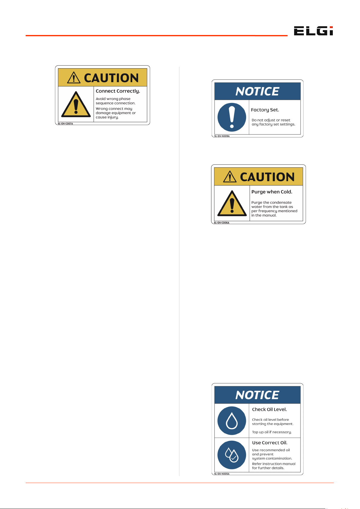
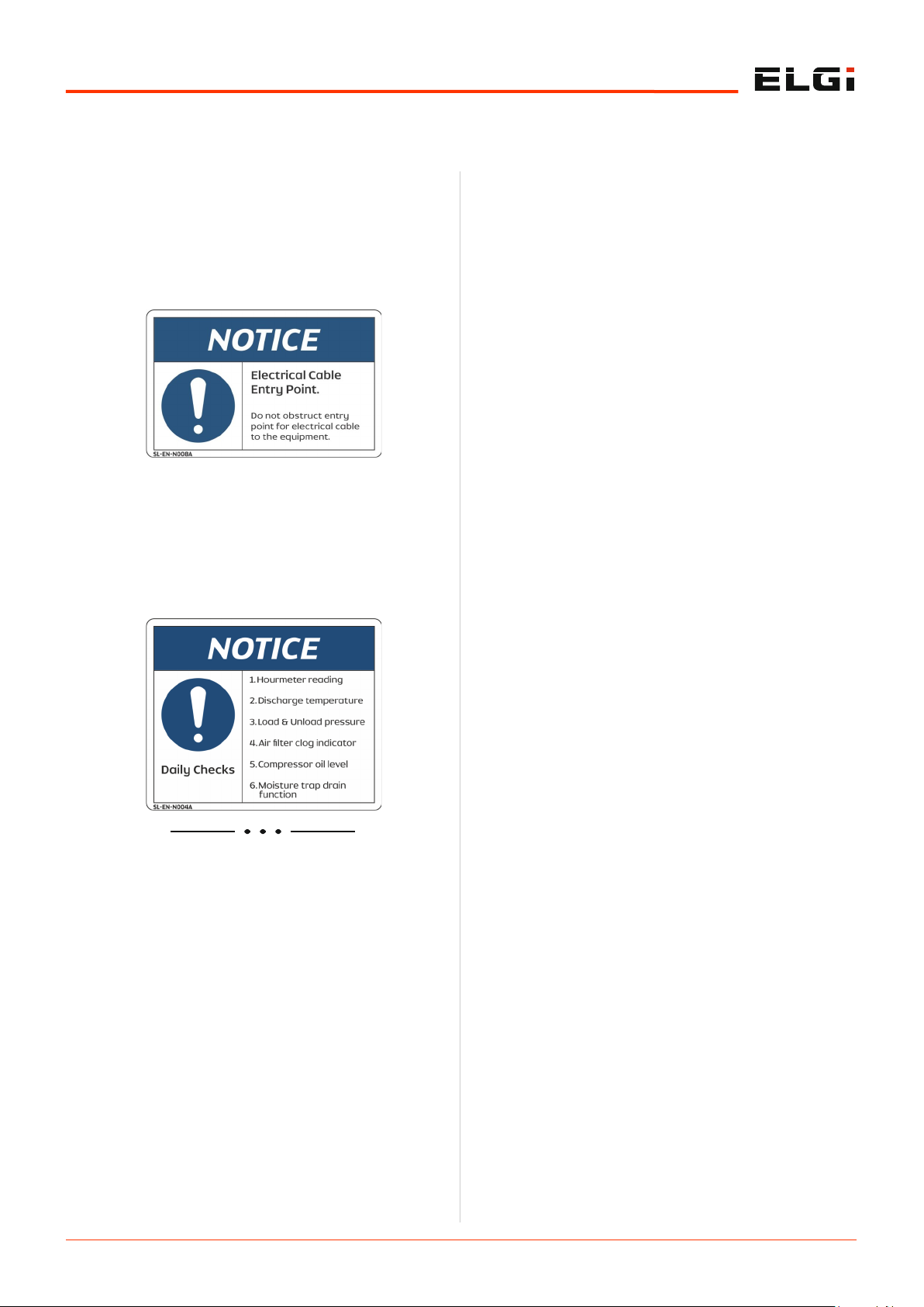
Decals are affixed at specific locations of the compressor
and they illustrate very important safety precautions.
2.3.1 Precautions during installation
Ensure that you fasten all loose parts before lifting. Select
the appropriate lifting equipment by considering the local
safety regulations, size and weight of the compressor.
Operate the lifting equipment carefully within the safe
operating limits. Ensure all necessary personal protective
equipment's (PPEs) is close at hand during this operation.
Maintain a cool and clean ambient for the compressor
and ensure that the air inlet is not obstructed. Make
arrangements to reduce the moisture entry through the
incoming air.
Remove protection such as caps, plugs, desiccant bags
before connecting the air line pipes.
Remove the red colored protective clamps from the
airend and motor while commissioning the compressor.
Do not use frayed, damaged or worn hoses. Distribution
pipes and connections must be of the correct size and
suitable for working pressure.
Make sure that the aspirated air by the compressor is
free of flammable fumes, vapors and particles, to
prevent internal fire or explosion.
For remotely controlled compressors and auto-start
compressors, provide a clear caution stating:
“DANGER” – Remotely controlled machine and will
start without notice
Ensure the operator is located far away from the intake
of the compressor.
Position the after-cooler discharge pipe in a way that it
is free to expand under heat and is not in contact with
or close to flammable materials.
Do not exert external force on the air outlet valve and
keep the connected pipe always free of strain.
Make available adequate cooling air must be made
available for the compressor particularly air cooled
compressors. Make sure that exhausted air does not
circulate back to the intake or cooling system.
Make the electrical connections according to the legal
standards and earth the compressor suitably. Provide a
sufficient number of fuses and other protective devices
to protect the compressor against short circuits. Good
practice is to provide an isolating switch nearby the
compressor.
Install manual valves behind non-return valves (NRV) to
isolate each compressor in multi-compressor systems.
Do not rely on NRV for isolating pressure systems.
Do not bypass, remove or adjust the safety devices or
other attachments residing on the compressor. Every
installed pressure vessel or auxiliary outside the
compressor should have pressure relieving device or
devices, as required.
Danger! Be aware that compressed air used for
breathing or food processing must meet O.S.H.A.
Safety 2.3
Page 13
2.5
General functional description
1910.134 or F.D.A. 21 C.F.R. 178.3570 regulations.
Failure to do so may cause severe injury or death.
Insulate or use protective guards to cover pipes or other
parts that may exceed 80ºC (176ºF). High-temperature
pipes must have a clear marking as potentially
dangerous.
Position the compressor on level surface. In case of
inclined surface, contact ELGi.
Do not allow compressed air to come in contact with
food and related items unless they are compressed airtreated specifically.
Be aware that this air compressor is intended for
generating only industrial-use compressed air.
2.3.2 Precautions during operations
When switching on remotely controlled compressors
ensure that no one is checking or working on the
compressor at that time.
Before starting, ensure that no tools or any loose parts
remain inside the compressor.
Do not operate the compressor if a possibility exists
that it could inhale flammable or toxic fumes, vapors or
particles.
Do not operate the compressor below or above its
operating limits.
Wear ear protectors if you work in an environment
where the sound pressure level reaches or exceeds 90
dB (A).
Keep all the compressor doors shut during operation.
For carrying out routine checks, the doors should open
only for short durations not more than 10 minutes.
Wear ear protectors when opening a door.
Keep hands, feet, floors, controls and walking surfaces
clean and free of water or other liquid to minimize the
possibility of slips and falls.
Pressure release
Know that annual servicing of the safety valve is
necessary. It should be checked at the prescribed
pressure for operation.
Use correct tools for maintenance and repair work.
Do not allow the manufacturers’ rated safe operating
pressure to exceed for pipes, valves, filters and other
fittings.
It is hazardous to point the compressed air directly
towards any personnel. Keep personnel out of the line
of the discharge air when opening hoses or other points
of compressed air discharge.
Use only the correct type and size of hose end fittings
and connections. When blowing through a hose or
airline ensure that the open end stays securely. A free
end will whip and may cause injury. Make sure to
depressurize a hose fully before disconnecting it.
Release all the pressure in the compressor system
before servicing or performing any maintenance
activity.
Do not engage in horseplay with air hoses. Serious
injury or death may result.
Do not use air at a pressure greater than 2.5 bar.g (36
psi.g) for cleaning purpose.
Open the oil fill cap only when the compressor is not
running and is not pressurized. Shut down the
compressor and bleed the receiver tank to zero internal
pressure before removing the cap.
Fire and explosion
Clean up spills of lubricants or other combustible
substances immediately.
Shut down the compressor and allow it to cool down
before checking or adding oil. Remove sparks, flames
and other sources of ignition away from the
compressor.
Do not permit smoking in the vicinity of the compressor.
Do not use flammable solvents for cleaning purposes.
Keep electrical wiring and other terminals in good
condition. Replace any wiring that has cracked, cut,
abraded or otherwise degraded insulation. Keep all
terminals clean and tight.
Keep grounded conductive objects such as tools away
from exposed live electrical parts like terminals to avoid
arcing, which might serve as a source.
Keep oily rags, trash, dry leaves, litter or other
combustibles out of and away from the compressor.
Do not operate the compressor without a proper flow of
cooling air or with an inadequate flow of lubricant or
with a degraded lubricant.
Do not attempt to operate the compressor in a
hazardous environment of any classification unless the
compressor has been specially designed and
manufactured for explosive applications.
Page 14
2.6
General functional description
Moving Parts
Rotating fan blades can cause serious injury. Disconnect
power supply before attempting service.
Keep compressor doors closed except when servicing or
during maintenance. The sound damping material on
the inner side of the compressor body should not be
removed or tampered with.
Wear snug-fitting clothing and tie long hair when
working around the compressor, especially when hot or
moving parts such as the cooler, the airend, the thermal
valve, the main motor or the fan motor are exposed.
Keep hands, arms and clothing away from couplings,
fans/belts and other moving parts.
Do not attempt to operate the compressor with the fan
guards, coupling guards/belt guards or other guards
removed.
Keep hands, feet, floor, controls and walking surfaces
clean and free of fluid, water or other liquids to
minimize the possibility of slips and falls.
Hot surfaces
Avoid bodily contact with hot oil and hot surfaces like
cooler, pipes etc.
Keep all parts of the body away from all points of air
discharge.
Keep a first aid kit handy. Seek medical assistance
promptly in case of injury. Do not ignore small cuts and
burns.
Toxic and irritating substances
Do not use air from the compressor for breathing.
Always wear safety equipment while operating the
compressor. Refer OSHA safety standards.
Do not allow compressed air to come into contact with
any edible items.
In the event of ingestion of oils, coolants or lubricants
used in the compressor, seek medical treatment
promptly. In case you come in contact with such
substances, wash with soap and water. Use MSDS for
oil to know more on this.
If warm cooling air from the compressor is being used
in air heating systems, e.g. to warm up a work room,
take precautions against air pollution and possible
contamination of the breathing air.
Electric shock
Keep all parts of the body and any handheld tools or
other conductive objects away from exposed live parts
of the electrical system.
Stand on a dry or insulating surface and do not contact
any other part of the compressor when making
adjustments or repairs to exposed live parts of the
electrical system.
Page 15
2.7
General functional description
Before switching on the compressor ensure that proper
earthing is done as per recommendation.
Make all adjustments or repairs with one hand. This
minimizes the risk of creating a current path through
the heart.
Conduct repairs only in a clean, dry, well-lit and
ventilated area.
Do not leave the compressor unattended with open
electrical enclosures. If necessary to do so, disconnect
the power to the compressor at the source and lock it
out so that power is not in advertently restored.
Disconnect, lock out, and tag the power source prior to
attempting repairs or adjustments, turning the
compressor manually or handling ungrounded
conductors.
All electrical installation must be in accordance with
recognized electrical codes and any local health & safety
codes.
Recognize that only authorized and qualified trained
personnel should carry out any electrical work on the
compressor.
Regularly check that all electrical connections are tight
and in good condition.
Periodically check whether
All guards are in place and securely fastened.
All hoses and pipes inside the compressor are in good
condition, secure and not rubbing against each other.
Any leaks exists.
All fasteners are tight.
All electrical leads are secure and in good order.
Safety valves and other pressure relief devices are not
obstructed by dirt or paint.
Air outlet valve, i.e. pipes, couplings, manifolds, valves,
hoses, etc. are in good repair, free of wear or abuse.
The air-oil tank is properly grounded.
2.3.3 Precautions during maintenance
Use safety glasses and incorporate safe working
practices before maintenance work.
Use appropriate tools for all maintenance works.
Use only genuine spare parts. Refer the section “Use
genuine spare parts” in “Maintenance” chapter.
Ensure that the compressor is cooled down before
maintenance is performed.
Springs under tension or compression store energy.
Uncontrolled release of this energy can cause serious
injury or death. Be cautious while performing the
maintenance of components loaded with springs (for
example minimum pressure valve, safety valve etc.).
Display a warning sign that says “Maintenance under
progress, don’t switch on” near the start switch.
Isolate the compressor from the air line (discharge) and
disconnect the power by opening and locking the
isolating switch before maintenance.
Prior to attempting repairs or adjustments, disconnect
the power at the source and verify at the compressor
that the circuits have de-energized. This minimizes the
possibility of accidental start-up or operation, especially
when the compressor is remotely controlled.
Open the oil filler cap only when the compressor is not
running and is not pressurized. Shut down the
compressor and bleed the receiver tank to zero internal
pressure before removing the cap.
Page 16
2.8
General functional description
If you are going to switch on remotely controlled
compressors must ensure that nobody is checking or
working on the compressor at that time. A warning sign
near the equipment’s start button is mandatory.
Wait up to five minutes to ensure that the air in the air-
oil separator tank is released to start routing
maintenance.
Vent all internal pressure prior to opening any line,
fitting, valve, drain plug, connection or other
components such as filters. Vent pressure by popping
up the safety valve.
Display a maintenance chart near the compressor to
easily identify the maintenance intervals of regular
service items.
Page 17
2.9
General functional description
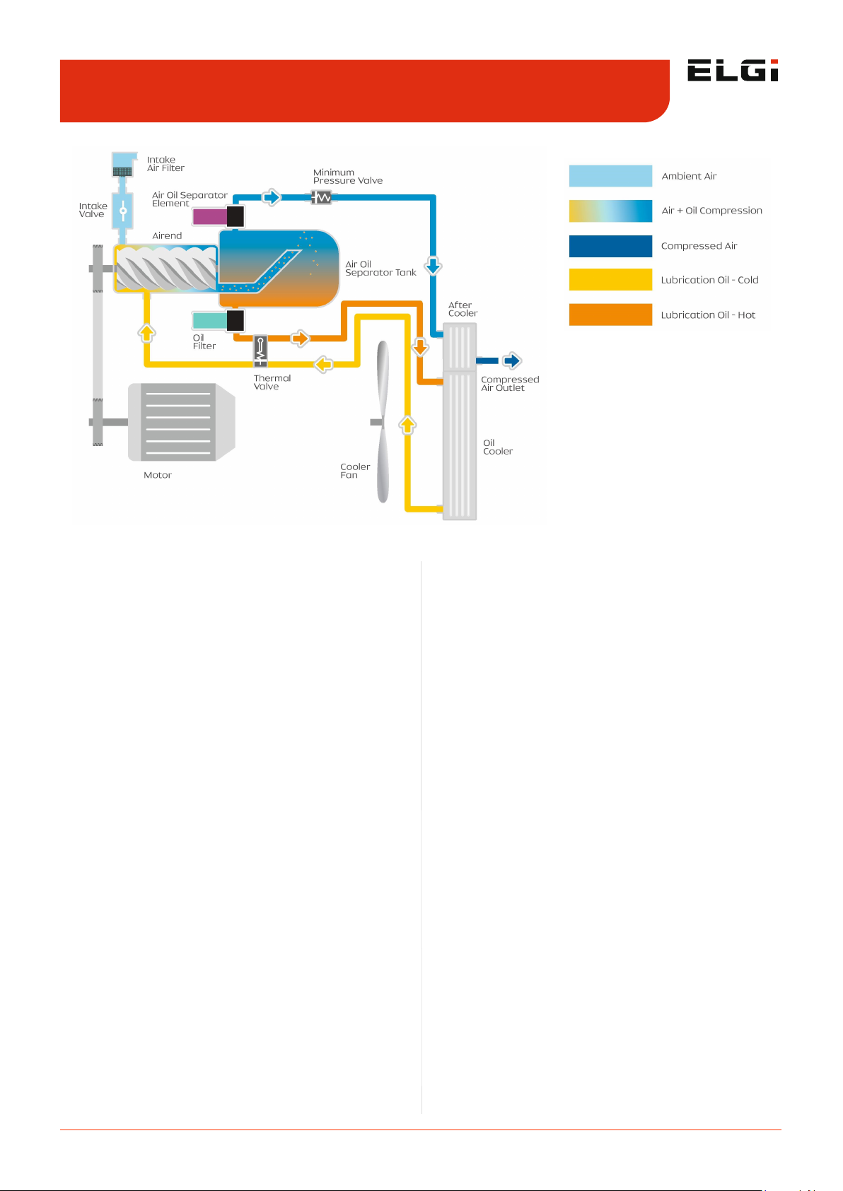
2.4.1 Air circuit
Atmospheric air enters into the airend through the air
intake system. The intake filters (pre filter and air filter)
prevent the entry of foreign particles (such as dust) into
the airend. Dust and micro particles above 10 microns are
separated by the pre filter and particles above 3 microns
are filtered off by the air filter. The intake valve regulates
the amount of air sucked into the airend. The opening and
closing of the intake valve is controlled by the pneumatic
pulse line actuated by the electrically controlled solenoid
valve.
The filtered air enters into the airend where it mixes with
the injected oil. The injected oil acts as a coolant to
maintain optimum temperature. It also seals the leaks
between the rotors and the housing and lubricates the
bearings and gears. The airend consists of two counterrotating intermeshed helical screws — the male and
female rotors — which are driven by an electric motor. The
air-oil mixture is trapped between the rotors of the airend
and is progressively compressed.
After being compressed, the air-oil mixture enters into the
air-oil separator tank, with high velocity, where it
undergoes a unique 3-stage separation process to remove
maximum oil content. This highly efficient 3-stage
separation process uses the impact velocity of the air-oil
mixture along with the OSBID process to make the
mixture very lean. The final stage of this separation
consists of passing the lean mixture through the air-oil
separator element to ensure an oil content of 3 ppm and
less in the air.
The oil separated and collected in this element is then
returned to the airend through the scavenging line. The air
passes through a minimum pressure valve (MPV). It
maintains a minimum differential pressure required for
circulation of oil within the compressor unit. The
compressed hot air is cooled in the after-cooler. .
2.4.2 Oil circuit
The separated oil in the air-oil separation tank flows into
the airend. The oil either diverts to the oil cooler or oil
filter or both depending upon the temperature. The
thermal valve governs and controls the oil flow path. The
oil before being injected into the airend is filtered. An
orifice residing in the oil flow path towards the airend
controls oil flow. Any small quantity of oil, separated and
stored in the separator element, enters into the airend
through the scavenging line. The whole oil circulation
circuit in the compressor is operated solely by the
differential pressure maintained by the minimum pressure
valve (MPV) and doesn't require any additional pump.
2.4.3 Drive system
The airend is powered by an electric induction motor
through a belt and pulley. When the compressor is turned
ON, the motor is started in star mode and it takes 6 to 9
seconds to change over to delta mode. During this period,
the intake valve closes and thus the motor starts without
load. In delta mode, the motor speed stabilizes, the
solenoid valve energizes after 10 seconds of changeover to
reduce motor load, the blow down valve closes, the intake
valve opens and the compressor starts loading. This
ensures very little starting load. Next, the intake valve
opens and the system starts building up pressure. Anti-
Functional description 2.4
Figure 1. Screw compressor systems - Schematic diagram
Page 18

2.10
General functional description
vibration mountings reside below the airend and the
motor. This configuration reduces the transmission of
vibration from both the airend and motor to the structure,
reducing noise and ensuring reliability of the parts
mounted on the structure.
2.4.4 Control system
Depending on the demand for compressed air from the
application at a particular time, the compressor needs to
respond accordingly. The compressor, therefore, operates
in either loading or unloading mode to meet this
requirement. The primary objective of these modes is to
save energy and reduce wear and tear on the machine.
The control system ensures a smooth start without
overloading the motor.
The compressor is started in star mode, during which
most of the compressed air is vented to the atmosphere.
This mechanism helps prevent overloading of the motor.
In delta mode, the motor speed stabilizes, the solenoid
valve energizes after 10 seconds of change-over to reduce
load on the motor, the blow-down valve closes, and the
compressor starts loading.
When the receiver pressure reaches the maximum limit, a
signal arrives at the solenoid valve from the control
system. Next, the inlet valve actuates and closes, and the
compressor runs in unloading mode. If unloading mode
continues for more than 5 minutes, i.e., no compressed
air is consumed and thus no decrease in pressure occurs,
the system stops and switches to standby mode. If a drop
in pressure occurs in the receiver, the compressor returns
to loading mode automatically.
Page 19
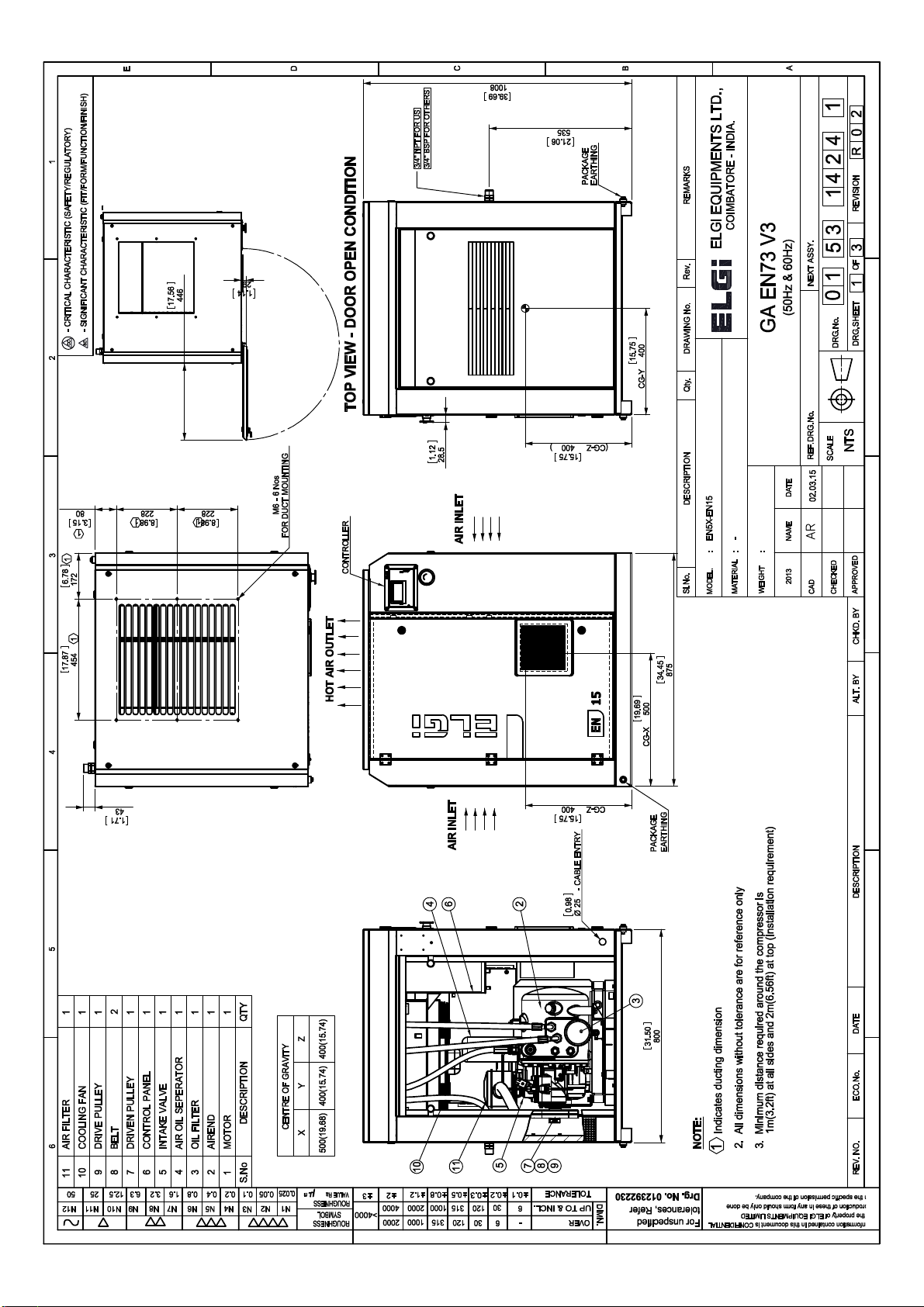
Page 20

M
LEGEND
M M
M
9
M
M
15
Page 21
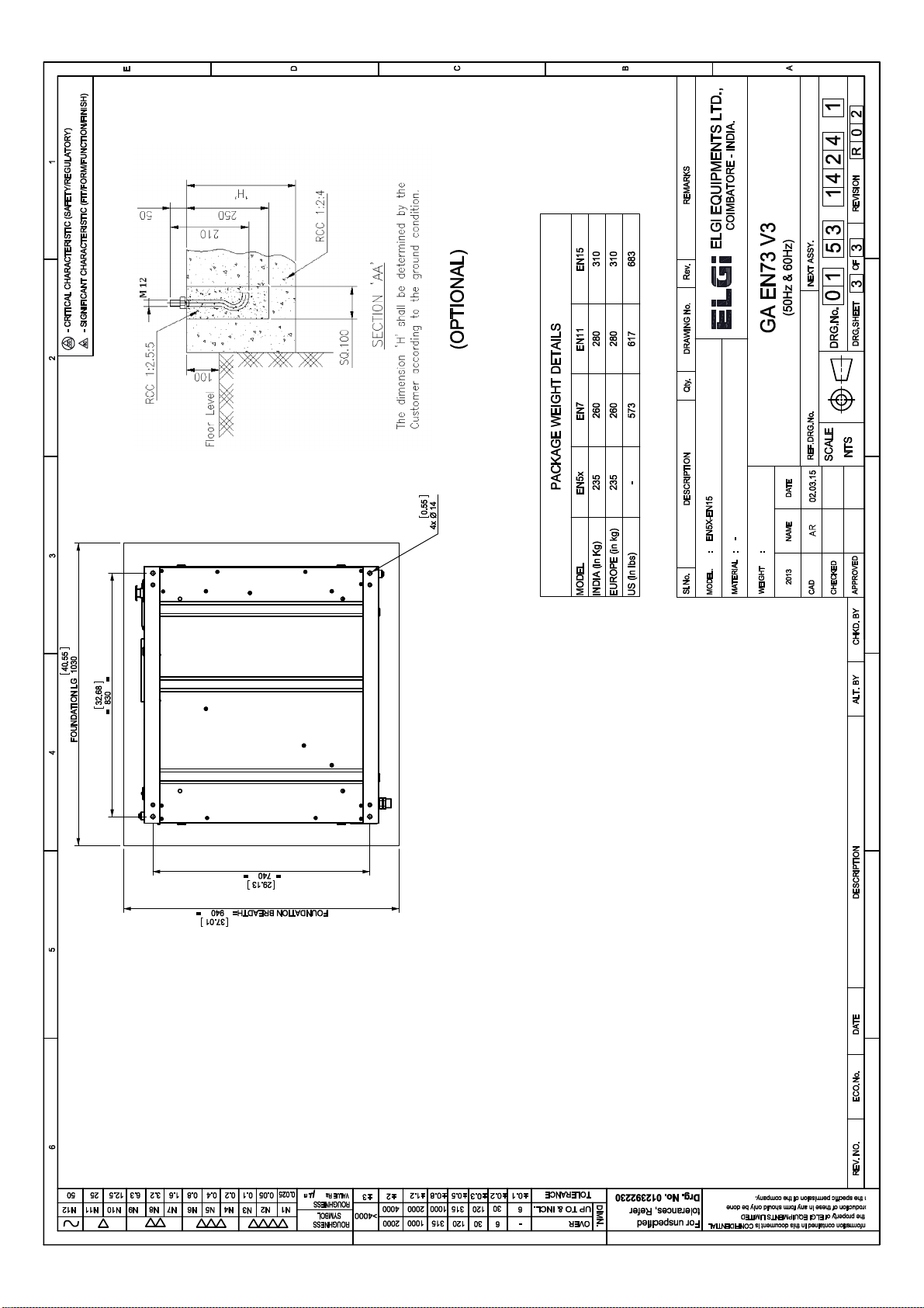
Page 22

4.1
Technical data
Standard
Model - EN 7 EN 11 EN 15
Working pressure psi.g 100 125 150 175 100 125 150 175 100 125 150 175
FAD - Free air delivery
cfm 42.5 38.5 34.0 30.0 64.0 55.0 51.5 45.0 81.5 68.0 61.5 58.0
m3/
min
1.20 1.09 0.96 0.85 1.81 1.56 1.46 1.27 2.31 1.93 1.74 1.64
Unloading pressure psi.g 104 129 154 179 104 129 154 179 104 129 154 179
Nominal power supply
conditions
- 208-230 / 460 (+/-10%), 60Hz (+/-5%), 3 phase
Main motor rating hp 10 15 20
Type of motors (main drive &
fan drive)
- Squirrel cage induction-TEFC
Insulation and protection of
main motor
- Class F/IP55
Frame size / mounting type - 215T/B3 254T/B3 256T/B3
Type of starter for main motor - DOL Star delta starter
Maximum fan motor rating per
fan X no. of fans
hp 0.127 x 1 0.375 x 1
Rated speed of fan motor rpm 3200 1560
Safety valve set pressure psi.g 205
Technical data 4.0
Page 23

5.1
Installation and operation
Contents Page No.
5.1. Installation and commissioning 5.2
5.1.1 Commissioning procedure 5.2
5.1.2 Unpacking 5.2
5.1.3 Handling the compressor 5.2
5.1.4 Site requirements 5.3
5.1.5 Ventilation and exhausting hot air 5.4
5.1.6 Electricals 5.4
5.1.7 Air pipe line 5.5
5.1.8 Oil filling procedure 5.7
5.1.9 Procedure for changing oil the compressor during service 5.7
5.1.10 Direction of rotation 5.8
5.2. Preservation for long idle storage 5.9
5.2.1 Airend 5.9
5.2.2 Motor 5.9
5.2.3 Air-oil separator tank 5.9
5.2.4 Disposal of Packing 5.9
5.3. Operating instructions 5.10
5.3.1 Safety system and interlocking Device 5.10
5.3.1.1 Discharge temperature sensor 5.10
5.3.1.2 Minimum pressure valve 5.10
5.3.1.3 Pressure relief valve 5.10
5.3.1.4 Overload relays for main motor and fan motor 5.10
5.3.2 Operation control system 5.10
5.3.3 starting the equipment 5.10
5.3.4 starting and normal operation mode 5.10
5.3.5 Unloading mode 5.10
5.3.6 Stopping 5.10
Installation and operation 5.0
Page 24
5.2
Installation and operation
5.1.1 Commissioning
Before you operate the new EN series compressor for the
first time, install it at your site according to ELGi’s
Installation specifications.
For safe operation of the compressor, the servicing
technician performs a series of checks on the compressor
and the systems to which the compressor connects. The
technician will explain to the compressor operator how to
operate and maintain the equipment. This procedure is
referred to as the commissioning process.
The commissioning of your compressor is a necessary
safety step. The general operating conditions of the
equipment, including the cleanliness of the ambient
atmosphere, the temperature and ventilation, are checked.
Technical details relating to your system, such as
particulars of your electrical installation, are verified. The
commissioning process includes familiarizing your
compressor operator with all aspects of the compressor’s
normal running and dealing with unusual situations.
Please make preparations according to the instructions
provided in the Installation section for your EN Series
compressor to be commissioned. Ensure that the location
chosen meets the requirements of accessibility,
ventilation, and safety. Provide electrical power as
recommended in the Installation section. Select air pipe
lines and receivers for your system according to the tables
provided in the same section.
After completing the commissioning process, the
technician will fill in the commissioning report and the
warranty card.
5.1.2 Unpacking
Unpack the compressor from the packing case by
removing the nails or pins. Unscrew the bolts as you hold
the compressor to the base of the crate.
Once you have separated the packing material, check the
contents against the packing list. The compressor ships
with the following items:
The key to doors
The operation and maintenance manual
A checklist of parts of the machine
An electrical drawing
Tools may be provided on request. If any components are
missing, contact ELGi immediately.
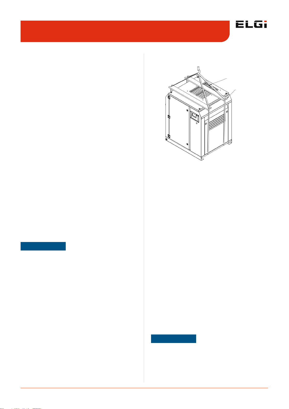
5.1.3 Handling
If the compressor consists of a lifting bail, then use only
the bail to lift the bail machine. If no bails exist, lift the
bail machine using slings. Always use slings and not the
lifting bail to airlift compressors by helicopter.
Prior to lifting, inspect the lifting bails and points of
attachment for cracked welds; for cracked, bent,
corroded or otherwise degraded members; and for loose
bolts and nuts.
Make sure the entire lifting, rigging, and supporting
structure has been inspected, is in good condition, and
has a rated capacity of at least the net weight of the
compressor. If you are unsure of the weight, then weigh
the compressor before lifting it.
Make sure the lifting hook has a functional safety latch,
or equivalent, and is fully engaged and latched on the
bail.
Use guide ropes or equivalent to prevent twisting or
swinging of the machine once it has been lifted clear off
the ground.
Do not attempt to lift the compressor in high winds.
Keep all personnel away from the compressor when it is
suspended.
Do not lift the compressor higher than necessary.
Make sure the lift operator is present throughout the
duration that the compressor is suspended.
Set the compressor down only on a level surface that is
capable of supporting at least its net weight plus an
additional 10 per cent allowance .
Installation and commissioning 5.1
Figure 2. Lifting using crane
STIFF SPREADER BAR
ROPE / SLING
NOTE
Removal of transit brackets:
Once the compressor settles down in its final position, remove the red painted transit bushes and store for future
use.
Locations:
Bushes in between the base and structure
NOTE
Ensure belt tension as per the drive table during
commissioning.
Page 25
5.3
Installation and operation
5.1.4 Site requirements
Install the air compressor in a clean, dry, cool, and dust
free room as extreme temperatures (hot or cold),
moisture, and airborne contaminants can significantly
affect compressor performance, durability, and
compressed air quality.
Be aware the entrance to the compressor room should
be high enough and wide enough to carry the
compressor in and out.
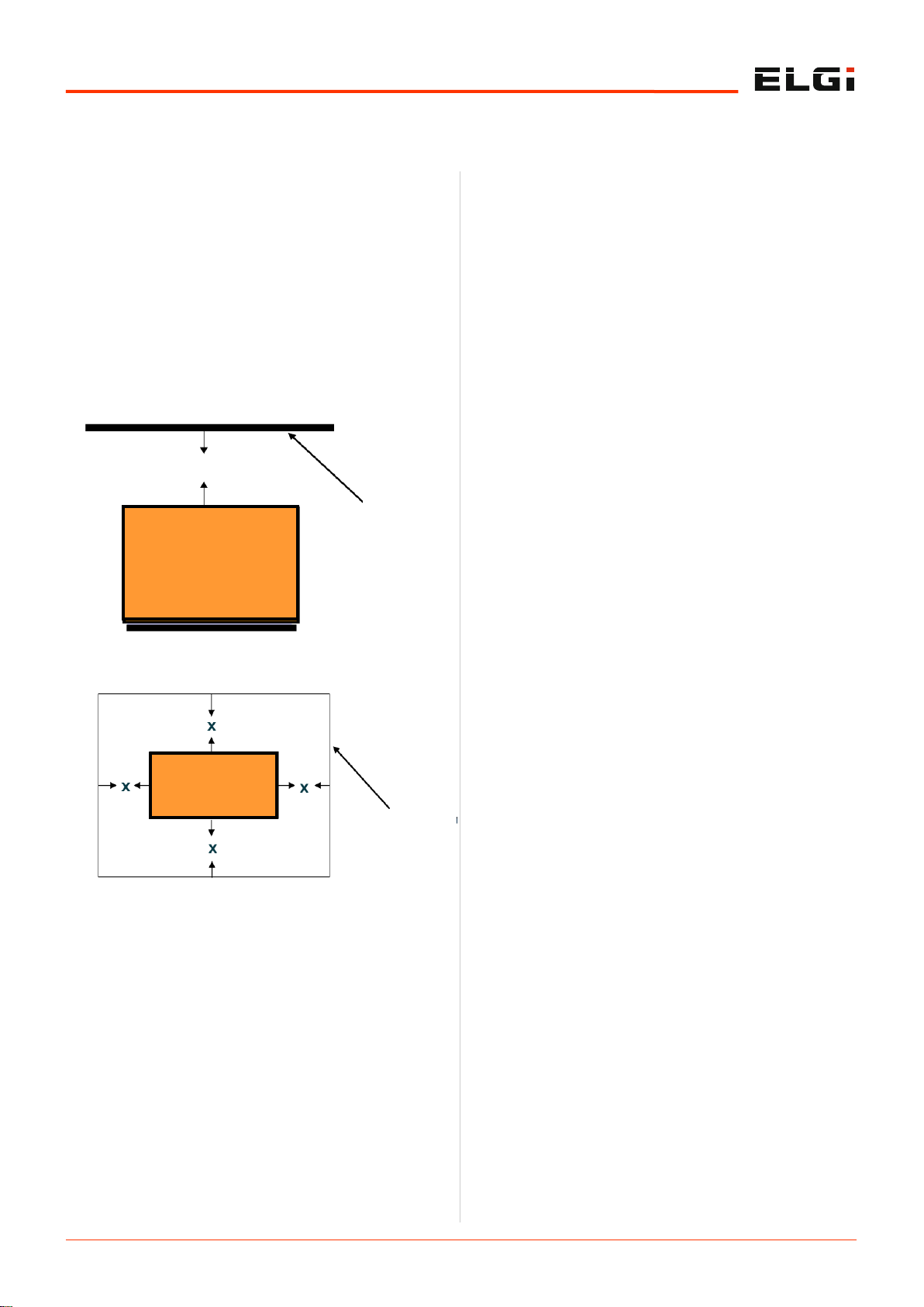
Leave a minimum of 1m (3.28ft) space around the
compressor for safe and proper inspection, cleaning,
and maintenance activities.
Leave a minimum of 2m (6.56ft) space above the
compressor for hot air to flow away from the
compressor.
Ensure the compressor is protected against direct
sunlight and rain.
Avoid exposing the compressor to excessive moisture
(from rain, dryer vent, etc.) as moisture can affect
airend lubrication, promote rust formation on the
compressor, and lead to electrical problems of the
motor.
Neither install the machine in a location where flame is
used nor place any inflammable objects near the
compressor.
Ensure the room temperature is within 45oC (113oF), as
high ambient temperatures will result in reduced oil life
due to higher discharge oil temperature (DOT). It also
results in high approach temperatures affecting the
cooling and condensation efficiency in the after-cooler
and in air treatment equipment like air dryers.
Ensure the hot medium of other utility equipment like
gensets/dryers/ boilers, etc., is not sucked by the
compressor inlet or that in any way the room
temperature does not rise to prevent high discharge oil
temperature.
Ensure the ambient temperature does not drop below
0oC (32oF). Provide air supply openings and adjustable
louvers to ensure that the minimum temperature does
not drop down below 0oC (32oF).
Install the compressor on a smooth, solid, level
industrial concrete floor capable of bearing the weight of
the compressor. Ensure unevenness of the surface is
within 6mm (0.25") and taper is within 50 per meter.
If the floor is splashed frequently with water while
cleaning, then place your compressor on a raised
concrete plinth 100 to 150 mm (4 to 6 inches) high.
Ensure the compressor base makes 100% contact
directly with the floor.
Know that an industrial floor with a level surface
capable of supporting the weight of the compressor is
sufficient for installing your compressor. No special
foundation or anchoring is necessary for rotary screw
compressors.
Do not store toxic, volatile, or corrosive agents near the
compressor.
Isolate the compressor from corrosive agents like
ammonia, chlorine, salt spray, and other chemicals as
these may erode the internal components and also
contaminate the oil and filters.
Do not allow hot air from additional equipment to blow
towards the compressor.
If you operate in high dust applications like rice mills,
cement, flour mills, etc., clean and replace the filters
more often.
Good practice is to have overhead lifting in the
compressor room to facilitate any major overhaul. If an
overhead hoist is not available, you should be able to
use a mobile crane or forklift truck in your compressor
room at a minimum.
5.1.5 Ventilation and exhausting hot air
Ensure adequate ventilation in the compressor
installation area. Your compressor has a ventilating air
requirement of 600 to 1200 cfm.
Figure 3. Vertical clearance around the
compressor
MINIMUM 2 m (6.6 ft) CLEARANCE
CEILING
ELGi SCREW AIR
COMPRESSOR
Figure 4. Horizontal clearance around the
compressor
ELGi SCREW AIR
COMPRESSOR
MINIMUM CLEARANCE, X=1 m (3.5 ft)
WALLS OR
OTHER
EQUIPMENTS
Page 26

5.4
Installation and operation
Guidelines to compressor ventilation setup:
Follow these guidelines when providing ventilation for the
compressor:
Provide openings close to the floor level on walls/
partitions close to the air suction side of the compressor
Provide exhaust openings close to the ceiling for hot air
exit.
Ensure the air velocity in the supply and exhaust ducts
does not exceed 13.1ft/s (4m/s).
Determine air velocity during commissioning using an
anemometer.
Do not connect cool air inlet ducts directly to the
compressor inlet side.
To eliminate transmission of vibrations, provide a soft
bellows connector between the duct and the
compressor.
Contact ELGi in case you need to provide a duct
connection or filter fitment on the compressor.
Do not direct forced flow of cool air towards the
compressor.
Locate the compressor such that hot air from other
machines is not directed towards it.
5.1.6 Electricals
Electricals 60Hz
You must provide a lockable main switch unit with preconnected slow-blow main fuses as per industrial safety
regulations. Power supply should be 208/230V 1 Ph 60Hz
with earth PE or 208-230V/460V 3 Ph 60Hz with earth PE.
The fuse and cable specifications for 208-230V, 60 Hz 1
Ph, 208-230V 60Hz 3ph and 460V 60Hz 3ph power
supplies appear in the table below.
You must also provide a switching fuse unit with preconnected slow-blow main fuses as per industrial safety
regulations. Power supply should be 208/30V 1 Ph with
earth PE or 208-230V/460V 3 Ph with earth PE.
The fuse and cable specifications for 208-230V, 60 Hz 3 Ph
and 460V 60Hz 3ph power supplies appear in the table
below.
Electricals 50Hz
You must provide a switching fuse unit with pre-connected
slow-blow main fuses as per industrial safety regulations.
The power supply should be 380V/400V/415V, 50Hz, 3
phase with (PE) earthing.
The fuse and cable specifications for 380V/400V/415V,
50Hz, 3 Ph power supplies appear in the table below.
You must provide a switching fuse unit with pre-connected
slow-blow main fuses as per industrial safety regulations.
The power supply should be 380V/400V/415V, 3 phase
with Neutral.
The fuse and cable specifications for 380V/400V or 415V,
50Hz, 3 Ph power supplies appear in the table below .
Ensure that only authorized electricians perform electrical
work. Study the electrical circuit diagram before starting
work.
NOTE
Suspended particulate matter should be less than 150 spm
to achieve the specified consumable life.
Guarantee is void if the compressor is operated above its
intended pressure.
Power supply
208-230
V 1Ph
208-230
V 3Ph
460 V
3Ph
380 V
3Ph
Motor Power kW/
hp
3.7/
5.5
5.5/
7.5
3.7/
5.5
5.5/
7.5
3.7/
5.5
5.5/
7.5
3.7/
5.5
5.5/
7.5
Nominal current
(A)
25 38 16 24 8 11 9 12.5
Cable material Copper conductor only
Power supply
cable (AWG)
(L=30ft)
3 x
10
3 x 8 4 x
12
4 x
10
4 x
14
4 x
14
4 x
2.5
4 x
4
Upstream fuses
(A) (Type RK/CC/
J)
32 50 20 32 16 16 16 16
Switching fuse
unit (A)
32 63 32 32 20 20 20 20
Power supply
208-
230 V
3Ph
208-
230 V
3Ph
460 V
3Ph
380 V 3 Ph
Motor Power kW/
hp
7.5/
10
11/
15
15/
20
7.5/
10
11/
15
15/
20
7.5/
10
11/
15
15/
20
Nominal current
(A)
32 47 63 15 23 29 17 24 34
Cable material Copper conductor only
Power supply
cable (AWG)
(L=30ft)
3 x 8 3 x 8 3 x 6 3 x
12
3 x
12
3 x
10
4 x 4 4 x 6 4 x
10
Upstream fuses
(A) (Type RK/CC/
J)
40 63 80 20 32 40 25 32 50
Switching fuse
unit (A)
63 63 100 32 32 63 32 32 63
Model
Recommended
pre-connected
fuse rating (A)
Incoming
copper cable
size (mm2)/
in
2
Incoming
aluminium
cable size
(mm2)/in2
2.2 kW 10 2.5/0.1 4/0.15
3 kW 10 2.5/0.1 4/0.15
4 kW 16 2.5/0.1 4/0.15
5.5 kW 16 2.5/0.1 4/0.15
5.5 kW 20 2.5/0.1 4/0.15
NOTE
Supply power to the compressor through a fuse switch unit
of a suitable rating mounted on the compressor at a height
of 5mm.
Page 27
5.5
Installation and operation
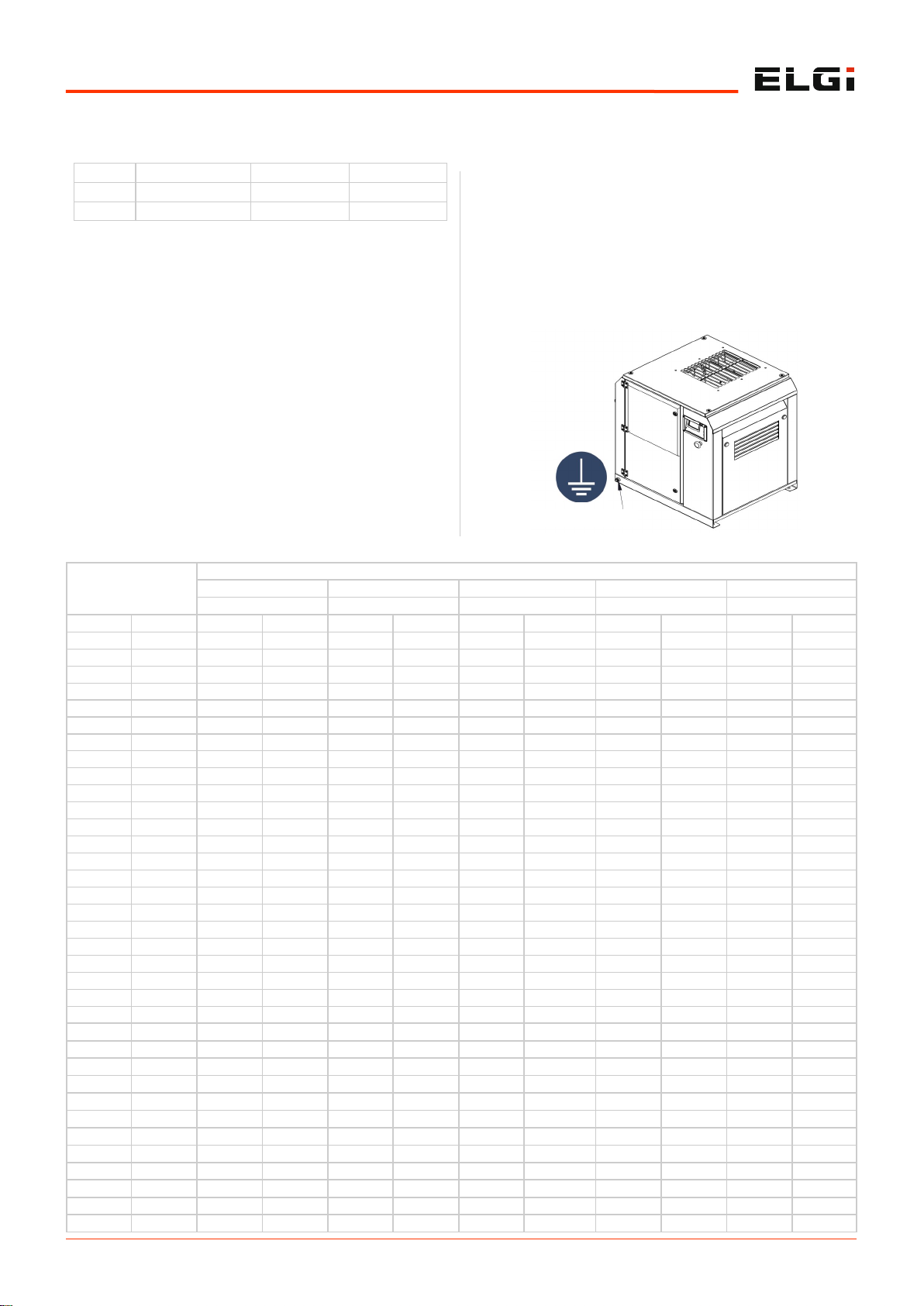
Earthing
Verify the total power supply requirements provided on the
compressor nameplate before connecting the compressor
to electrical lines. Connect the earthing line to the point
provided in the control panel box of the compressor.
Check the direction of rotation as per the arrow indication,
to check-start the compressor. Stop it immediately after
the check-start by pressing the emergency stop button.
Switch on the compressor after ensuring all the above
points and let it run at the rated speed.
In case of problems during the compressor operation,
check the warning fault code that appears in the controller
of the compressor. Refer to the Functional Description and
Operation sections of this manual to know more about the
fault.
If you hear any abnormal noise when operating the
compressor, switch it off immediately and contact the ELGi
service engineer.
Follow all above points when you need to reinstall the
compressor at a different location. If the compressor had
been in storage for an extended period before
commissioning, contact the ELGi service engineer.
Volume Flow FAD
NPS Pipe size/ Inside diameter (mm)
1/2 3/4 1 1 1/4 1 1/2
15.80 20.93 26.65 35.05 40.89
(m3/min) (cfm) (bar) (psi) (bar) (psi) (bar) (psi) (bar) (psi) (bar) (psi)
0.1 4 0.02 0.22
0.2 7 0.06 0.80 0.01 0.20
0.3 11 0.12 1.69 0.03 0.41 0.01 0.12
0.4 14 0.20 2.88 0.05 0.71 0.01 0.21
0.5 18 0.30 4.35 0.07 1.07 0.01 0.32 0.01 0.08
0.6 21 0.43 6.09 0.10 1.49 0.03 0.45 0.01 0.11
0.7 25 0.57 8.10 0.14 1.99 0.04 0.59 0.01 0.15
0.8 28 0.73 10.38 0.18 2.54 0.05 0.76 0.01 0.19 0.01 0.09
0.9 32 0.90 12.90 0.22 3.16 0.07 0.95 0.02 0.24 0.01 0.11
1 35 1.10 15.68 0.27 3.84 0.08 1.15 0.02 0.29 0.01 0.13
1.2 42 0.38 5.38 0.11 1.61 0.03 0.41 0.01 0.19
1.4 49 0.50 7.16 0.15 2.14 0.04 0.54 0.02 0.25
1.6 56 0.64 9.16 0.19 2.74 0.05 0.70 0.02 0.32
1.8 64 0.80 11.40 0.24 3.41 0.06 0.87 0.03 0.40
2 71 0.97 13.85 0.29 4.14 0.07 1.05 0.03 0.49
2.2 78 1.16 16.52 0.35 4.94 0.09 1.25 0.04 0.58
2.4 85 1.36 19.40 0.41 5.80 0.10 1.47 0.05 0.68
2.6 92 0.47 6.73 0.12 1.71 0.06 0.79
2.8 99 0.54 7.72 0.14 1.96 0.06 0.91
3 106 0.61 8.77 0.16 2.23 0.07 1.03
3.5 124 0.82 11.66 0.21 2.96 0.10 1.37
4 141 1.05 14.93 0.27 3.79 0.12 1.75
4.5 159 1.30 18.57 0.33 4.71 0.15 2.18
5 177 0.40 5.73 0.19 2.65
5.5 194 0.48 6.83 0.22 3.16
6 212 0.56 8.02 0.26 3.71
6.5 229 0.65 9.30 0.30 4.30
7 247 0.75 10.67 0.35 4.94
7.5 265 0.85 12.12 0.39 5.61
8 282 0.96 13.66 0.44 6.32
8.5 300 1.07 15.28 0.50 7.07
9 318 1.19 16.99 0.55 7.86
9.5 335 1.32 18.477 0.61 8.69
10 353 1.45 20.64 0.67 9.55
15 530 1.42 20.22
5.1.7 Air pipe dimensions
Figure 5. Earthing line of compressor
PAKAGE EARTHING
7.5 kW 25 4/0.15 6/0.25
11 kW 32 6/0.25 10/0.4
15 kW 50 10/0.4 16/0.6
Page 28

5.6
Installation and operation
Table 1. Global series – Air pipeline dimensions
Volume Flow FAD
NPS Pipe size/ Inside diameter (mm)
1 1/2 2 2 1/2 3 4
40.89 52.50 62.71 77.93 102.26
(m3/
min)
(cfm) (bar) (psi) (bar) (psi) (bar) (psi) (bar) (psi) (bar) (psi)
0.8 28 0.01 0.09
0.9 32 0.01 0.11
1 35 0.01 0.13
1.2 42 0.01 0.19
1.4 49 0.02 0.25 0.01 0.07
1.6 56 0.02 0.32 0.01 0.09
1.8 64 0.03 0.40 0.01 0.11
2 71 0.03 0.49 0.01 0.14
2.2 78 0.04 0.58 0.01 0.17
2.4 85 0.05 0.68 0.01 0.20 0.01 0.08
2.6 92 0.06 0.79 0.02 0.23 0.01 0.09
2.8 99 0.06 0.91 0.02 0.26 0.01 0.11
3 106 0.07 1.03 0.02 0.30 0.01 0.12
3.5 124 0.10 1.37 0.03 0.39 0.01 0.16
4 141 0.12 1.75 0.04 0.50 0.01 0.21
4.5 159 0.15 2.18 0.04 0.63 0.02 0.26 0.01 0.09
5 177 0.19 2.65 0.05 0.76 0.02 0.31 0.01 0.11
5.5 194 0.22 3.16 0.06 0.91 0.03 0.37 0.01 0.13
6 212 0.26 3.71 0.07 1.06 0.03 0.44 0.01 0.15
6.5 229 0.30 4.30 0.09 1.23 0.04 0.51 0.01 0.17
7 247 0.35 4.94 0.10 1.42 0.04 0.58 0.01 0.20
7.5 265 0.39 5.61 0.11 1.61 0.05 0.66 0.02 0.22
8 282 0.44 6.32 0.13 1.81 0.05 0.75 0.02 0.25
8.5 300 0.50 7.07 0.14 2.03 0.06 0.83 0.02 0.28 0.01 0.07
9 318 0.55 7.86 0.16 2.25 0.06 0.93 0.02 0.31 0.01 0.08
9.5 335 0.61 8.69 0.17 2.49 0.07 1.02 0.02 0.35 0.01 0.09
10 353 0.67 9.55 0.19 2.74 0.08 1.13 0.03 0.38 0.01 0.10
15 530 1.42 20.22 0.41 5.80 0.17 2.38 0.06 0.80 0.01 0.21
20 706 0.69 9.87 0.28 4.06 0.10 1.37 0.02 0.35
25 883 1.05 14.92 0.43 6.13 0.15 2.07 0.04 0.53
30 1059 1.46 20.90 0.60 8.59 0.20 2.90 0.05 0.75
35 1236 0.80 11.43 0.27 3.86 0.07 0.99
40 1412 1.03 14.63 0.35 4.94 0.09 1.27
45 1589 1.28 18.20 0.43 6.14 0.11 1.58
50 1765 0.52 7.46 0.13 1.92
55 1942 0.62 8.90 0.16 2.29
60 2118 0.73 10.46 0.19 2.69
65 2295 0.85 12.13 0.22 3.12
70 2471 0.97 13.91 0.25 3.57
75 2648 1.11 15.80 0.28 4.06
80 2824 1.25 17.81 0.32 4.58
85 3001 1.40 19.92 0.36 5.12
90 3177 0.40 5.69
95 3354 0.44 6.29
100 3530 0.48 6.92
150 5295 1.03 14.64
NOTE
The above table shows the pressure drops in 100m length
schedule 40 steel pipe at 7 bar (abs)
Page 29
5.7
Installation and operation
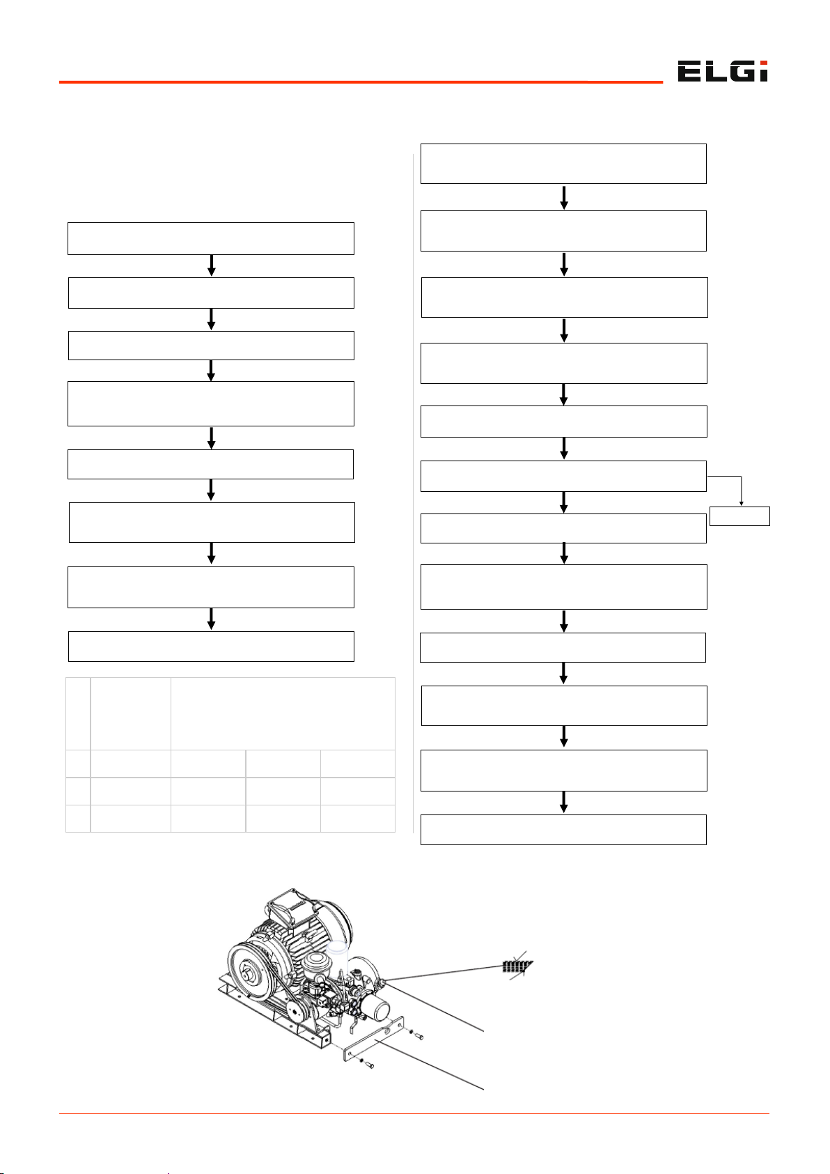
5.1.8 Oil fill procedure
Procedure for filling oil in a newly
assembled machine
5.1.9 Procedure for changing oil in the
compressor during service
Fill oil in the oil tank up to the over-fill cap
Close the oil filling plug
Run the compressor until the display tempera-
ture shows 158°F (70°C)
Stop the compressor
Refill oil in the tank to the max level indicated on
the tank and close the oil fill plug
Ensure sump pressure drops to atmosphere
pressure
Restart the compressor
Open the oil fill cap
Sl.
No.
Model
Volume of
oil
required
Initial fill
Second fill,
after
cranking
Litres
(gallons)
Litres
(gallons)
Litres
(gallons)
1 EN2 to EN5 1.6(0.4) 0.8(0.2) 0.8(0.2)
2 EN5x to EN11 6.2(1.6) 4(1.0) 2.2(0.6)
3 EN15 7.2(1.9) 4(1.0) 3.2(0.8)
MAXIMUM OIL LEVEL
OIL FILL PLUG WITH
BREATHER HOLE
JOINING PLATE
Dismantle the joining plate and drain oil from
the oil tank through the drain ball valve
Drain oil from the cooler through the drain plug
Drain oil from the airend by rotating the pulley
Shut off the compressor. Ensure sump pressure
drops to atmospheric pressure
Fill oil in the oil tank up to the over-fill cap
Close the oil filling plug
Run the compressor until the display tempera-
ture shows 158°F (70°C)
Stop the compressor
Refill oil in the tank to the max level indicated on
the tank and close the oil fill plug
Ensure sump pressure drops to atmosphere
pressure
Restart the compressor
Open the oil fill cap
Initial fill
Page 30
5.8
Installation and operation
5.1.10 Direction of rotation
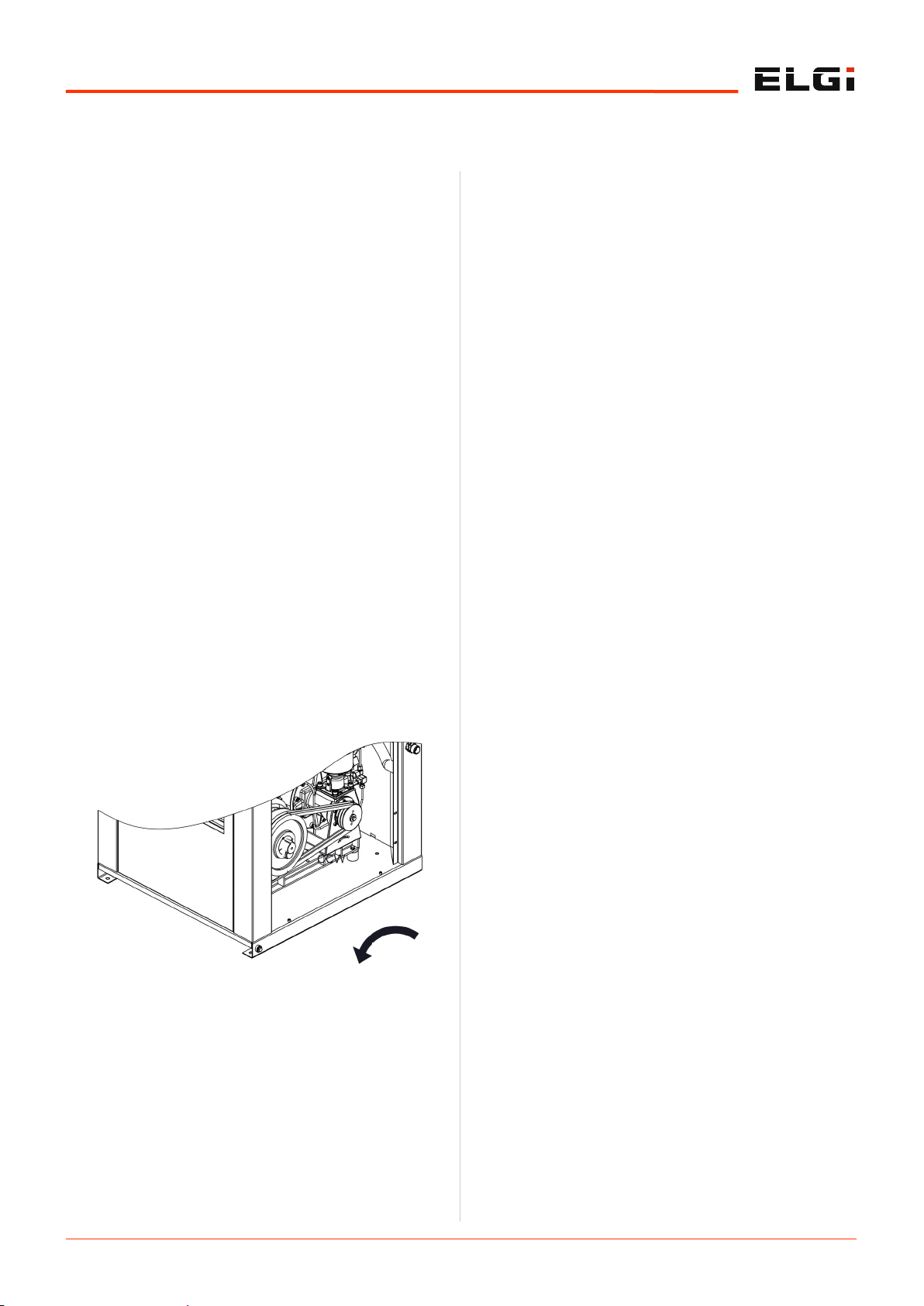
Check the direction of rotation of the main motor when
starting the compressor for the first time. You do this by
switching on the compressor and switching it off within 5
sec. Press the green start button to power on and the red
mushroom stop button to power down the compressor.
The motor must rotate in the clockwise direction when
viewed from the main motor cooling fan side. If the
direction of rotation is not correct, isolate the machine
from the electrical lines and interchange any two phases.
Restart the compressor and ensure that the direction of
rotation of the main motor is counterclockwise and the fan
motor is clockwise.
Switch on the compressor after ensuring all the above
points and let it run at the rated speed.
In case of problems during the compressor operation, note
the fault message in the controller display of the
compressor. Refer to the Functional Description and
Operation sections of this manual to know more about the
fault.
If you hear any abnormal noise when you run the
compressor, switch it off immediately and contact the ELGi
service engineer.
Follow all above points when you reinstall the compressor
at a different location.
If the compressor had been in storage for an extended
period before commissioning, contact the ELGi service
engineer.
ccw
Page 31

5.9
Installation and operation
If you do not intend to use the compressor for a prolonged
period, take special measures to ensure the protection of
the following components:
1. The airend
2. The motor
3. The air oil sump or receiver tank
5.2.1 Airend
Drain the oil from the air oil separator tank.
Rotate the airend drive pulley by hand as you remove
it.
Block the connection port completely.
Remove the intake filter and intake valve. Pour rust
preventive oil (Castrol DWX 32 or an equivalent grade/
brand) into the airend through the rotor intake area.
Rotate the drive pulley by hand so that rust preventive
oil spreads all over the bearings, seals, and other parts
of the airend.
Drain the rust-preventive oil by opening the drain plug
fully.
Refit the piping and belt.
Ensure that all the openings are plugged to avoid dust
entry.
This procedure protects the airend for up to six months
when the compressor is stored long. It must be
repeated every six months during prolonged storage.
5.2.2 Motor
Check the insulation of the motor winding.
Remove any moisture in the motor.
Check junction box terminals for tightness of wires.
Apply grease on motor bearings.
To prepare the motor for 1-year storage .
Other consumables
Oil filter element
Air filter element
Separator element
5.2.3 Air-oil separator tank
Drain the oil from the air-oil separator tank.
Remove the entire tank from the compressor after
disconnecting it from all hoses, the minimum pressure
valve outlet line, control pulse lines, and control
switches.
Clean the tank using DWX 32 oil.
The separator tank may now be stored for up to two
years. Replace the separator element before using the
compressor again.
5.2.4 Disposal of packing
The wood used in the shipping crates of the Encap series
compressor is biodegradable.
The polyethylene covers wrapped around the compressor
and the polystyrene packing provided around the electrical
panels are not recyclable. These must be disposed of in
accordance with prevailing environmental laws.
Preservation for long idle storage 5.2
Page 32

5.10
Installation and operation
5.3.1 Safety system and interlocking
device
5.3.1.1 Discharge temperature sensor
This sensor enables the dryer to shut down the
compressor if the discharge oil temperature mixture
reaches a preset value of 230°F (110°C) ± 41°F (5°C). It
resides on the airend outlet cover or the receiver tank.
5.3.1.2 Minimum pressure valve
This valve resides at the outlet of the oil separator and
maintains a minimum receiver tank pressure of about 58
psi. It facilitates proper air and oil separation, and oil
circulation to the airend.
5.3.1.3 Pressure relief valve
The pressure relief valve relives pressure in the oil
receiver tank when working pressure exceeds 217psi g
(15 bar).
5.3.1.4 Overload relays for main motor
and fan motor
These relays reside on the electrical control panel. They
ensure that the compressor shuts off when power
consumption exceeds a set value.
5.3.2 Operation control system
Perform these tasks before staring the compressor:
Fill oil in the tank as per the oil filling procedure.
Open all the doors and visually check the machine for
suitable operation.
Open the electrical panel at the front of the compressor
and check whether the three phases with earth PE are
connected securely.
Check the necessary grounding line in the band/
compressor base.
Ensure that you commission the machine only in closed
atmosphere air and on a level surface.
Provide a clearance space of 3ft (1m) around the
compressor.
The machine should be commissioned on a levelled
surface.
Use only the recommended input cable size and fuse for
the machine.
Connect the correct cable size to the machine wings.
For input power supply conditions, refer to 5.1.6.
5.3.3 Starting the equipment
Press the start button and check the direction of rotation
of the end pulley.
5.3.4 Starting and normal operation
mode
When you switch on the machine, the motor runs in DOL/
star delta mode. Within a few seconds, the inlet valve
opens and the compressor starts loading.
5.3.5 Unloading mode
After reaching the maximum cut-out pressure, the
pressure sensor estimates the pressure and cuts off the
solenoid electrical supply. At this stage, the blow down
valve unloads the separator tank and the compressor
starts to run in energy saving mode.
When the compressor runs continuously unloaded for 5
minutes in energy saving mode, it shifts to rest mode.
Unless the demand for air increases, the machine does not
restart. When air pressure falls, the compressor
automatically starts loading.
5.3.6 Stopping
Press the STOP button (red) on the controller to stop the
compressor.
5.3.7 Changing the compressor
settings
Change the compressor settings using the tactile keypad
and LCD panel on the controller. (Refer to the Neuron
manual for details on the control panel and interpretation
of the message.)
Operating instructions 5.3
Page 33

6.1
Maintenance
Chapter Page No.
6.1. Maintenance 6.2
6.1.1 Maintenance intervals 6.2
6.1.2 Daily operation 6.2
6.1.3 Air oil separator element (spin on type) 6.3
6.1.4 Oil filter (spin on type) 6.3
6.1.5 Oil cooler 6.3
6.1.6 Belt maintenance 6.3
6.1.7 Belt replacement 6.4
6.1.8 Belt and pulley data 6.4
6.1.9 Oil level check 6.6
6.1.10 Service procedure for minimum pressure valve 6.6
6.1.11 Service procedure for thermal valve 6.6
6.1.12 Condensate drain in tank 6.7
6.1.13 Procedure for draining the condensate 6.7
6.1.14 Anti vibration mount 6.7
6.2. Troubleshooting 6.8
6.3. Decommissioning, dismantling & putting out of service 6.13
6.3.1 Waste disposal 6.13
6.3.2 Dismantling the compressor 6.13
6.3.3 Decommissioning the compressor 6.13
6.3.4 Disposal of consumables and replaced parts 6.13
6.4. ELGi services 6.14
6.4.1 ELGi customer care system (ECCS) 6.14
6.4.2 ELGi genuine spare parts 6.14
6.4.3 Air audit 6.14
6.5. Appendix 6.16
6.5.1 Conversion tables 6.16
6.5.2 Torque values 6.17
6.5.3 Service log book 6.18
6.6. Disclaimers 6.20
Maintenance 6.0
Page 34
6.2
Maintenance
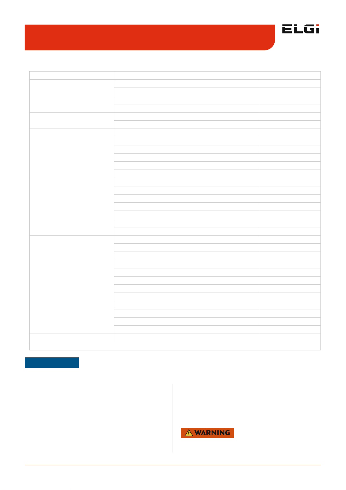
6.1.1 Maintenance intervals
6.1.2 Daily operation
Prior to starting the machine, check the oil level in the
separator tank. (See Starting the compressor in the
Operation section.) Should the level be low, add the
necessary amount. If you need to add oil too frequently, it
may indicate that a problem has developed which is
causing this excessive loss. Refer to the Troubleshooting
section (excessive coolant consumption) for a probable
cause and remedy.
After a routine start has been made, observe the machine
and monitor whether correct readings for that particular
phase of operation are being displayed. Good practice is to
perform a general check on the overall machine and
instruments after the machine has warmed up, to ensure
that the compressor is running properly.
Maintenance 6.1
NOTE
The above lifetime guidelines are applicable only to standard operating and regular maintenance conditions recommended in
this manual. In the event of changes in the conditions, consult ELGi.
Do not remove caps, plugs, or other components when the
compressor is running or pressurized. Stop the compressor
and relieve all internal pressure before doing so.
Frequency Part Remarks
Daily
Oil level Check
MOS condensate Check
Warning / alarms Check
Condensate in AOS tank Check
Weekly
Pre filter ( air intake, cooler, control panel) Clean
Air filter element Clean *
2000 hours or 6 months#
Oil & after coolers - air cooled (External) Check & Clean
Oil filter Replace
Oil Sampling **
Belt tensioning Check & Re-tension
Air filter element Replace
50 Hz motor - 2 pole grease Replace
4000 hours or every year
#
Pre filter ( air intake, cooler, control panel) Replace
Oil – Air lube XD / Air lube FG Replace
Air-oil separator element – Air lube XD / Air lube FG Replace
50 Hz motor ( 4 pole ) grease Replace
60 Hz motor (> 25HP ) grease Replace
Return line sight glass / orifice / NRV Check & Clean
Return line strainer Check & Clean
8000 hours or every 2 years
#
Air-oil separator element - UT Synthetic Replace
Oil - UT Synthetic Replace
60 Hz motor (≤ 25HP ) grease Replace
Electrical connections Check
Pipe coupling element Replace
Intake valve kit Replace
Thermal Valve Kit Check & Replace
MPV kit Replace
BDV kit Replace
Solenoid valve Replace
Safety valve Replace
Nylon tubes Replace
10000 hours Belt Replace
#- Whichever comes first * - As per air filer clog indicator ** - For USA region only
Table 2. Maintenance intervals
Page 35
6.3
Maintenance
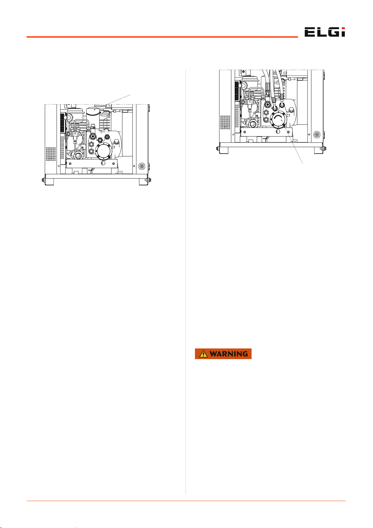
6.1.3 Air oil separator element (spin on
type)
To disassemble the existing air oil separator
Switch off and isolate the machine from the service line.
Vent air oil separator tank pressure and allow the tank
to cool for a few minutes.
Hold the air oil separator outer shell by the removed
strap belt and rotate it counterclockwise, until it
completely unscrews.
The hex adapter must be in the air oil separator head
during disassembly.
Check the recommended life of the air oil separator. If
the recommended life is over, replace it with a new air
oil separator.
Assembly of the new separator
Ensure the gasket of the separator is not damaged.
Clean the gasket-seating surface with a clean cloth.
Apply a thin film of oil on the mating surface of the
gasket.
Replace the separator and rotate it clockwise by hand.
Ensure no oil leaks from the mating surface. In case of
leaking, check the gasket.
After tightening by hand, rotate the separator further by
hand for one and a half rotations.
6.1.4 Oil filter (spin on type)
Disassembly of existing oil filter
Switch off and isolate the machine from the service line.
Vent air oil separator tank pressure and allow the tank
to cool for a few minutes.
Allow it to cool for a few minutes.
Hold the filter shell by the removed strap belt and
rotate it counterclockwise, until it completely unscrews.
Assembly of new oil filter
Ensure the gasket of the oil filter is not damaged.
Clean the seating surface with clean cotton.
Apply a thin film of oil on the mating surface of the
gasket.
Replace the oil filter and rotate it clockwise manually.
After tightening, rotate it further by hand for one and a
half rotations.
Ensure no oil leaks from the mating surface.
6.1.5 Oil cooler
External cleaning of oil cooler
Isolate the machine from the service line.
Vent separator tank pressure before performing
maintenance activities.
Use compressed air less than 36 psi g (2.5 bar) to clean
the outer surface of the cooler.
Replace the vent cover.
Internal cleaning of cooler
Use a 5 percent% (by volume) mixture of caustic soda
in water. Circulate this mixture at 140oF (60°C) in the
cooler for 5 hours. If required, increase the duration of
circulation.
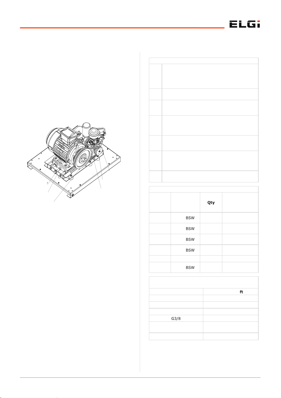
6.1.6 Belt maintenance
The belts must be tensioned regularly in order to avoid
compressor efficiency loss, belt slippage, and belt failures.
The belts are re-tensioned once every 2000 hrs.
To tension the belt:
Switch off and isolate the machine from the service line.
Isolate the machine from power supply.
Unlock and remove the belt guard, rear panel, and
motor side panel.
Do not tension belts when hot. Let them cool down to
<140°F (60°C) before performing belt maintenance.
Do not burn or dispose of the cotton lint in the cooler fins.
This may lead to deformation of the cooler.
It may also lead to expansion of the cooler joints, resulting
in leakage.
AIR OIL SEPERATOR
OIL FILTER
Page 36
6.4
Maintenance
Loosen the lock nut mounted in the belt tension bolt.
Screw the tension bolt clockwise.
Check the belt tension.
Tighten the lock nut.
Switch on the machine and verify running.
6.1.7 Belt replacement
To replace belts:
Switch off and isolate the machine from the service line.
Isolate the machine from power supply.
Unlock and remove the belt guard, rear panel, and
motor side panel.
Loosen the lock nut in the belt tension bolt.
Screw the belt tension bolt counterclockwise for five
revolutions.
Remove the old belts.
Remove and inspect the grooves for wear and tear.
Check the new belts to see if they are cracked or
damaged. If ok, place the new belts in pulleys without
damaging the belt.
Tighten the tensioning bolt.
Check the belt tension. Increase the tension if required.
Tighten the lock nut.
Switch on the machine and verify that the belt runs
without wobbling.
Let the machine run for 30 minutes.
Switch off the machine and allow the belts to cool
sufficiently.
Check the belt tension again.
Repeat the belt tensioning procedure to set the belts up
to the required static belt tension as specified in the
drive table .
6.1.8 Belt and pulley data
Procedure for assembling taper lock bush
Step
1
Clean and de-grease the bore and taper surfaces
of the bush and the tapered bore of the pulley.
Insert the bush in the pulley hub and line up the
holes. (Half thread holes must line up with half
straight holes.)
Step 2 Lightly oil the grub screws and screw them; do
not tighten yet.
Step
3
Clean and de-grease the shaft. Fit the pulley by
using the taper bush on the shaft and place it in
the desired position.
Step
4
When using a key, it should be first fitted in the
shaft keyhole. There should be a top clearance
between the key and the keyhole in the bore of
the bushing.
Step
5
Using the proper hexagon socket wrench,
gradually tighten the grub screws in accordance
with the torques as listed in the table below.
Step
6
When the drive has been operating under Step
load for a short period (half to one hour), check
and ensure that the screws remain at the
appropriate tightening torque.
Step 7 Fill the empty holes with grease in order to
remove dirt.
Torque values for taper lock bushes
Taper
lock
bush
number
Grub screw
used
Torque value
(lb. Ft)
1008
1108
1/4” 2 14.1
1310
1315
3/8” 2 14.8
1210
1215
3/8” 2 14.8
1610
1615
3/8” 2 14.8
2012 7/16” BSW 2 22.9
1610
1615
1/2” 2 35.5
Torque values for standard fasteners / fittings
Bolt size Torque lb
M6 7.8
M8 18.5
M12 64
52
G3/8 ( For Aluminium
interface)
44.2
HOSE Swivel nut 62.5
DRIVEN PULLEY
ANTI VIBRATION
MOUNT
V BELT
DRIVE PULLEY
LOCK NUT
TENSIONING
BOLT
Page 37

6.5
Maintenance
Drive table
DRIVE TABLE : EN2 - EN5 60HZ
Sl.
No
Belt & Pulley
parameters
UOM
2.2 125
2.2 150
3.0 125
3.0 150
4.0 100
4.0 125
4.0 150
4.0 175
5.5 100
5.5 125
5.5 150
5.5 175
1
Drive pulley
pitch circle
diameter
mm 95 90 170 125 150 140 150 140 200 224 200 132
2
Driven pulley
pitch circle
diameter
mm 100 100 140 100 80 85 100 100 80 100 90 67
3 Type of belt - XPZ
4
Pitch length of
belt
mm 812 812 987 812 850 850 875 875 950 1037 950 812
5
Static tension
of NEW BELT
N
94 -
100
97 -
104
153-
164
163-
175
159-
170
159-
171
156-
168
160 -
171
134 -
143
139 -
149
229-
246
137 -
147
6 No of belts Nos 2
7 Span length mm 252 256 249 228 239 245 238 247 240 248 241 245
8 Mass of belt g/m 60
DRIVE TABLE : EN2 - EN5 50HZ
Sl.
No
Belt & Pulley
parameters
UOM 2.2 -7
2.2 -
9.5
2.2-9.5
–1PH
3.0 -7
3.0 -
9.5
3.0 -
12.5
4.0 -7
4.0 -
9.5
4.0 -
12.5
5.5 -7
5.5 -
9.5
5.5 -
12.5
1
Drive pulley
pitch circle
diameter
mm 95 85 170 140 118 95 160 140 118 224 200 170
2
Driven pulley
pitch circle
diameter
mm 80 85 85 85 85 80 80 80 80 85 85 85
3 Type of belt - XPZ
4
Pitch length of
belt
mm 750 750 925 837 800 750 875 850 812 987 950 925
5
Static tension
of NEW BELT
N
167-
179
181-
193
181-
194
171-
184
191-
205
224-
240
121 -
130
123 -
132
131 -
141
151 -
162
160 -
171
153 -
164
6 No of belts 1 1 1 1 1 1 2 2 2 2 2 2
7 Span length mm 237 241 262 238 239 237 242 248 248 255 238 255
8 Mass of belt g/m 60
DRIVE TABLE : EN5X - EN15 50HZ
Sl.
No
Belt & Pulley
parameters
UOM
5.5X -7 5.5X -
9.5
5.5X -
12.5
7.5 -7
7.5 -
9.5
7.5 -
12.5
11-7
11 -
9.5
11 -
12.5
15-7
15 -
9.5
15 -
12.5
1
Drive pulley pitch
circle diameter
mm 190 125 132 200 170 180 200 180 190 190 190 180
2
Driven pulley pitch
circle diameter
mm 170 140 170 140 140 170 90 95 118 75 85 90
3 Type of belt - XPZ
4 Pitch length of belt mm 1212 1037 1112 1180 1112 1180 1112 1080 1140 1080 1080 1080
5
Static tension of
NEW BELT
N
147 -
158
147 -
158
148-
160
178 -
191
190-
203
192 -
206
242 -
259
248 -
265
240 -
257
318 –
340
319 –
341
331 -
355
6 No of belts 2 2 2 2 2 2 2 2 2 2 2 2
7 Span length mm 323 311 318 322 312 315 323 321 326 326 323 299
8 Mass of belt g/m 60
Page 38
6.6
Maintenance
6.1.9 Oil level check
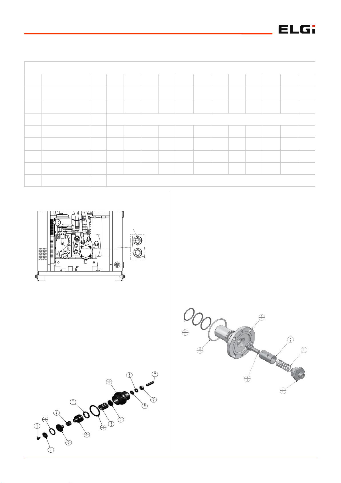
Conduct periodic checks on the oil level.
Top up oil if the oil level goes below the level shown
above.
6.1.10 Service procedure for minimum
pressure valve
Before disassembling the complete valve from the airend,
it is absolutely necessary to remove parts 12-15. Else, the
threaded part of body 1 will be damaged. Before removing
it, check the distance between the end of part 15 and the
top of part 1..
Remove the complete valve from the airend.
Remove and discard O-rings 9 and 11.
Remove screw 5 and part 4.
Replace O-ring 10 with a new O-ring from the repair kit.
Replace part 4 and screw 5.
Place the new O-rings 9 and 11.
Apply teflon grease on the interior of part 1.
Reassemble all components.
Reassemble parts 12-15. Return part 15 to the same
position.
6.1.11 Service procedure for thermal
valve
Disassemble the oil filter.
Disassemble the screw that fixes part 2.
Place and tighten the screws inside the removal tap of
part 2.
Remove the complete valve.
DRIVE TABLE : EN7 - EN15 60HZ
Sl.
No
Belt & Pulley
parameters
UOM 7-100 7-125 7-150 7-175
11-
100
11-
125
11-
150
11-
175
15100
15-
125
15150
15-
175
1
Drive pulley pitch
circle diameter
mm 140 170 150 132 150 160 150 150 160 160 170 150
2
Driven pulley pitch
circle diameter
mm 112 140 140 140 80 95 95 112 67 80 90 85
3 Type of belt - XPZ
4 Pitch length of belt mm 1037 1140 1080 1080 987 1037 1037 1037 987 1037 1037 987
5
Static tension of
NEW BELT
N
181 –
194
185 -
198
182-
198
183 –
197
245 -
263
238-
255
243-
260
240-
258
318-
338
309-
331
301-
323
317-
340
6 No of belts 2 2 2 2 2 2 2 2 2 2 2 2
7 Span length mm 320 326 312 326 310 316 324 312 308 327 311 332
8 Mass of belt g/m 60
MINIMUM OIL
LEVEL
Page 39
6.7
Maintenance
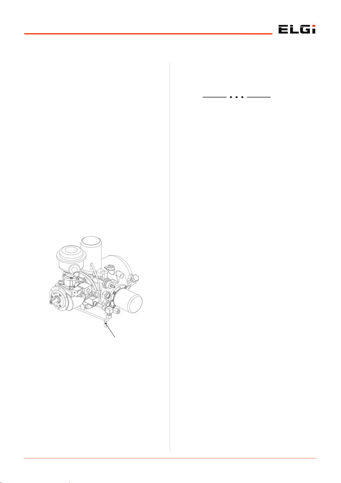
Remove and discard O-rings 5 and 6.
Remove nipple 7.
Remove parts 4 and 3.
Replace parts 3 and 4 with new parts from the service
kit.
Replace nipple 7.
Replace the new O-rings 5 and 6.
Apply teflon grease on O-rings 5 and 6.
Reassemble the complete valve.
6.1.12 Condensate drain in tank
If the duty cycle of the compressor (running hours) per
day is less than 16 hours, check for water condensation in
the air oil separator tank. When the compressor switches
off, the hot air inside the tank might condense when the
surrounding temperature lowers. In such cases, drain the
condensate from the separator tank weekly once or twice
depending on the moisture quantity. The condensate,
which is denser than oil, will settle at the lower part of the
tank.
6.1.13 Procedure for draining the
condensate
To drain the condensate in the tank:
Switch off and isolate the machine from the service line.
Unscrew the drain plug from the oil drain line.
Slightly open the drain ball valve.
Check for water in the valve outlet. Close the valve
immediately after draining the water to prevent leakage
of more oil.
Replace the drain plug. Tighten it firmly to avoid leaks.
Dispose of the drained condensate as per the local
environmental procedure.
6.1.14 Anti Vibration Mount
Anti Vibration Mount should be replaced during major
overhaul of airend or motor. If no such situation, replace
AVM every 5 years
DRAIN BALL VALVE
Page 40

6.8
Maintenance
Troubleshooting 6.2
This guide includes the most likely problems with possible causes. In case of a problem, follow the diagnosis in sequential
order as mentioned in the following charts. Before performing any work in this unit, be sure to cut off electrical supply,
depressurize the entire compressor, and isolate the unit.
Problem Cause Solution (go sequentially)
Compressor not
starting
Power supply not available Restore incoming power supply.
Incoming voltage is below limit
(1) Correct the incoming voltage.
(2) Ensure the isolator is within 5m from the compressor.
(3) Ensure sufficient power backup.
(4) Select and use the correct cable size.
Emergency stop switch in pushed
condition
Rotate counterclockwise and release.
Emergency stop switch malfunction
Clean or replace the emergency switch.
Tighten the wires at terminals.
Isolator fuse blown
(1) Select the correct fuse rating from the selection chart.
(2) Check and correct the short circuit within the control
panel.
(3) Dedicated isolator to be provided to the compressor.
(4) Check and correct the motor winding/body short after the
megger test.
Incoming phase-to-phase voltage
imbalance of more than 5V
Correct incoming voltage.
Adjust main incoming transformer tapping.
Correct the power factor to less than unity.
Incoming phase-to-earth voltage
imbalance of more than 5V
Correct incoming voltage.
Control MCB malfunction Replace MCB
Control fuses inside compressor
control panel blown
Check for any short circuit or loose connection.
Replace the solenoid valve/control transformer if defective.
Replace the glass fuse (2A for Neuron, 1A for the control
circuit).
Control transformer fuse blown
Replace the control transformer if defective.
Replace the glass fuse (0.25A for Neuron, 0.5A for the control
circuit).
No power supply to Neuron
controller.
(1) Replace control transformer fuses.
(2) Ensure tight connection of the 24V power supply connector
to Neuron.
(3) Replace the control transformer (50VA).
No display in Neuron controller
(1) Replace the control transformer (50VA).
(2) Replace the control fuse.
(3) If 24V power supply to Neuron is okay, then replace with a
new Neuron micro controller.
Page 41

6.9
Maintenance
Problem Cause Solution (go sequentially)
High discharge oil
temperature
Oil level is low
(1) Check and refill oil to correct the level (in stopped
condition).
(2) Refer to the diagnosis procedure for high oil carry-over.
(3) Arrest oil leaks.
(4) Ensure the correct grade of oil is used.
Room temperature is higher than
outside ambient temperature by
30°C (86°F)
Improve ventilation in the compressor room.
Oil cooler clogged externally
Clean the cooler assembly/pre-filter mesh (if available)
externally by first using a fibre brush and then by blowing
compressed air at 87 psi g (6 bar).
For sticky dust, remove the cooler, close all the cooler ports
with dummy plugs, and do a water-wash with soap oil.
Install the cooler pre-filter mesh.
Cooling fan rotating in wrong
direction.
Check and correct the wiring connection to the cooling fan.
Replace with the correct fan type.
Check fan motor fuse
Replace the fuse if blown.
Replace with the 2A fuse.
Cooling fan not working. Check and ensure the neutral connection is complete.
Temperature sensor malfunction
Replace the sensor.
Tighten/recrimp the connection with the adaptor.
Oil filter clogged
Replace the oil filter.
If required, replace the oil (based on the condition of oil) and
run the compressor.
Thermal valve malfunctioning Replace the thermal valve element.
Oil injection orifice chocked or
improper size
Clean the oil injection orifice.
Replace with correct size.
Air filter clogged Clean or replace the air filter.
Air–oil Separator element clogged
Verify pressure drop is less than 14.5 psi g ( 1bar).
Replace oil.
Replace separator element.
Poor quality of oil Replace oil.
Oil cooler clogged internally
Check for pressure drop across the oil cooler if less than 21 psi
g (1.5 bar).
Check and clean the cooler internally with 20L of isopropyl
alcohol + toluene mixture in the 1:1 ratio and circulate for 4
hours with external 1 HP pump.
Refit the cleaned cooler and, if required, replace oil (based on
the condition of oil) and run the compressor.
Page 42

6.10
Maintenance
Problem Cause Solution (go sequentially)
High oil carry-over
High oil level
Drain excess oil and maintain the recommended oil
level.
Oil is milky Replace oil and maintain the recommended level.
Scavenge return line tube clogged
Remove and clean the clogged scavenge return line
tube.
Replace the internal pipe.
High discharge oil temperature (DOT) Refer to the diagnosis procedure for high DOT.
Improper grade of oil Use ELGi recommended air lube oil.
Separator punctured/collapsed Replace with a new separator.
Separator element bonding ruptured Replace with a new separator.
Compressor runs at lower pressure than
normal.
1) Use a suitable higher capacity compressor or match
demand to compressor capacity.
Compressor runs at lower pressure than
normal.
2) Arrest all line leakages.
Minimum pressure valve (MPV) opens
earlier than the specified opening pressure
of 65 psi g (4.5 bar).
Replace MPV kit/assembly.
Neuron microcontroller pressure settings:
1) Unload pressure set value is above
specification.
2) High tank pressure set value is below
Check and correct unload pressure and high tank
pressure values in the Neuron micro-controller.
1) Check and replace the intake valve kit if required.
Intake valve malfunction
2) Check the solenoid valve and clean or replace if
required.
High tank pressure
Intake valve malfunction 3) Check and replace the actuator kit if required.
BDV malfunction
Check/replace.
Open the outlet ball valve.
Check the solenoid valve and clean or replace if
required.
Neuron microcontroller malfunction Replace the Neuron microcontroller.
Pressure transmitter malfunction Replace the pressure transmitter.
MPV stuck up (check with pressure gauge in
AOS tank )
Replace the MPV kit.
Separator element choked Replace the separator element.
Pressure transmitter malfunction Replace pressure transmitter
MPV stuck up (check with pressure gauge in
AOS tank )
Replace MPV kit.
Separator element choked
Replace separator element
Page 43

6.11
Maintenance
Problem Cause Solution (go sequentially)
No control air supply to solenoid valve Replace/connect
Loading/unloading
problem
Solenoid valve malfunctioning
1. Replace the solenoid valve assembly.
2. Clean the orifice.
No electrical supply for energizing the
solenoid valve
Replace the Neuron microcontroller.
Intake valve malfunctioning Check and replace the intake valve kit.
Blow-down valve malfunctioning
1. Clean or change the BDV assembly.
2. Clean the orifice.
MPV malfunctioning
1. Check and change the MPV kit.
2. Check and change the MPV assembly.
1. Air requirement is more than compressor
capacity
1. Replace the compressor.
2. Arrest all pipeline leakages.
1. Replace the compressor.
3. Excess pressure drop in pipeline
1. Replace the compressor.
2. Arrest all pipeline leakages.
Pressure transmitter malfunction
1. Tighten the lap cable.
Pressure transmitter malfunction
Pressure transmitter malfunction
Pressure transmitter malfunction
4. Replace the Neuron microcontroller.
Replace the Neuron microcontroller.
Disable 'unload mode' in the operator settings of the
Neuron microcontroller.
4. Replace the Neuron microcontroller
Malfunction of R04 relay (loading/ unloading
relay) in Neuron microcontroller
Replace Neuron microcontroller
Unload mode enabled in Neuron
microcontroller
Disable 'unload mode' in operator settings of Neuron
microcontroller
Page 44

6.12
Maintenance
Problem Cause Solution (go sequentially)
Inlet air pre-filter mat clogged
Clean/change the pre-filter mat by following these
steps:
Switch off the machine.
Squeeze and pull out the pre-filter mat from the
canopy.
Clean the pre-filter with compressed air at less than
7 bar g.
Refit the filter after cleaning.
Pressure not built
up
Clogged air filter element
Clean/change air filter element
1. Air requirement is more than compressor
capacity
1. Replace the compressor.
2. Arrest all pipeline leakages.
2. Working pressure is lower than required
application pressure
3. Excess pressure drop in pipeline
No control air supply to solenoid valve Replace / connect the control line tubes.
Solenoid valve malfunctioning
1. Replace the solenoid valve assembly.
2. Clean the orifice.
No electrical control supply to solenoid valve Replace the microcontroller.
Intake valve malfunctioning Check and replace the intake valve kit.
Blow-down valve malfunctioning
1. Check and change the BDV assembly.
2. Clean the orifice.
MPV malfunctioning
1. Check and change the MPV kit.
2. Check and change the MPV assembly.
Separator element choked (increase in
pressure drop across separator)
Replace the separator element. If required, replace
oil (based on the condition of oil) and run the
compressor.
2. Change pressure regulator assembly.
Actuator failure (applicable only to EG 55 to
EG 250)
Check and change actuator / kit / assy.
Separator element choked (increase in
pressure drop across separator)
Replace separator element. If required replace the
oil (based on condition of the oil) and run the
compressor.
Page 45

6.13
Maintenance
If you do not intend to use the compressor or any of its
parts, you must dismantle and put it out of service. These
tasks must be performed in compliance with the standards
in force of that particular country.
6.3.1 Waste disposal
Use of the compressor generates waste. The residues
from agricultural, industrial, crafts, commercial, and
service activities must be treated as waste, which needs
to be disposed of properly. Deteriorated or obsolete
machines are also classified as waste.
Special attention must be given to active carbon filters
as they cannot be included in urban waste. Observe the
waste disposal laws in force where the compressor is
used.
It is mandatory to record loading or unloading of
exhausted oils, obsolete machines, and toxic harmful
wastes that derive from heavy or light industry
processes.
It is especially important that exhausted oils be
disposed of in compliance with the laws in the countries
of use.
6.3.2 Dismantling the compressor
Dismantle the compressor in accordance with all the
precautions imposed by the laws in force in the country
of use.
Before dismantling, request an inspection by the
relevant authorities. Disconnect the compressor from
the electrical system.
Eliminate any interfaces the compressor may have with
other machines, making sure that interfaces between
remaining machines are unaffected.
Empty the air oil tank containing the lubricating oil and
store in compliance with the laws in force.
Proceed with the disassembly of the individual
compressor components and group them together
according to the materials they are made of: Steel,
Stainless Steel, Aluminum and plastic parts.
Then scrap the machine in compliance with the laws in
force of the country of use.
6.3.3 Decommissioning the compressor
Remove the foundation for the compressor.
Unplug the power cable entry to the compressor.
Drain the oil from the cooler and air oil tank. Dispose of
it properly.
Make sure all the compressed air is vented out through
ball valves and safety devices residing in the
compressor.
Ensure that all the external supply lines have been
properly disconnected from the compressor before
decommissioning.
6.3.4 Disposal of consumables and
replaced parts
The moisture condensate separated from the
compressed air contains oil particles. Disposal of
condensate and the filter element is to be performed in
accordance with the pollution control norms prevailing
at the time of compressor installation or use.
Parts of the compressor that are replaced have metal
and rubber components. These may be recycled and
disposed of according to pollution control regulations,
respectively.
Rubber items such as AVMs, coupling elements, and O-
rings should be disposed of and replaced before running
again.
Decommissioning, dismantling and
putting out of service
6.3
The compressor does not give any warnings during short
operating times. If it is operated below the dew point and
moisture, then condensate may mix with oil. This will
reduce the lubricating quality of the oil and lead to damage
of the compressor.
ELGi is not responsible for the disposal of old oil or
condensate. It is the responsibility of the customer to
dispose of the foregoing in accordance with local
environmental statutory laws.
NOTE
Page 46

6.14
Maintenance
6.4.1 ELGi customer care system (ELGi
CCS)
ELGi provides dedicated customer care and after-sales
support through the ELGi customer care system (CCS), a
computerized system developed in-house. The CCS aims
to minimize the time taken to resolve customer
complaints.
Service requests/complaints
The CCS toll-free telephone number 1800-425-3544
(accessible within India through BSNL and MTNL lines)
takes the customer’s call to our centralized customer care
center in Coimbatore. Customers can register their service
requirements or complaints here.
A unique tracking number is generated for each call logged
by the CCS. The customer receives an automatic e-mail
acknowledgement with the tracking number and details of
the call for reference.
A service engineer is assigned to the call, and the date and
time of the engineer’s visit are communicated to the
customer by e-mail. Every requirement or complaint must
be resolved and closed in the CCS within a specified time
limit, failing which the complaint is automatically brought
to the notice of the manager. If the issue remains
unresolved, it will get escalated to the managing director.
The CCS ensures that not only the customer complaints
are logged but they are also attended to on time, every
time.
Enquires
A number of calls received by the CCS relate to customer
queries regarding products and spare parts. The details
are noted, and basic information on product specifications
and usage are provided. The caller is then referred to a
salesperson at the head office or the appropriate branch
for follow-up.
The CCS database
The CCS also creates a database of customers, adding
details of every new customer who calls, thereby building
a large pool of installation details. These details are used
to provide value-added services to improve customer
satisfaction with ELGi products.
CCS-working hours
The ELGi CCS works for six days a week from 08:30 to
21:30 IST (Monday to Saturday).
Multi-lingual capability
The coordinators at the CCS are multi-lingual. They can
handle calls in English and all the major regional
languages of India.
Coverage: The CCS toll-free number 1800-425-3544 is
accessible from the following areas:
Southern Region: Tamil Nadu, Karnataka, Kerala,
Puducherry, Andhra Pradesh, Telangana, Andaman &
Nicobar Islands.
Western Region: Maharashtra, Gujarat, Madhya
Pradesh, Goa, Lakshadweep Islands.
Eastern Region: Orissa, Chhattisgarh, Jharkhand,
West Bengal, Bihar and the North-Eastern states.
Northern Region: Rajasthan, Uttar Pradesh, Delhi,
Haryana, Punjab, Uttaranchal, Himachal and Jammu &
Kashmir.
Contact Numbers: You can contact CCS also with the
following numbers:
Telephone: 0422-2589206 / 241 / 242 / 243/ 244 / 245 /
97900 21100
Fax: 0422-2589240
Please send the following details to the mail, thus enable
us to take immediate action.
1. Name of the customer
2. Compressor model
3. Fab. number
4. Contact person name
5. Phone number
6. Nature of complaint
7. Hour meter reading
You may use the CCS by sending e-mail to: [email protected]
Customer satisfaction survey
If you have used the CCS, you may be contacted for your
feedback on our after-sales support. Your response helps
ELGi to improve its service.
International customers:
Refer contact information at the end of this manual book.
6.4.2 ELGi genuine spare parts
When ordering spare parts, refer to the lists provided in
the parts manual and identify the part number. Specify the
part number and quantity, in addition to the name plate
details. Global support center of ELGi ensures the supply
of the quality spares on time. Ensure that you are using
the genuine spare parts so that your Compressor will be
working efficiently and effectively. Refer to section 6.1.3
for details on need of using genuine spares.
Please contact our After sales team for any compressor
accessory requirements like VFD, Air-Dryer, etc.
6.4.3 Air audit
We extend our proven capabilities in energy efficiency
initiatives by carrying out air audits for our customers.
ELGi conducts audits and trains end users in key energy
oriented functional areas. The audit reports prepared by
ELGi experts’ team include recommendations on short,
ELGi Services 6.4
Page 47

6.15
Maintenance
medium and long term measures for energy conservation,
along with financial estimates and analysis for
implementation.
This air audit objective is to provide the customer:
The framework for systematic collection of data relevant
to the efficient operation of compressed air systems.
A thorough analysis about the performance of the
compressed air system, identifying potential electricity
savings and to provide sound recommendations for
implementation of energy efficiency initiatives.
Data analysis will be comprised of the information about
different areas such as air leakages, inappropriate use of
compressed air, compressed air system network,
compressed air system supply including compressor
internal maintenance conditions and even more.
The final report issued to the customer end will serve
the purpose of assisting concise, consistent and complete
presentation of the analysis, findings and recommendations
arising from a compressed air system audit.
Depending on the measurement, reporting and cost
requirements from the customer end, the intensity in level
of audit (base level or investment level) will be decided.
Also post implementation monitoring after air audit will be
provided if requested from the customer end.
For further information on air audit contact ELGi.
E-Mail: [email protected]
Page 48

6.16
Maintenance
Description From To Multiply by
Length (L)
Inches Millimetres 25.4
Metres Inches 39.37
Feet Millimetres 304.8
Metres Feet 3.281
Inches Thou 1000
Millimetres Micrometres 1000
Area (A)
Square metres Square feet 10.765
Square feet Square inches 144
Square inches Square millimetres 645.16
Volume (V)
Cubic metres Cubic feet 35.315
Cubic feet Cubic inches 1728
Cubic metres Litres 1000
Cubic feet Litres 28.32
US gallons (liq) Litres 3.785
Imperial gallons (liq) Litres 4.546
Volumetric flow (Q)
Cubic feet per minute (cfm) Cubic metres per hour (m3/h) 1.6988
Cubic feet per minute (cfm) lpm 28.32
Cubic metres per hour (m3/h) lpm 16.667
Cubic metres per minute (m3/min) lps 16.667
Mass (M)
Kilograms Pounds 2.205
Kilograms Grams 1000
Kilograms Ounces 35.27
Pressure (P)
kg f/cm2 g psi g 14.223
psi g Pascal 6895
bar g kg f/cm2 g 1.0197
bar g psi g 14.503
psi g kg f/cm2 g 0.0703
Temperature (T)
Degree Celsius (°C) Degree Fahrenheit (°F) °F = 9(°C)/5 +32
Degree Celsius (°C) Kelvin (K) K = °C + 273.15
Degree Fahrenheit (°F) Degree Rankine (°R) °R = °F + 460
Heat (q), Work (W),
Energy (E)
ft-lb f Joules 1.35582
ft-lb f Btu 0.001285
Joules Calories 0.2388
Btu/h Calories/h 252
Kilowatts Btu/h 3411
Metric horsepower Kilowatts 0.7355
Power (P)
Imperial horsepower Kilowatts 0.7457
6.5.1 Conversion tables
Appendix 6.5
Table 3: Conversion table
Page 49

6.17
Maintenance
6.5.2 Torque values
The tightening torque values for bolts and screws used in ELGi Compressors are provided in this section for reference. The
tolerance for the torque values is (-) 10% from the given value.
* Property class of 8.8 only
Thread size (inches) Tightening torque (N-m) Tightening torque (lb-ft)
9/16" 149 109.8875
7/8" 579 427.0125
Table 6: UNF threads
Thread size (inches) Tightening torque (N-m) Tightening torque (lb-ft)
¼" 45 33.19
½" 85 62.69
¾" 170 125.38
1" 330 243.39
1¼" 430 317.15
1½" 510 376.15
Table 5: BSP threads
Thread size* Tightening torque (N-m) Tightening torque (lb-ft)
M4 2.9 2.13
M5 5.7 4.20
M6 9.8 7.22
M8 24 17.7
M10 47 34.66
M12 81 59.73
M16 197 145.28
M20 385 283.93
Table 4: Metric hexagonal head bolts and screws
Page 50

6.18
Maintenance
6.5.3 Service log book – record of maintenance
Date From
Till
Total
operated
hours /
day
Line
pressure
System
pressure
Discharge
temperature
Oil level
in AOS
tank
Moisture
removal
from AOS
tank
Pre
Filter
Cleaning
Cooler
cleaning
Trip
record
descrip-
tion
Comments
Operator
sign
Low/
normal/
high/
change
Before
starting
Start/Stop
Time
Page 51

6.19
Maintenance
Date From
Till
Total
operated
hours /
day
Line
pressure
System
pressure
Discharge
temperature
Oil level
in AOS
tank
Moisture
removal
from AOS
tank
Pre
Filter
Cleaning
Cooler
cleaning
Trip
record
descrip-
tion
Comments
Operator
sign
Low/
normal/
high/
change
Before
starting
Start/Stop
Time
Page 52

6.20
Maintenance
Please read this document and the warranty terms accompanying the product carefully before using our product.
By purchasing our product, you agree that you will assume total responsibility and risk for your use of the product.
The warranty terms of the product have been provided separately.
1. ELGi is not liable for failure of the compressor ( hereinafter “compressor” or “product”) to perform its obligations if such
failure is as a result of Acts of God (including but not limited to fire, flood, earthquake, storm, hurricane or other natural
disaster), war, invasion, act of foreign enemies, hostilities (regardless of whether war is declared), civil war, rebellion,
revolution, insurrection, military or usurped power or confiscation, terrorist activities, nationalization, government
sanction, blockage, embargo, labour dispute, strike, lockout or interruption or failure of electricity or telephone service
and any other reasons beyond ELGi’s control.
2. ELGi does not take responsibility for any damage or injury resulting from neglecting the safety instructions, warnings,
cautions, precautions, or non-observance of the normal caution and care required for installation, operation, maintenance
and repair of the product, even if not expressly stated, and such instances are specifically disclaimed by ELGi.
3. The entire literature including product description or any other information in this manual exclusively belongs to ELGi and
is subject to copyright. No person has any right to copy, modify, distribute, transmit, display, perform, reproduce, publish,
license, create derivative works, transfer or sell any information, or deal with the same in any other manner, without the
knowledge and written concurrence of ELGi, violation of which would amount to infringement of rights of ELGi and would
necessitate legal action.
4. The information published in this manual may include inaccuracies, or typographical errors. Changes may be periodically
added to the information herein. Any changes/improvements may also be made to the products stated in this manual and
ELGi is not liable if the readers are not updated with information.
5. Likewise ELGi is responsible only till the point of first sale to the ultimate customer and not thereafter and only if the
product is purchased from authorized dealers of ELGi. ELGi disowns liability on account of purchase of any second hand
product or purchase otherwise from unauthorized dealers. ELGi shall not be liable for any indirect, incidental, punitive,
special or consequential losses or damages including any loss of profit, loss of production, loss of income or contract, loss
of goodwill, expected savings or business relationships, arising out of or in any way connected with the usage of the
product or information in this manual.
6. In no event ELGi shall be liable for any claims or loss having a value higher than the original purchase price of the product
sold by ELGi or its network of authorised dealers.
7. These Disclaimers and the contents of this manual shall be subject to the laws of India and any disputes pertaining to this
manual or anything stated therein or any product stated therein is subject to the exclusive jurisdiction of the courts in
Coimbatore, Tamil Nadu, India.
8. No liability in connection with the product will accrue to ELGi,
If any welding or related operation involving heat is carried out in the compressor. Never weld or modify any parts
including pressure vessels.
If any damages to the product directly or indirectly arise due to long storage (6 months) of product and subsequent
corrosion of internal parts and which leads to fire or malfunctioning of the product.
If the compressor package and its accessories are installed in such a way to allow moisture, rain, freezing temperature or
sun damage to affect the safe operation of the unit.
If the person who operates / maintains the compressor does not adhere to all work related safety practices and regulatory
requirements.
If unauthorized personnel other than ELGi authorized or trained personnel carries out commissioning, installation,
operation, maintenance and any repair work on the compressor.
If the compressor and the compressed air are used for unintended use or are misused.
If the compressor is operated below or in excess of its pressure and temperature limits.
If the compressor “ON/ OFF” switch is operated through remote control situated away from the compressor location
without giving any adequate notice / alarm before starting the product .
© Copyright ELGi Equipments Limited, India 2018. All Rights Reserved.
Disclaimers 6.6
Page 53
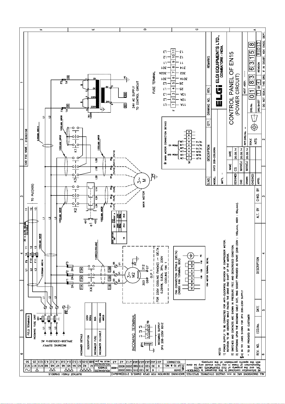
Page 54
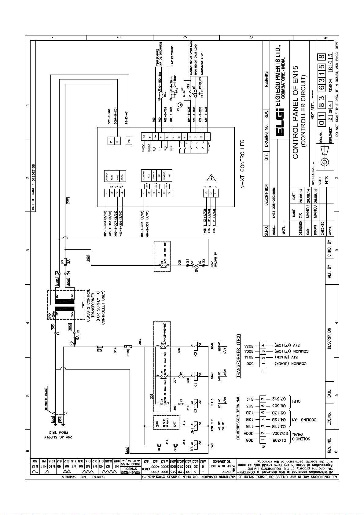
SUPPLY : 24V AC
X01
X02
X03
X04
X05
Page 55
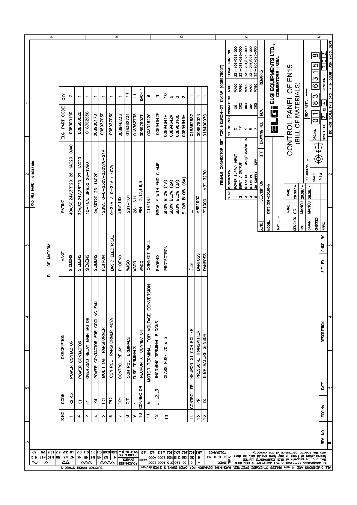
Page 56
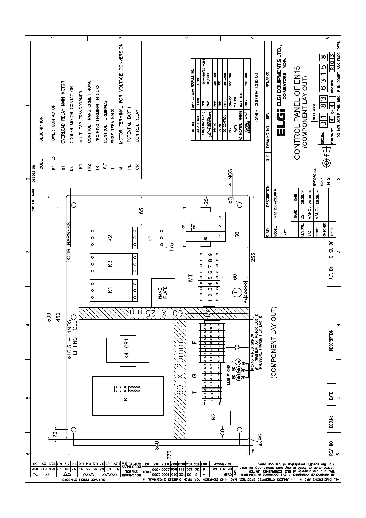
Page 57

 Loading...