

ELGi EG Series, EG 22, EG 11 Operation And Maintenance Manual

EG SERIES ELECTRIC POWERED
SCREW AIR COMPRESSOR
EG 11 to EG 22
(15 HP to 30 HP)
Standard and Standard + VFD
208 - 230V / 460V, 3Ph, 60Hz
OPERATION AND MAINTENANCE MANUAL

Part / Document No. 019400022 Rev R08
Print Status
April 2017

List of Contents
OPERATION AND MAINTENANCE MANUAL
Introduction 5
Salient Features 7
Safety 8
Operating Precautions 8
Technical Specifications 10
Commissioning Process 11
Installation 11
Disposal Of Packing 20
Functional Description 21
Maintenance 27
Maintenance Schedule 41
Decommissioning Dismantling And Putting Out Of Service 42
Disposal Of Consumables And Replaced Parts 42
Troubleshooting 43
Conversion Tables 47
Torque Values 48
Service Log Book 49
Glossary 51
3

Operation and Maintenance Manual
Machine Identification and Sale Record
Owner’s Name : ________________________________________________________
Phone Number : ________________________________________________________
Contact : ________________________________________________________
E Mail Address : ________________________________________________________
Model : ________________________________________________________
Serial Number : ________________________________________________________
Year of manufacture : ________________________________________________________
Motor : ______________HP/kW _____________________________________
Capacity : _____________________cfm _______________________________
Rated Pressure : ____________________psi (g) _____________________________
Date of Delivery : ________________________________________________________
Date of Commissioning : ________________________________________________________
Distributor’s Name/Address : ________________________________________________________
Distributor’s Signature
4
Using the Manual
This operation and maintenance manual has been specially designed to get the most out of your Elgi EG Series compressor.
Before you start using your compressor, go through this manual thoroughly. It contains vital information on operation as well
as useful tips that will help you to maintain your compressor as good as new for years to come. It is essential to maintain the
compressor as recommended in the maintenance section.
The manual has been prepared with utmost care to help you understand the various systems of the compressor thoroughly
through descriptions, information and illustrations.
All the information, illustrations and specifications in this manual are based on the latest product information at the time of
preparation of the manual. Elgi reserves the right to make changes in the product at any time without notice.
When calling your Elgi branch office, distributor or service center regarding your compressor, keep at hand the details present
on the name plate of the compressor and entered in the inside front cover of this manual.
When ordering spare parts, refer to the lists provided in Parts Manual portion and identify the part number. Specify the part
number and quantity in addition to the name plate details.
The manual must be available at all times to the personnel operating the compressor.
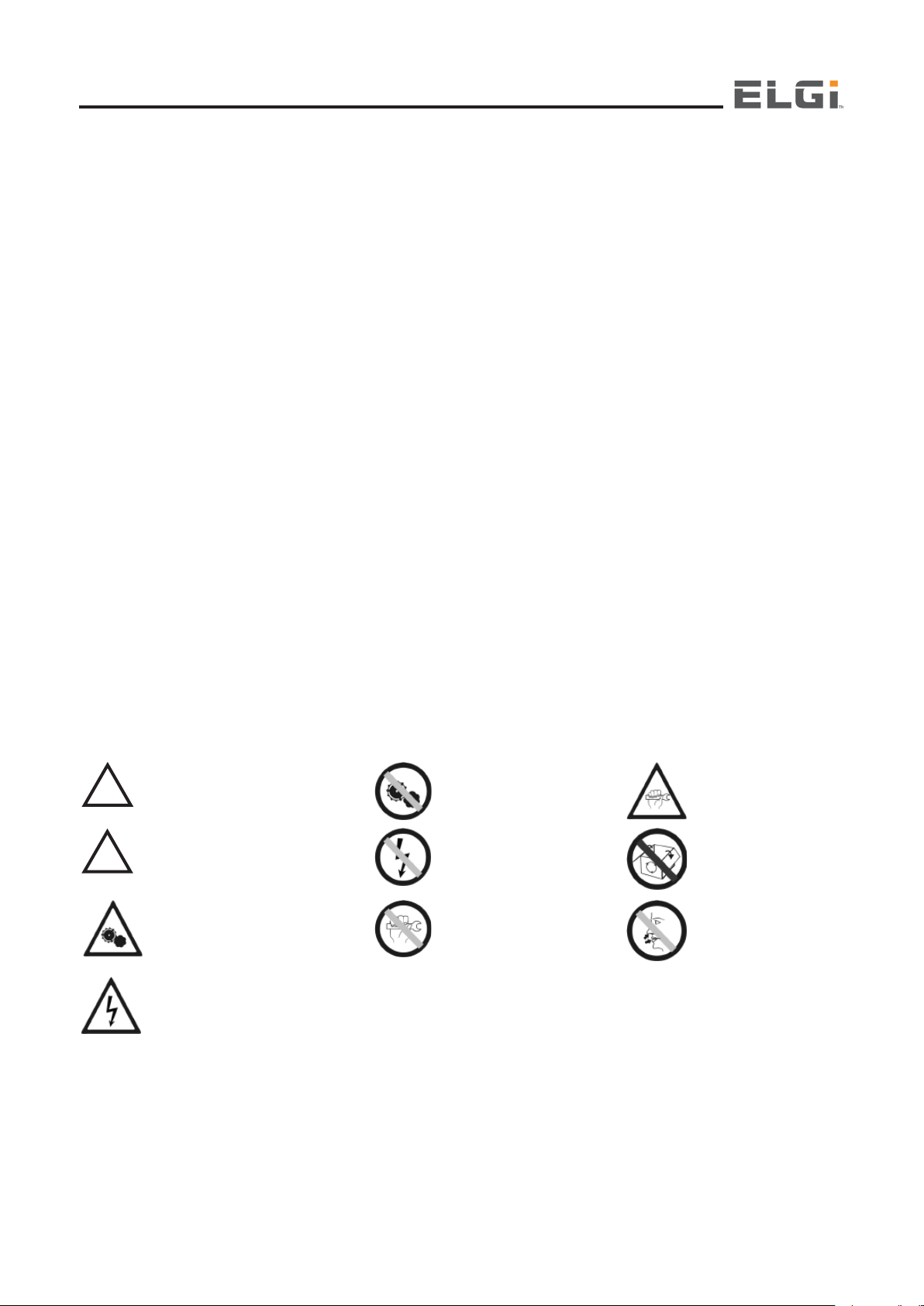
Definitions and Symbols
This information is related to your safety and also to preventing any problems relevant to equipments used. To help you
recognize this information, we use the following symbols
NOTE:
Note clarifies procedures or conditions which may otherwise be misinterpreted or overlooked. Note may also be used to clarify
apparently contradictory or confusing situations.
CAUTION:
Caution is to draw attention to a procedure which, if not done correctly, can lead to equipment damage.
WARNING:
Warning calls attention to dangerous or hazardous conditions inherent to the operation, cleaning and maintenance of the
equipment which may result in personal injury or death of the operator or other persons.
SYMBOLS:
!
CAUTION
!
WARNING
CAUTION
WARNING
OPERATION
ENERGIZED
(POWER ON)
DO NOT OPERATE
DE-ENERGISE
DO NOT ATTEMPT
REPAIRS
CAN CARRY OUT REPAIRS
OR ADJUSTMENT
KEEP ACCESS DOORS
CLOSED
DO NOT INHALE
5

Operation and Maintenance Manual
Message from the Managing Director
Dear Elgi Customer,
It gives me great pleasure to welcome you to the family of users of EG Series compressors from Elgi , among the most
sophisticated rotary screw air compressors available in the world today.
Elgi has designed your EG Series compressor to be reliable, safe, easy to maintain and friendly to use in meeting your
compressed air requirements. This user manual will enable you to use the EG series compressor optimally. Please familiarize
yourself with all the information it contains.
I look forward to your continued satisfaction as a EG series user. Elgi is honored to be your choice for all your compressed
air needs.
Yours sincerely,
Jairam Varadaraj
Managing Director
6

About Elgi
Elgi, established in 1960, designs and manufactures a wide range of compressors. The company has gained its reputation
for design and manufacture of screw compressors through strategic partnerships and continuous research and development.
Screw compressor elements are manufactured in-house using state-of-the-art machining centres for rotor grinding and machining
castings of various sizes. Elgi’s own eta-V profile rotors ensure energy-efficient compressed air supply for all demanding
applications. Elgi is one of the few companies capable of manufacturing wide range of airends and compressor packages in
the world. Elgi’s patent portfolio is a testament to the company’s continuous research and innovation capability.
Elgi has modern manufacturing facilities in equipped with advanced high precision grinding machines, turning centres and
CNC horizontal and vertical machining centres. Screw airends are manufactured with the latest rotor grinding technology,
coupled with measurement technology to maintain precise manufacturing tolerances. Elgi’s manufacturing plants are both
ISO and EOHS certified.
Elgi serves the world marketplace. Over two million compressors are powering business in 63 countries worldwide. The
company offers a strong sales and service network with a well-knit distribution network of dealers and distributors worldwide.
Elgi has its own manufacturing facilities in China, France, India and Italy. Additionally, Elgi has warehouse operations to stock
units and parts in Australia, Brazil, UAE and USA.
EG Series
Your EG Series compressor belongs to a family of rotary screw compressors from Elgi. The compressor has only two moving
parts the rotors which are separated by a thin film of oil, so that there is no wear. This also means that the reliability of the
compressor is unsurpassed.
The screw compressor technology ensures that there is no reduction in output capacity even after many years of operation.
It involves a continuous flow of air through helical cavities in the screw and so the compressed air delivery is pulsation free.
The design of the EG Series gives you a compact and self-contained compressor. Because it has no reciprocating parts, it
runs quietly and free of vibrations. The discharge temperature of the coolant oil is low, less than 1950F, under normal conditions
and therefore carbonized oil is not formed in the compressor.
Salient Features
Two-stage air filter
Improved air filter life cycle
Silent package suitable for inhouse operations
Variable capacity control system
High volumetric efficiency
Efficient air-oil separation by OSBIC (Oil Separation By Impact and Centrifugal action)
Reliable fan which works even at high temperature
Isolated cooling system
Robust cooling system
Industrial designed canopy
Compact and occupies less space
Split type oil coolers for easy serviceability
Flush type panels for easy handling
Anti-vibration mounts restricts vibration
Increased life of consumables
Integrated VFD (Variable Frequency drive) and Dryer.
Zero leak flanged joints.
Oil Carry over < 1 ppm
Advanced Neuron II Controller
Globally Certified product - CE / UL and other Country specific approvals.
7
Operation and Maintenance Manual
Safety
The operator should follow the instructions, procedures and decals given in this manual for safe operation
The maintenance personnel should be adequately trained, and have read and completely understood this operation and
maintenance manual
Compressed air and electricity can be dangerous. To prevent injury before attempting any maintenance, be sure to disconnect
the power at the source and the compressor is relieved of all pressure
Ensure that all the protective covers are in place and that the canopy/doors are closed during operation
Remove red colored brackets at the airend, motor and shroud while commissioning the compressor
Danger! Compressed air used for breathing or food processing must meet O.S.H.A. 1910.134 or F.D.A. 21 C.F.R. 178.3570
regulations. Failure to do so may cause severe injury or death.
Do not allow compressed air to come into contact with food and related items unless it is treated specfically.
This air Compressor is intended to be used for generating compressed air for industrial use only.
Never start the compressor unless you know it is safe to do so. Do not attempt to operate the compressor when it
is known to be in an unsafe condition. Examples of unsafe conditions include improper grounding of the machine
and reverse rotation of the motors
!
WARNING
Electrical arcing from compressor components can ignite flammable liquids and vapors which can result in
serious injury. Never operate the compressor near flammable liquids or vapors. If the compressor is used to
spray flammable materials, keep it at least 20 ft away from the spray area
Operating Precautions
Pressure Release
Annual servicing of safety valve and the kit is necessary. The kit should be checked at standard
pressure
Use only the correct tools for maintenance and repair work. Do not exceed the manufacturers’ rated
safe operating pressure for pipes, valves, filters and other fittings.
Open the oil fill cap only when the compressor is not running and is not pressurized. Shut down the compressor
and bleed the receiver tank to zero internal pressure before removing the cap
Vent all internal pressure prior to opening any line, fitting, valve, drain plug, connection or other components
such as a filters. Vent pressure by popping up the safety valve
Keep personnel out of the line of the discharged air when opening hoses or other points of compressed air
discharge
Do not use air at a pressure greater than 35 PSI for cleaning purposes
Use ear Protection when compressed air is vented out.
Do not engage in horseplay with air hoses: serious injury or death may result
!
WARNING
Fire And Explosion
Clean up spills of lubricant or other combustible substances immediately
Shut down the compressor and allow it to cool down. Move sparks, flames and other sources of ignition away. Do not permit
smoking in the vicinity when checking or adding oil
Do not use flammable solvents for cleaning purposes
Keep grounded conductive objects such as tools away from exposed live electrical parts like terminals
to avoid arcing, which might serve as a source of ignition. Keep all terminals clean and tight
Keep electrical wiring and other terminals in good condition. Replace any wiring that has cracked, cut, abraded or otherwise
degraded insulation
Keep oily rags, trash, dry leaves, litter or other combustibles out of and away from the compressor
PULL THE RING TO
RELEASE PRESSURE
SLOT FOR
RELEASING
THE
PRESSURE
8
Do not operate the compressor without a proper flow of cooling air or with an inadequate flow of lubricant or with a degraded
lubricant
Do not attempt to operate the compressor in a hazardous environment of any classification unless the compressor has
been specially designed and manufactured for explosive applications
Moving Parts
Keep hands, arms and clothing away from couplings, fans and other moving parts
Do not attempt to operate the compressor with the fan guards, coupling guards or other guards removed
Keep access doors closed except when making repairs or adjustments
Wear snug-fitting clothing and confine long hair when working around the compressor, especially when hot or moving parts
such as the cooler, the air end, the thermal valve, the main motor or the fan motor are exposed
Keep hands, feet, floors, controls and walking surfaces clean and free of fluid, water or other liquids to minimize the
possibility of slips and falls
Rotating fan blades can cause serious injury. Disconnect power supply before attempting service
Hot Surfaces
Avoid bodily contact with hot oil, hot coolant and hot surfaces
Keep all parts of the body away from all points of air discharge
Keep a first aid kit handy. Seek medical assistance promptly in case of injury. Do not ignore small cuts and
burns as they may lead to infection
Toxic And Irritating Substances
Do not use air from the compressor for respiration
In the event of ingestion of oils, coolants and lubricants used in the compressor, seek medical treatment
promptly. Wash with soap and water in the event of skin contact
Electrical Shock
Keep all parts of the body and any handheld tools or other conductive objects away from exposed live parts of
the electrical system. Stand on a dry or insulating surface and do not contact any other part of the compressor
when making adjustments or repairs to exposed live parts of the electrical system. Make all such adjustments
or repairs with one hand. This minimizes the possibility of creating a current path through the heart
Attempt repairs only in a clean, dry, well lit and ventilated area
Do not leave the compressor unattended with open electrical enclosures. If it is necessary to do so, disconnect the power
to the compressor at the source and lock it out so that power is not inadvertently restored
Disconnect, lock out and tag the power source prior to attempting repairs or adjustments, turning the machinery manually
or handling ungrounded conductors
All electrical installation must be in accordance with recognized electrical codes and any local health & safety codes
Only authorised and qualified trained personnel should carry out any electrical work on the compressor.
Regularly check that all electrical connections are tight and in good condition.
Dos
Read the manual in detail and follow the instructions
Clean the air compressor package regularly
Keep the air filter clean
Use only genuine Elgi spares
Use only clean and recommended lubricants
Maintain correct oil level and use proper tools
Attend immediately to anything unusual in the air compressor
Maintain log book to monitor operation of compressor
Attend repairs / service with qualified technicians only
9
Operation and Maintenance Manual
Don’ts
Neglect the routine attention
Allow any leakage in the system
Keep any tools or loose items on the compressor/other modules and Meddle with any adjustments or settings
Use cleaning agents, when changing oil and do any repair work while the unit is running
Overload the compressor for a long period
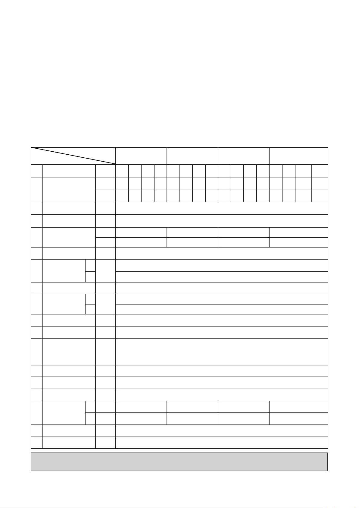
Technical Specification
Standard Compressor
Item
Model
1 Working Pressure psi.g 100 125 150 175 100 125 150 175 100 125 150 175 100 125 150 175
2 Free Air Delivery
Air Discharge
3
temperature
Safety valve set
4
pressure
5 Motor power
6 Type of Motors
Type of Starter for
7
Main Motor
8 Speed of motor rpm 1765
9 Voltage
10 Frequency Hz 60
cfm 71
m3/min 2.01
o
F Ambient Temperature + 18
psi.g
HP 15 20 25 30
kW 11 15 18.5 22
C
-
CV
C
Volts
CV 460
EG 11 (15 HP) EG 15 (20 HP) EG 18 (25 HP) EG 22 (30 HP)
64 57
1.81 1.61
49 92
1.39 2.61
Squirrel cage induction TEFC & Cooling fan integrated motor
85
78 69 116 107
2.41
2.21 1.95 3.28 3.03
205
Automatic Star Delta
Through Variable Frequency Drive
208 - 230/460
2.58
91
80 140 132 112 95
2.27 3.96 3.74 3.17 2.69
11 Speed of fan motor rpm 1490 (208 - 230V) / 1560 (460V)
0.35 (0.26) -208 to 230V
12 Fan Motor Power/Fan
13 Length inch 56
14 Width inch 28
15 Height inch 58
16 Weight
17
Oil recommended
18 Air outlet port size inch
HP
(kW)
C lb
CV
0.39 (0.29) - 460V
11kW - 1 Fan, 15 to 22kW - 2 Fans
1301 1344.8 1499 1521
Ib
1410 1521 1565 1576
ELGI Airlube UT Synthetic
1” NPT Thread
NOTE: C - Standard Compressor, CV - Standard Compressor with Variable Frequency Drive
Tolerance for S.No:3 will be +4OF
10
Commissioning Process
Before the new EG Series compressor is operated for the first time, it needs to be installed at your site according to Elgi’s
Installation specifications.
The servicing technician carries out a series of checks on the machine and the systems to which it is connected to ensure that it
is in a condition to function safely and as desired. He will then describe to the operator of your compressor how the equipment
is to be operated and maintained. This procedure is referred to as the commissioning process.
The commissioning of your compressor ensures that it is installed safely. The general operating conditions of the equipment
including the cleanliness of the atmosphere, the temperature and the ventilation are checked. Technical details relating to
your system such as particulars of your electrical installation are noted. The operator of your compressor is familiarized with
all aspects of both its normal running and dealing with unusual situations.
Please make preparations according to the instructions provided in the Installation section for your EG Series compressor to
be commissioned. Ensure that the location chosen meets the requirements of accessibility, ventilation and safety. Provide
electrical power as recommended in the Installation section. Select air pipe lines and receivers for your system according to
the tables provided in the same section.
Upon completion of the commissioning process the technician will fill in the document known as the commissioning report
and the warranty card.
Unpacking
Unpack the compressor from the packing case by removing the nails. Unscrew the bolts holding the compressor to the base
of the crate
Once all the packing material is removed, check the contents against the packing list. The compressor is shipped with the
following:
Key for doors
Operation and maintenance manual
Checklist of parts of the machine
Electrical drawing
Tools may be provided on request. If any components are found missing, contact Elgi immediately
Installation
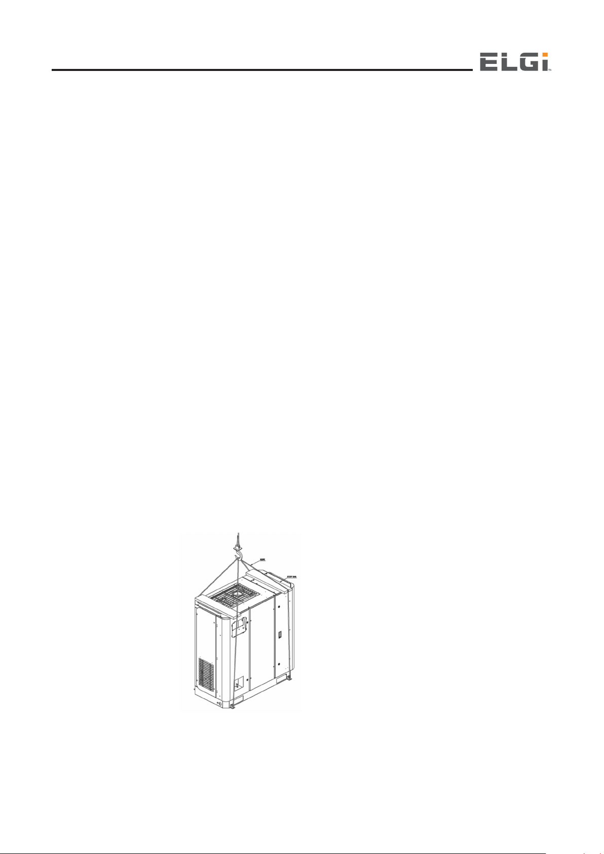
Handling the compressor
EG Series compressors can be lifted either using forklifts or cranes. Please refer to the figures below for general guidance
Option 1
If the compressor is provided with a lifting hook then lift using the hook as shown in image. If no hook is provided, lift it
using slings.
Prior to lifting, inspect the lifting hooks and points of attachment for any cracks in hooks and in welds, any abnormal bends,
corrosion of parts, loosening of bolts & nuts.
11

Operation and Maintenance Manual
Make sure the entire lifting, rigging and supporting structure has been inspected, is in good condition and has a rated
capacity of at least the net weight of the compressor. If you are unsure of the weight, then weigh the compressor before
lifting it.
Make sure the lifting hook has a functional safety latch, or equivalent, and is fully engaged and latched on the hook.
Use guide ropes or equivalent to prevent twisting or swinging of the machine once it has been lifted completely off the
ground.
When the compressor is lifted up by crane, use cushioning materials at he four points of the bottom for prevention of
damaging the cover. Cushion should be padded at 4 lifting points for prevention of damages.
If you are using the guide ropes to lift the machine for installation, Ensure that the rope is not touching the canopy at the
bottom and top to avoid scratches and rope marks or any other severe marks on canopy.
Do not attempt to lift the compressor in high winds. Keep all personnel away from the compressor when it is suspended.
Do not lift the compressor higher than the required height.
Keep the lift operator in constant attendance whenever the compressor is suspended.
Set the compressor down only on level surfaces, capable of supporting at least its net weight plus an additional 10 per
cent allowance.
Option 2
Apply cushion materials for protecting the packaged unit from being damaged. Confirm that the front edge of the fork is
surely put through the holes with the edges of the fork.
Make sure the fork lift is capable of handling the weight of the compressor & its two arms is fully engaged with the compressor
package as shown in image.
Compressor Location – Space Around Compressor
Install the compressor with adequate accessibility to ensure obstruction-free operation and maintenance. Maintain a clearance
around the compressor as mentioned in GA Drawings
Compressor Location – General Requirements
The compressor room or the area around the compressor should be clean, dry, cool and free of dust. The room temperature
for the compressor should preferably be below 115°F. Excessively warm intake air affects the compressed air output. When
the discharge temperature of the compressor (temperature at compression unit) exceeds the factory-set value of 230°F,
the compressor will trip off. Also, the ambient temperature should not drop below +40°F. Provide air supply openings with
adjustable louvers to ensure that the minimum temperature does not drop below +40°F in winter.
Never store combustible materials within a 35ft radius of the compressor. The room housing the compressor must be
equipped with fire fighting equipment. The floor around the compressor must be of non-combustible material.
Compressor should be Rept on a levelled floor .
Remove the Bottom of the Packing case.
Please observe all accident prevention regulations when installing this compressor
!
WARNING
12
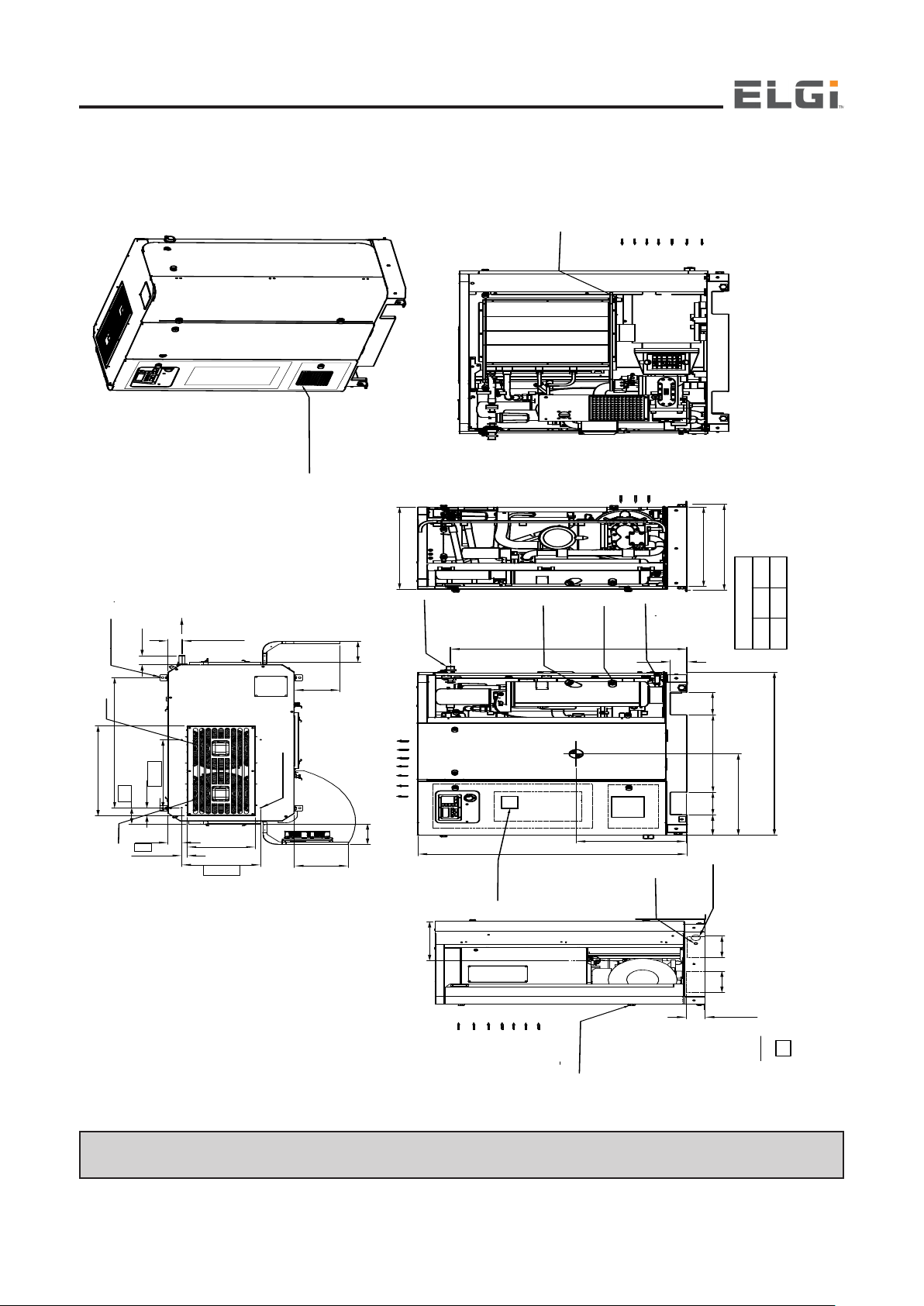
Installation
AIR INLET
(FOR COOLING FAN)
(30"±0.2")
27"
28"±0.4"
X
Y
(8") (27")
(8")
58"±0.4"
51"±0.4"
4"
56''±0.4"
(7")
(7") (7")
Z
MAIN POWER
CABLE ENTRY
Ø1.97"
EARTHING
POINT
DISCHARGE
AIR O UT
G
1
4
" MOISTURE
DRAIN
CENTRE OF GRAVITY
X Y Z
27.95"
23.62" 11.81"
NOTE :
1. Indicates Ducting Dimension
2. 'a' mentioned place for fork lift access
3. 'b' mentioned place for pallet truck access
HOT AIR OUTLET (FROM COOLING FAN)
AIR INLET FOR MOTOR COOLING
1" NPT M ALE AIR
OUT LET PIPE
FAN1
FAN 2
COMPRESSOR
SUCTION
AIR IN
b
b
a
a
VFD DISPLAY
PANEL
3"±0.2"
10"
3"
17"typ
24"typ
45"typ
5.6"
31"
15"
2.8"
1.6"
7"
7"
12"
1.14"
Ø0.59" -4No's
M6x4 For ducting
OIL POUR
OIL SIGHT
GLASS
OIL DRAIN
SIZE G1/2"
VENTILATION
FOR PANEL
OIL DRAIN
(3.6")
GA drawing – EG 11 to EG 22 (15 HP to 30 HP)
NOTE: A minimum of 3.3 ft clearance is required on all sides of compressor and 6.6 ft clearance above the unit.
13

Installation
Ventilation and Exhausting Hot Air
Ensure adequate ventilation in the compressor installation area. Your compressor
has a ventilating air requirement of 247,202 cf/h. The figure provided indicates
different ways in which this could be achieved
If your compressor is fitted with ducts as shown in the figure, the ventilating air
requirement is only a third of the value specified herein
NOTE
• Suspended particulate matter should be less than 150 spm to achieve
the specified consumable life
• No guarantee shall be given if the compressor is operated above
its intended pressure
Operation and Maintenance Manual
Ventilation and Exhausting Hot Air
Ensure adequate ventilation in the compressor installation area. Your compressor has a ventilating air requirement of
247202 ft3/hr. The figure provided indicates different ways in which this could be achieved
If your compressor is fitted with ducts as shown in the figure, the ventilating air requirement is only a third of the value specified
herein
I Possibility II Possibility
B
A
IV Possibility
Natural Forced
NOTE :
A = Intake air aperture with louvres
B = Exhaust air inlet area, should
match the cooler area
Air pressure considered 1 bar.
absolute
Pressure drop in conduit should not
be more than 30 Pa
14.5 psi g
0.00435 psi g
V Possibility
Winter Option
B
Stores
III Possibility
Force & above 5
B
41°F
C
C
A
Summer Option
B
A
NOTE: Suspended particulate matter should be less than 150 spm to achieve the specified consumable life
No guarantee shall be given if the compressor is operated above its intended pressure
Force & above 0
A
C
Follow the guidelines herein for providing ventilation for the compressor
Provide openings close to the floor level on walls/partitions close to the air suction side of the compressor
Provide exhaust openings close to the ceiling for hot air exit
To eliminate transmission of vibrations, provide a soft bellows connector between the duct and the compressor
Contact Elgi in case you need to provide a duct connection or filter fitment on the compressor
The compressor is to be located such that the hot air from other machines is not directed towards it
Provide adequate lights for easy reading of displays and see the parts clearly when doors / panels are opened.
Foundation
An industrial floor with a level surface capable of supporting the weight of the Compressor (refer to the technical specifications)
is sufficient for installing a EG Series compressor.
14
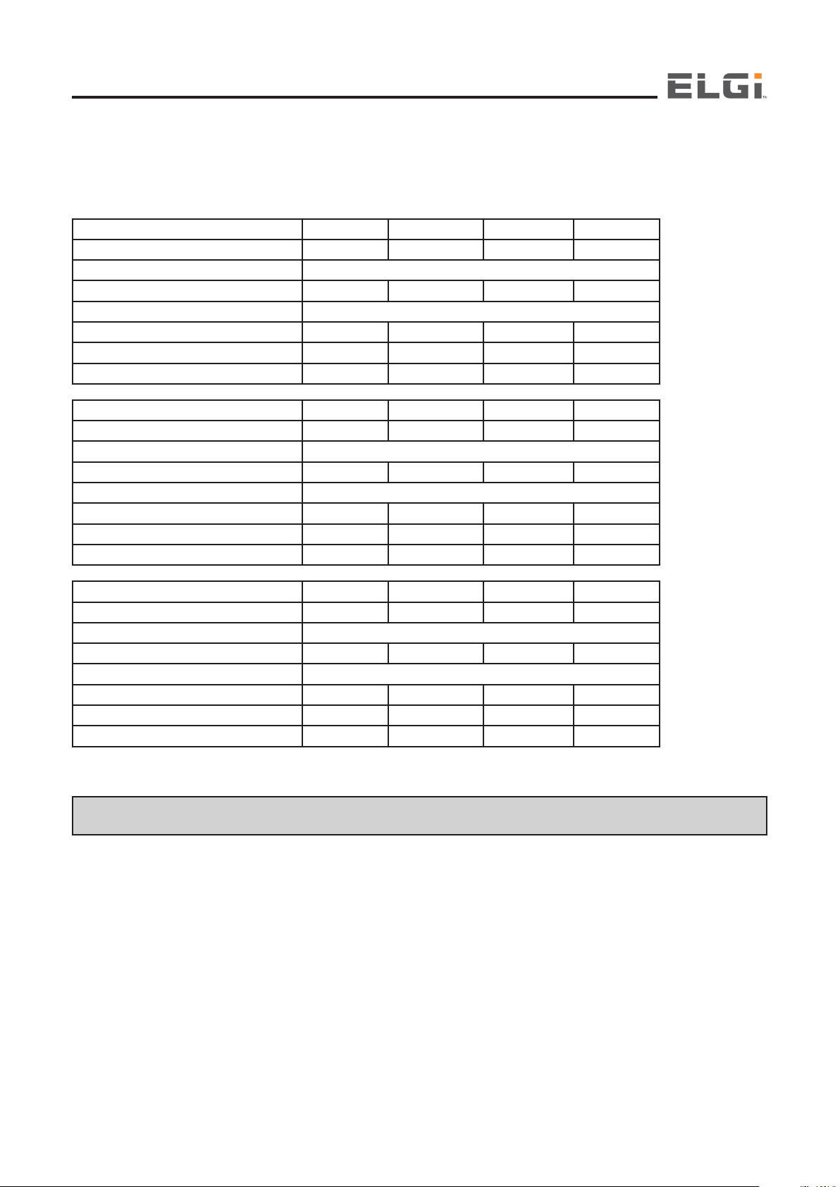
Electricals
You must provide a lockable main switch with pre-connected slow-blow main fuses as per industrial safety regulations. The
power supply should be 460 Volts 3 phase with Earth (PE). The fuse and cable specifications for 460 V, 60 Hz ,3 PH power
supplies are listed in the table below.
Global Series E11 E15 E18 E22
Motor Power (kW/hp) 11/15 15/20 18.5/25 22/30
Power Supply 208V 60Hz 3PH
Nominal Current (A) 45.1 61.6 77.2 92
Cable Material Copper Conductor only
Power Supply Cable (AWG) (L=15ft) 4X8 4X6 4X4 4X4
Upstream fuses (A) (Type RK/CC/J) 63 80 100 125
Switching Fuse Unit (A) 63 100 100 125
Global Series E11 E15 E18 E22
Motor Power (kW/hp) 11/15 15/20 18.5/25 22/30
Power Supply 230V 60Hz 3PH
Nominal Current (A) 43.2 58.6 70.8 84.4
Cable Material Copper Conductor only
Power Supply Cable (AWG) (L=15ft) 4X8 4X6 4X4 4X4
Upstream fuses (A) (Type RK/CC/J) 63 80 100 125
Switching Fuse Unit (A) 63 100 100 125
Global Series E11 E15 E18 E22
Motor Power (kW/hp) 11/15 15/20 18.5/25 22/30
Power Supply 460V 60Hz 3PH
Nominal Current (A) 21.6 28.9 35.4 42.2
Cable Material Copper Conductor only
Power Supply Cable (AWG) (L=15ft) 4X12 4X10 4X8 4X8
Upstream fuses (A) (Type RK/CC/J) 32 40 50 63
Switching Fuse Unit (A) 32 63 63 63
NOTE: Power should be supplied to the compressor through a fuse switch unit of suitable rating mounted within 15 ft of
the compressor
15
Operation and Maintenance Manual
Air Pipe Lines
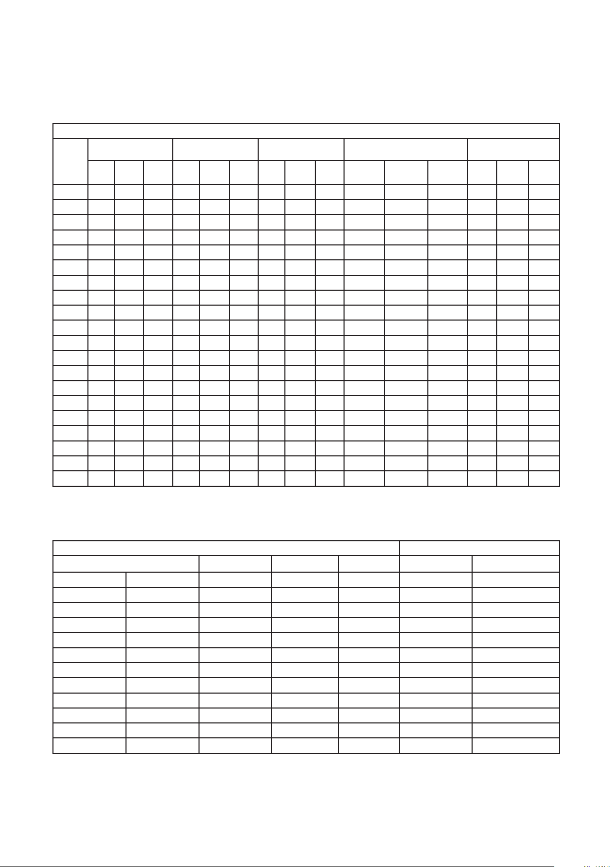
Use the table below as guidance for selecting pipes for your system
Commercial steel pipe size for compressed air line / air pressure losses in 100 ft length
Free
air
(cfm)
10 0.45 0.38 0.31 0.11 0.09 0.08 0.04 0.03 0.02 0.0086 0.0071 0.0058
20 1.74 1.42 1.17 0.41 0.34 0.28 0.13 0.1 0.08 0.032 0.026 0.021 .014 0.12 .010
30 3.84 3.13 2.54 0.9 0.74 0.6 0.28 0.23 0.19 0.068 0.056 0.046 .031 .026 .021
40 6.93 5.55 4.53 1.55 1.28 1.05 0.46 0.38 0.31 0.116 0.096 0.079 .053 .044 .036
50 10.7 8.65 7.01 2.42 2 1.62 0.73 0.6 0.49 0.18 0.046 0.12 .081 .067 .055
60 3.47 2.84 2.33 1.02 0.84 0.69 0.25 0.21 0.17 .12 .095 .078
70 4.73 3.85 3.14 1.36 1.12 0.92 0.34 0.28 0.23 .16 .13 .10
80 6.14 5.01 4.08 1.76 1.44 1.18 0.44 0.36 0.3 .20 .16 .14
90 7.75 6.4 5.17 2.23 1.85 1.49 0.55 0.45 0.37 .25 .20 .17
100 9.62 7.8 6.33 2.69 2.21 1.81 0.066 0.55 0.45 .30 .25 .20
125 15.5 12.4 9.8 4.18 3.41 2.79 1.03 0.85 0.69 .46 .38 .32
150 23 18.1 14.4 5.75 4.19 3.99 1.47 1.2 0.99 .65 .54 .44
175 1.81 6.8 5.45 2 1.64 1.32 .90 .73 .60
200 10.9 8.79 7.11 2.58 2.12 1.73 1.15 .95 .78
250 1.82 1.48 1.20
300 2.55 2.10 1.72
350 3.53 2.86 2.35
400 4.53 3.70 3.03
450 5.80 4.65 3.80
500 7.12 5.79 4.71
1/2 inches 3/4 inches 1 inches 1 1/4 inches 1/2 inches
80 lb100 lb125 lb80 lb100 lb125 lb80 lb100 lb125 lb80 lb 100 lb 125 lb 80lb 100 lb 125
lb
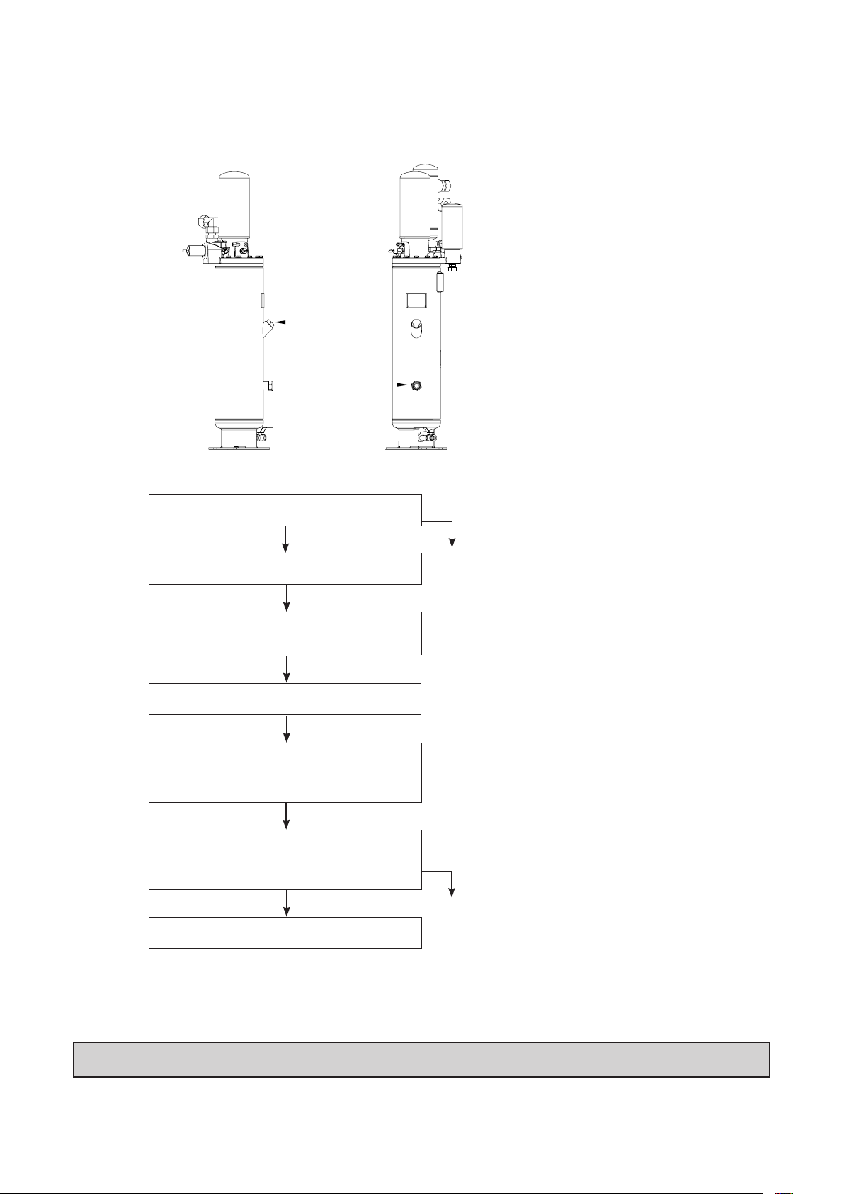
Receivers for Compressed Air Systems
The table below is given for your guidance in selecting an appropriate air receiver for your system.
Receiver specifications Compressed capacity
Volume Height Diameter Weight On/Off control Modulation Control
3
m
0.25 8.83 68.5 25.7 115 Up to 40 Up to 60
0.5 17.66 82.6 30.7 210 41-85 61-120
1 35.32 109.6 39.3 344 86-140 121-235
1.5 52.97 98.4 49.2 783 141-225 236-355
2 70.63 125 49.2 954 226-310 356-470
3 105.95 110.4 61.6 1308 311-445 471-710
4 141.26 141 62.8 1564 446-570 711-945
5 176.58 139.2 70 2129 571-700 946-1180
6 211.89 164.7 70 2343 701-850 1181-1415
7 247.21 143.3 82.6 2885 851-990 1416-1650
8 282.52 156.8 82.6 3115 990-1130 1651-1885
3
ft
inches inches kg cfm cfm
16
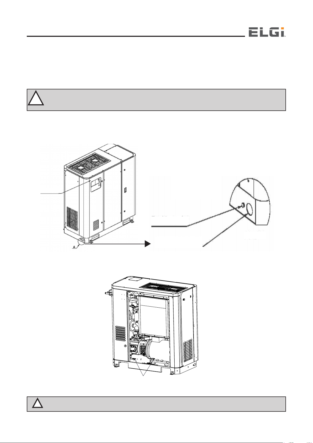
Earthing
Installation
Check the total power supply requirements from the name plate before connecting
the compressor to the electrical lines
Connect the earthing line to the point provided on the base frame at the side of
the compressor
7302 italy change view 7.11
7271 change view :8.11
7226 change view :9.11
7302 italy change view 7.14
7271 change view : 8.14
7226 change view : 9.14
Check the total power supply requirements from the name plate before connecting the compressor to the electrical lines
Connect the earthing line to the point provided on the base frame at the side of the compressor
Connect the leads L1, L2, L3 and PE to the terminals inside the electrical control panel of the compressor as shown in pic
below:
Ensure that only authorized electricians carry out the electrical work. Study the electrical circuit diagram before
!
starting work. Transformer tappings & OLR settings need to be adjusted according to voltage conditions
WARNING
Connect the compressor to the air network
Use Elgi recommended Air lube UT Synthetic oil for optimum performance of the compressor
CONTROL PANEL
(230V / 460V) at site.
EARTHING POINT
POWER CABLE ENTRY
Removal of the Antivibration Mount and shroud Arresting bracket
DETAIL - A
!
WARNING
LOCKING CLAMPS AND LOCKING BOLTS
FOR MOTOR AND AIREND (TO BE REMOVED AFTER
THE COMPRESSOR IS INSTALLED)
Remove AVM arresting brackets from Motor and Airend side once compressor is installed
17
Operation and Maintenance Manual
Oil Fill Procedure
OIL FILLING
Oil filling port
PORT (OVER
(Over fill cap)
FILL CAP)
Oil level
OIL SIGHT
sight glass
GLASS
Fill oil in the oil tank up to over fill cap
Close the oil filling plug
Run the compressor for 10 minutes, until the
thermostatic valve opens
Stop the compressor
Ensure sump pressure drops to atmospheric
pressure & Unscrew the plug only 3 turns to
escape any air in system
Refill the oil in the tank until max level
indicated on the tank and close the oil fill
plug
Initial fill
Second fill
Restart the compressor
Oil Level Check
Oil level should be above oil sight glass after fumes settle down post shutdown
Ensure that the oil level sight glass and eye vision is parallel while checking the oil level to avoid parallelex errors.
NOTE: Refill the oil in the tank if the level falls below minimum level
18
Installation
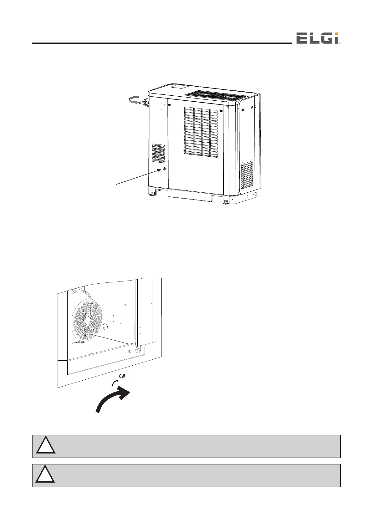
Keep the air outlet line ball valve in fully open condition before starting the compressor
Open
MOISTURE
OUTLET
PORT
Connect the moisture outlet line provided at the side of the compressor as shown in above figure to the waste water disposal line.
Check the direction of rotation of the main motor when starting for the first time by switching ON the compressor (pressing
the green Start button) and switching OFF (pressing the red mushroom Stop button) immediately. The motor must rotate in
the clockwise direction when viewed from the main motor fan cooling side. If the direction of rotation is not correct, isolate the
machine from the electrical lines and interchange any two phases. Re-start the compressor and ensure that the direction of
rotation of the main motor and the fan motor is clockwise
!
WARNING
IMPORTANT
After connecting incoming electrical phase lines, please check
if both the LED’s of Single Phase Preventer (SPP) in the control
panel glow. This ensures correct incoming wiring sequence and
the compressor is ready for start. If it is not set right, flip the
incoming phases for correct wiring sequence
Switch “ON” the compressor after ensuring all the safety points
In case of problems during the running of the compressor, check
which warning LED’s are illuminated on the control panel of the
compressor and refer to the Functional Description and Operation
sections of this manual
If any abnormal noise is heard when the compressor runs, switch
it off immediately and contact the Elgi service engineer for remedy
All the points listed earlier should be followed, when the
compressor is re-installed at a different location
If the compressor has been stored for an extended period before
CLOCK WISE
Ensure that only authorized electricians carry out the electrical work. Study the electrical circuit diagram before
starting the work
commissioning, contact the Elgi distributor.
!
WARNING
Running the compressor in the wrong direction for more than 5 seconds will cause damage to compressor parts
or even total destruction
19

Operation and Maintenance Manual
NOTE: All settings for pressure, temperature, electrical protection devices, etc, are set at factory before dispatch
Extended Storage
If your compressor is expected not to be used for a prolonged period, special measures must be undertaken to ensure the
protection of the following components: the airend, the Motors, and the Air–Oil sump tank
Airend
Remove the airend discharge hose/pipe coupling fitted to the air receiver
Rotate the coupling three times so that the oil present inside the airend comes out through the discharge port
Block the discharge port completely
Remove the inlet rubber duct connected to the intake valve of the air filter assembly
Press the puppet intake valve and pour rust-preventive oil (use Castrol DWX 32 or an equivalent grade) into the airend
through the intake valve
Rotate the coupling five times by hand so that the rust preventive oil spreads all over the bearings, seals and other parts
of the airend
Drain the rust-preventive oil by opening the discharge port plug fully
Refit the hose/pipe coupling on the discharge port
Take care to ensure that all the openings are plugged always to avoid dust entry
This procedure protects the airend for up to six months storage. It must be repeated every six months during storage
Motors
Check the junction box terminals for tightness of the wires
Apply Grease on the motor (use Lithium based or equivalent)
This procedure will protect the motor for up to one year storage
The sump or air–oil separator tank
Remove the entire tank from the compressor after disconnecting it from all hoses, the tank top lid, the minimum pressure
valve outlet line, control pulse lines and control switches
Clean the tank using DW X 32 oil or equivalent
Check the Air–oil separator tank
Replace the oil filter element
Replace the air filter element
The separator tank may now be stored for up to two years.
Flush the Tank, airend with compressor oil and replace the separator element before using the compressor again
Disposal of Packing
The wood used to make the shipping crates of the EG Series compressors is biodegradable.
The polyethylene covers wrapped around the compressor and the polystyrene packing provided around the electrical panels
are not recyclable. They must be disposed of in accordance with prevailing environmental laws.
NOTE: For package preservation / long storage Contact ELGI for further details.
20
Functional Description
Functional Description
Compression in a screw compressor
INLET
DISCHARGE
Compression in a EG Series compressor
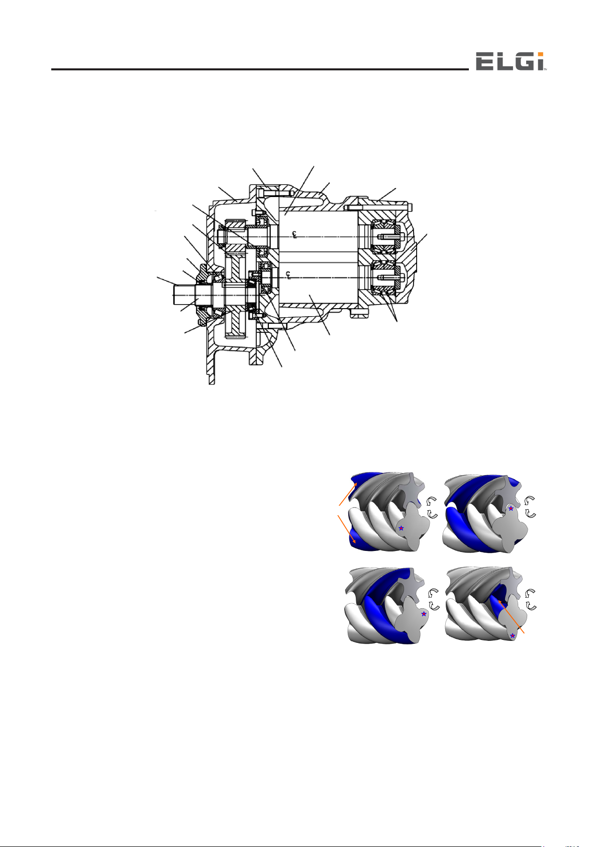
At the heart of the EG Series compressor is the compressor unit or airend, driven by an electrical motor. There are two counterrotating, intermeshed helical screw elements in the airend, the male rotor and the female rotor.
INLET HOUSING
GEAR HOUSING
CYLINDRICAL
ROLLER BEARING
DRIVEN HOUSING
TAPER ROLLER
BEARING
SEAL HOUSING
SEAL
KEY
INPUT SHAFT
DRIVE HOUSING
TAPER ROLLER
MALE ROTOR
ROTOR HOUSING
OF MALE ROTOR
OF MALE ROTOR
FEMALE ROLLER
CYLINDRICAL ROLLER
BEARING
BEARING
OUTLET HOUSING
OUTLET COVER
TOPER ROLLER
BEARING
Gear Drive
The rotors mesh with each other as they turn. Air is trapped between the flutes and lobes of the rotors, getting progressively
compressed as the rotors turn. The compressed air flows out towards the discharge port. One pocket of trapped air getting
compressed progressively is illustrated (next page)
Compression in a screw compressor
In practice, oil is injected in large quantities into the air. It acts as a
coolant, removing the heat of compression. It also serves to seal
leaks between the rotors and the housing, and lubricates the rotors
and the bearings and gears. The oil is separated from the discharge
stream, cooled, filtered and then recycled
Internal cooling using oil permits the temperature at the compression
and to be maintained at approximately 175°F–185°F at an ambient
temperature of 86°F
INLET
DISCHARGE
21
Functional Description
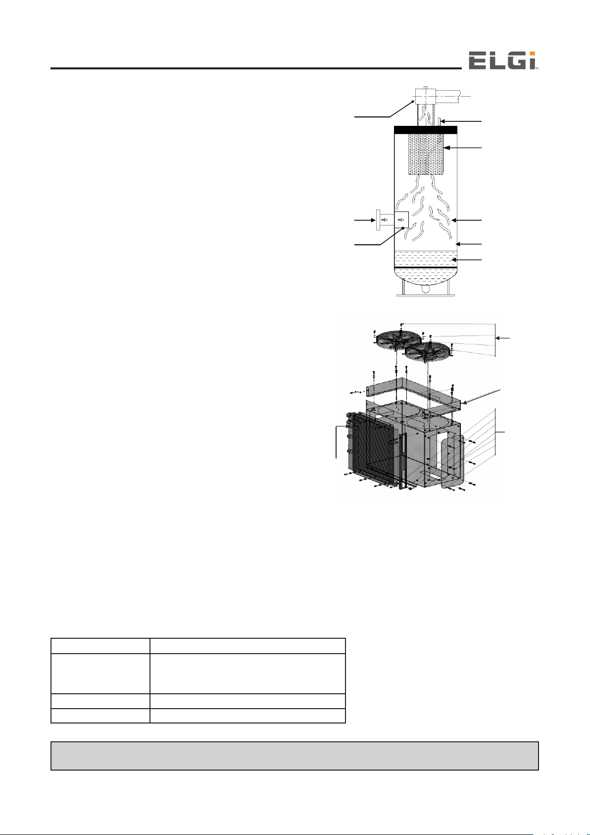
Air Intake System
Air is provided to the airend by the air intake system
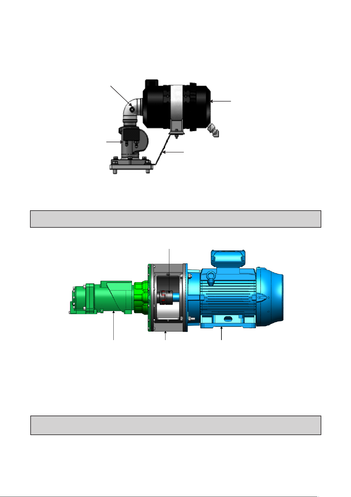
Drive Coupling
Operation and Maintenance Manual
Air Intake System
Air is provided to the airend by the air intake system
AIR FILTER CLOG
Air Filter Clog
INDICATOR
Indicator
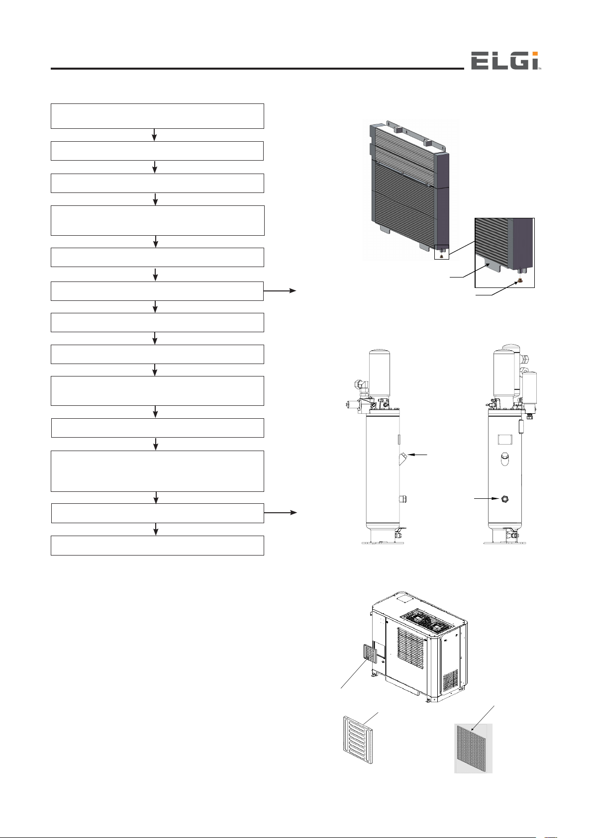
AIR FILTER
Air Filter
INTAKE VALVE
Intake Valve
AIR FILTER
Air Filter
BRACKET
Bracket
The air filter prevents foreign particles like dust from entering the airend. Air gets filtered in two stages by two different filters
namely pre-filter and Air Filter, after which the filtered air enters into the Intake Valve through the Suction hose. The intake
valve controls the amount of air passed into the airend. The Air Filter clog indicator mounted on the Air filter side moves to red
position when the air filter is clogged indicating a replacement of air filter element.
NOTE: Suspended particulate matter should be less than 150 spm to achieve the specified consumable life
No guarantee shall be given if the compressor is operated above its intended pressure
Drive System
AIREND
Electrical System and Controls
The Prime mover of the compressor is Electric Motor, which has an automatic star–delta starter with safety interlocks. Ensure
that the motor rotates in Clock wise direction. when viewing from non - driving side of the motor. The Power is transmitted to
the airend with the help of Claw coupling. The airend derives power from the coupling and Gear, using which it compresses
the incoming air from the Intake Valve.
If no fault is detected in the controller, Ready message is displayed. If any fault is detected, trip warning is displayed. The warnings
are displayed as described in the electrical system
DRIVE COUPLING
ADAPTER RING
MAIN MOTOR
22
NOTE: Power should be supplied to the compressor through a fuse switch unit of suitable rating mounted within 15 ft of
the compressor
Discharge System
Air-Oil Separator element
3
rd
Stage separation
2
n
d
Stage separation
Scavenging line
Tank
Oil
Air oil mixture from air end is subjected to 3 stages of separation in
Air-oil separator tank. To bring the oil content to within the desirable
limits below 1ppm, the air oil mixture is first pre separated with the help
a Deflector. The 2nd Stage separation is a centrifugal action. The Third
stage separation is nothing but where the lean mixture is passed through
a highly efficient separator element. Even after passing through the
Separator element some amount of oil gets collected in the bottom of
it, which is returned to the air end through the scavenging or oil return
line. The air with 1ppm - 3 ppm of oil passes through the minimum
pressure valve (MPV). The minimum pressure valve is positioned
downstream of the oil separator. It maintains a minimum pressure
which is required for the circulation of oil within the compressor unit
during the Starting time. The air temperature at this stage is still higher
than the desired temperature at the Air Oil Sump. So it is cooled in an
after-cooler to a few degrees above the ambient temperature. Before
the air is discharged to the external receiver, moisture is removed with
the use of moisture separator..
Cooling and Lubrication System
The oil separated from the air-oil mixture is cooled in the oil cooler.
A thermal element controls the flow of oil to the cooler, depending
on the temperature of the oil. The cooler is bypassed by the oil if the
temperature is not high enough, as in the case of initial flow when the
compressor is started. The oil is passed through an oil filter which
removes dust and other impurities before it is returned to the Air End.
The oil circulation circuit is operated solely by the differential pressure
and does not require any separate oil pump
As stated previously, the oil has a critical function in the compressor. It
removes the major part of the heat of compression, seals all the areas
in the Air End and lubricates the bearings and gears. The properties
of an oil that determine its suitability for use in the compressor include
its viscosity, wear characteristics, demulsibility, heat resistance and
thermal stability.
Elgi Air lube UT Synthetic oil with the right amounts of additives
under strict quality control checks, ensures satisfactory compressor
performance
A good record of the operating temperature of the compressor is
essential for this. Continuous operation of the compressor at a
temperature above 212°F without changing the oil will lead to varnish
formation and will affect the life of the bearings and the airend.
The below figures are guidelines based on extensive trials in the field.
However, Elgi’s Service Engineers can help you optimize the oil drain
interval for your application based on the operating temperature and
pressure and the environmental conditions
Do not mix different brands or grades of oil, this may lead to oil foaming
and detoriaration in performance or may damage the compressor
COOLER
MINIMUM
PRESSURE VALVE
AIR -OIL
MIXTURE
INLET
st
STAGE
I
SEPARATION
SCAVENGING LINE
AIR -OIL
SEPARATOR
ELEMENT
rd
STAGE
3
SEPARATION
nd
STAGE
2
SEPARATION
TANK
OIL
SHROUD
ASSEMBLY
13.6
COOLING
Cooling
(FAN
Fan
FASTENERS)
&
Fasteners
Shroud Assembly
COOLING
Cooler Box
BOX (FAN
&
FASTENERS)
Fasteners
DOT Status
000998067 (1.3 gal) / 000998068 (5.3 gal)
DRAIN PERIOD (Hours)
Air lube UT Synthetic
/ 000998069 (55 gal)
DOT < 212°F 8000
DOT above 212°F Consult Elgi Dealer
NOTE: Suspended particulate matter should be less than 150 spm to achieve the specified consumable life
No guarantee shall be given if the compressor is operated above its intended pressure
23

Operation and Maintenance Manual
Electrical System
The compressor starter is an automatic star–delta starter with safety interlocks
The compressor can be controlled in all modes (Local, Remote and DCS) by the
Neuron II, a dedicated microcontroller. Neuron II has eight digital inputs, three
analogue inputs and eight relay outputs. The inputs are provided by contact switches,
pressure and temperature transducers. Neuron Il control panel has eight tactile pushbuttons, a 16x2 line alphanumeric LCD for display of compressor status and related
information, and 14 LEDs (Annunciation Window) for user interface. If all the inputs
are normal, the display indicates “READY”
To start the compressor, press the “START” (green) push - button located on the controller. The controller will switch on the
relays in the correct order, and these in turn will energize the delta contactor and the solenoid valve. The LCD display will show
the current status of the compressor. The compressor runs and builds up pressure
To stop the compressor, press the STOP (red) push - button.If the machine trips due to a fault,press the Reset button after
rectification the fault.
Preprogrammed timer functions
Star-delta delay -determines the star-to-delta changeover time; set at any value between 6 and 10 seconds
Delta-to-run (DTR) delay-decides the delay between the delta change over and energizing of the solenoid valve
Standby time (unload monitoring time)-stops the compressor if it is running in unloaded condition for a set time (5 minutes)
and starts the compressor automatically on demand
NOTE: Ensure 24 V AC power supply to controller. Modify the timer settings under m/c settings menu present in
the controller according to requirement. Before starting the compressor, check the following electrically.
Separator element Warning
Indicates that the separator element needs to be replaced. The compressor does not shut down automatically in this situation.
Oil Filter Warning
Indicates that the oil filter element needs to be replaced. The compressor does not shut down automatically in this situation.
High Temperature Discharge
The compressor shuts down automatically and this warning light goes on when the discharge temperature exceeds the preset
value of 230±41ºF.
Main Motor Overload Trip
This warning lights up and the compressor shuts down when the main motor is overloaded.
Fan Motor Overload Trip
The fan motor has internal thermal over load protection which safe guards the fan motor. If the fan motor trips then DOT will
be high and tripped the compressor as high temperature.
Graphic Warning Display
This gives graphically the location of a fault (condition requiring a Warning)
Reset Button
This button must be pressed before restarting the compressor after it has shut down with a warning and remedial measures
have been taken.
Safety System and Interlocking Devices
Your EG Series compressor is equipped with the following devices for reliability and safety:
Discharge Temperature Sensor
This is provided to shut down the compressor if the discharge air– oil mixture temperature reaches a preset value of 230 oF.
The temperature probe is fitted in Air end.
24
Temperature sensor
Temperature sensor
mounting
Pressure sensor wire
routing
Fig 25
PRESSURE
SENSOR
TEMPERATURE
SENSOR
PRESSURE
SENSOR
TEMPERATURE
SENSOR MOUNTING
Minimum Pressure Valve
This valve is fitted at the outlet of the oil separator and opens at a defined set pressure.
This facilitates proper air and oil separation and oil circulation to the airend
Safety Valve
The safety valve relieves the pressure in the air–oil receiver tank when it exceeds 175 psi.g.
Overload Relays for Main Motor and Fan Motor
These relays are fitted on the electrical control panel. They ensure the compressor is switched off
when the power consumption exceeds a set value.
Operation - Control System
Checks Before Starting The Compressor
Fill oil in the oil tank as per the oil filling procedure
Open all doors and visually check the machine for suitability of operation
Open the door of the electrical panel at the front of the compressor and check whether the three phases and Earth cables
are connected securely (L1,L2,L3 and PE wires)
Check the necessary earthing line in the panel / compressor base
Starting The Equipment
Press the start button (green) and check that the main motor turns clockwise (when viewed from the main motor fan cooling
side of the compressor). Ensure correct direction of rotation, If not, Stop the compressor by pressing the stop button (red) on
the control panel.
Starting and Normal Operation Mode
Capacity control system without Variable Frequency Drive Machine:
When the machine is switched ON the motor runs in the Star mode and switched to Delta mode, during this period the inlet
valve remains closed. After switching to Delta mode the solenoid valve energizes and opens the inlet valve and closes the
Blow down valve. Thus the machine is started with reduced load on the motor. Now the pressure in the system goes up and
the minimum pressure valve opens the pressurized air to the discharge.
25
Operation and Maintenance Manual
Capacity control system with Variable Frequency Drive Machine:
When the machine is switched ON, the speed of the motor gradually increases with in 30 seconds (Ramp up time) with the
help of VFD, after which the solenoid valve energizes and opens the intake valve and closes the blow down valve. Thus the
machine is started with much reduced load on the motor. Now the pressure in the system goes up and the minimum pressure
valve opens the pressurized air to the discharge.
Whenever the machine is operated with VFD, the VFD tunes the frequency thereby adjusting the Speed based on the
change in Line pressure.
The incoming flow will automatically reduce because of reduced speed of the motor. Conversely, it increases the speed
when the line pressure goes down below target pressure (working pressure).
Refer VFD setting procedure manual for VFD operations.
Unloading Mode
After reaching the maximum “cut out” pressure (Table -1), the pressure sensor senses the pressure and cuts off the solenoid
electrical supply. As a result of this, the solenoid valve becomes Normally closed (NC) and the blow-down valve opens, which
releases the sump pressure to atmospheric pressure and the intake valve closes. The compressor runs, maintaining the
minimum sump pressure. The blowdown line is connected to the air filter element for auto cleaning. During every unloading
process the blow-down valve releases air, which is routed to the air filter element for cleaning it. This reduces the cleaning
requirements of the air filter
Table - 1
Working pressure (psi) Cut out Pressure (psi)
100 115
125 140
150 165
175 190
Monitoring the Running Condition Of The Compressor
Monitor the indicators on the control panel regularly when the compressor is running. Under the following conditions, the
corresponding warning light on the control panel lights up and the compressor stops automatically:
High discharge temperature
Main motor overload
Fan motor overload
Stopping
Press the “STOP” button (red) on the control panel to stop the compressor
To Change the Compressor Settings
Change the compressor settings using the tactile keypad and the LCD Panel on the controller. (Refer to Appendix
for details of the control panel and interpretation of the message)
26

Maintenance
and allow if to cool for few minutes
tightening, rotate it further by hand for one and half rotation
NOTE
The maintenance of EG Series compressors is minimal but important. The indicators on the control panel of the compressor
gives warnings for servicing the suction filter or oil filter element.
Maintenance Schedule
Daily : Prior to starting the machine, it is necessary to check the oil level in the Air Oil Sump (see Starting the compressor in
the Operation section).If the level is low add the required amount of oil. If the addition of oil becomes very frequent, a problem
has developed which is causing this excessive loss. Refer to the section on excessive oil consumption in the Troubleshooting
section for a probable cause and remedy
Once a routine operation has been made, observe the instrument gauges and be sure they monitor the correct readings for
that particular phase of operation. After the machine has warmed up it is recommended that a general check on the overall
machine and instruments be made to ensure that the compressor is running properly.
Do not remove caps, plugs or other components when the compressor is running or pressurized. Stop
!
WARNING
A check-up is necessary to detect and clean the system of any foreign materials. Carry out the following operations
After every 2000 h of running:
Change the oil filter
After every 4000 h of running:
Change air filter element.
the compressor and relieve all internal pressure before doing so.
After every 8000 h of running:
Change the compressor oil
Change separator element.
Clean Air Oil Sump.
Note: Grease the motor. Use only a lithium based high temperature grease such as Unirex N3 ESSO (SIEMENS) or ESSO
Polyrex EPL (HEBAI) or MOBIL POLYREX EM (WEG). Refer maintenance checklist for greasing intervals.
Maintenance Of Individual Components And Systems
Check all accessories independently to verify that they are functioning as required and replace their components as necessary
NOTE: The number of hours of running after which the filter and separator elements and oil are to be replaced are given
as a guideline for normal operating conditions They may vary depending on actual operating conditions.
Oil Filter
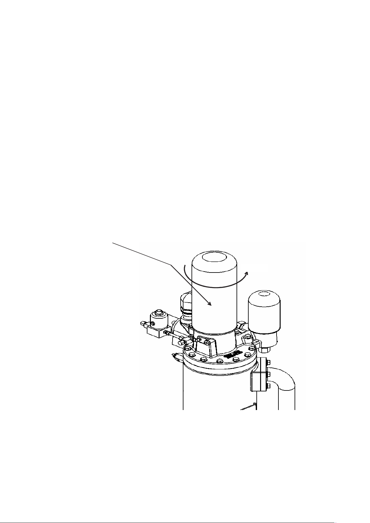
Dismantling Method of Existing Oil Filter
Isolate the machine from the service line, vent the separator tank pressure and
allow if to cool for few minutes
Hold the filter shell and & rotate it counter - clockwise by hand
Assembly of New Oil Filter
Ensure the gasket of the filter is not damaged
Clean the seating surface with clean cotton
Apply this film of oil on the mating surface of the gasket
Return the filter to its original position & rotate it clockwise manually. After
tightening, rotate it further by hand for one and half rotation
Ensure there are no oil leaks from the mating surface
NOTE: Suspended particulate matter should be less than 150 spm to achieve the specified consumable life
No guarantee shall be given if the compressor is operated above its intended pressure
27
ELGI
ELGI
NOTE
Operation and Maintenance Manual
Separator Element
Disassembly of Existing Separator:
Switch off and isolate the machine from service line
Vent the separator tank pressure and allow it to cool for few minutes
Hold the separator outer shell by the removed strap belt & rotate it counter clockwise, until it completely unscrews
The helix adapter should be in the separator head during disassembly
Check the recommended life of oil separator. Once the recommended life is over, it has to be replaced with a new element
Assembly of New Separator
Ensure gasket of the separator is not damaged
Clean the gasket-seating surface with a clean cloth
Apply a thin film of oil on the mating surface of the gasket
Return the separator to its original position & hand rotate it in clockwise direction
Ensure there are no oil leaks from the mating surface. In case of leakage, check the gasket
After tightening by hand, rotate it further
AIR OIL SEPARATOR SHELL
OPEN
28
Oil Change Procedure
Switch off the machine.
Refer the Pre-Filter Cartridge Removal & Insert Procedure.
Hold or fix the Prefilter assembly in cleaning area.
Clean pre-filter with compressed air at less than 2.5 bar g from the reverse
or back side of the Pre-Filter Cartridge.
In case of Major Dust / Dirt accumulation in the Prefilter element, Wash
with clean water or light detergent.
Do not use any Acidic / Alkaline chemicals for cleaning.
Repeat this process based on dust conditions or regular periodic intervals.
Prefilter cartridge
Prefilter element
Prefilter cartridge
Oil filling port
(Over fill cap)
Oil level
sight glass
Switch Off the Compressor and wait for 5 mintues until
the compressed air in the system vented out
Drain oil from the oil tank through the drain ball valve
Drain oil from the cooler through the drain
Drain oil from the airend discharge pipe after
dismantling it
Drain oil from the airend by hand rotation
Add fresh oil. Fill it upto the oil fill plug
Close the oil fill plug
Pour oil into airend & restart the compressor
Initial fill
COOLER
DRAIN PLUG
Allow it to run for about 10 minutes, until the
thermostatic valve opens
Stop the compressor
Unscrew the oil filling plug after 5 minutes so that
residual pressure in the tank is vented out through
bleed hole in the oil fill plug
Refill the tank fill it upto the oil fill plug
Restart the Compressor
Pre - Filter
Cleaning & Maintenance Instructions
Switch off the machine.
Refer the Pre-Filter Cartridge Removal & Insert Procedure.
Hold or fix the Prefilter assembly in cleaning area.
Clean pre-filter with compressed air at less than 2.5 bar g
from the reverse or back side of the Pre-Filter Cartridge.
In case of Major Dust / Dirt accumulation in the Prefilter
element, Wash with clean water or light detergent.
Do not use any Acidic / Alkaline chemicals for cleaning.
Repeat this process based on dust conditions or regular
periodic intervals.
OIL FILLING
PORT (OVER
FILL CAP)
OIL LEVEL
SIGHT GLASS
Second fill
29
Maintenance
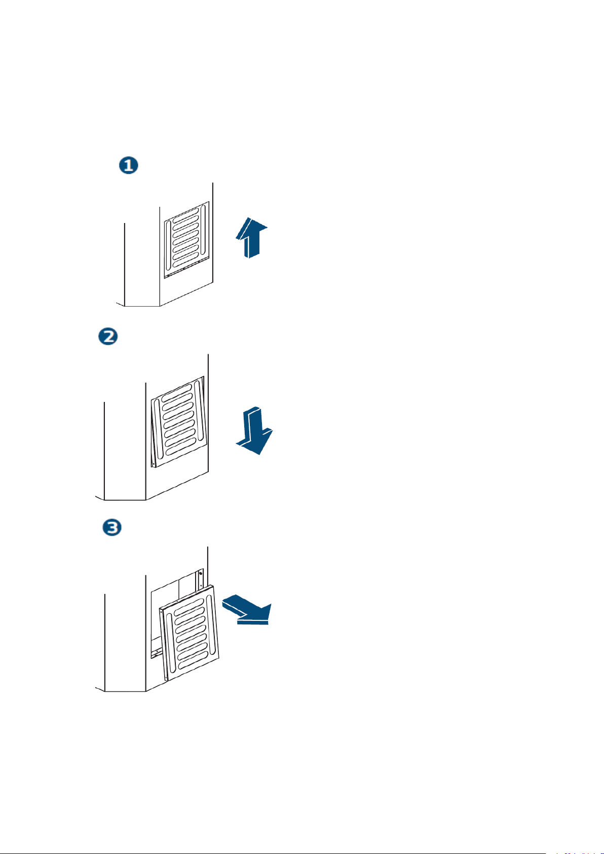
Suction Pre-filter Cartridge Removal Procedure
1. Slide Upward
Hold the pre-filter between the louvers and
slide upwards slightly until the pre-filter
bottom edge is visible
2. Slide Downward
When the pre-filter bottom edge is visible,
slant the pre-filter forward
and slide it downwards away from the
equipment
3. Pull Forward
When the top and bottom edges of the
pre-filter are free from the equipment,
move the pre-filter forward to remove
completely.
Suction Pre-filter Cartridge Insert Procedure.
Note : For insert sequence procedure from 3-2-1
Operation and Maintenance Manual
30
 Loading...