

Elgas miniELCOR SCR1, miniELCOR Operation Manual
GAS-VOLUME CONVERSION DEVICE
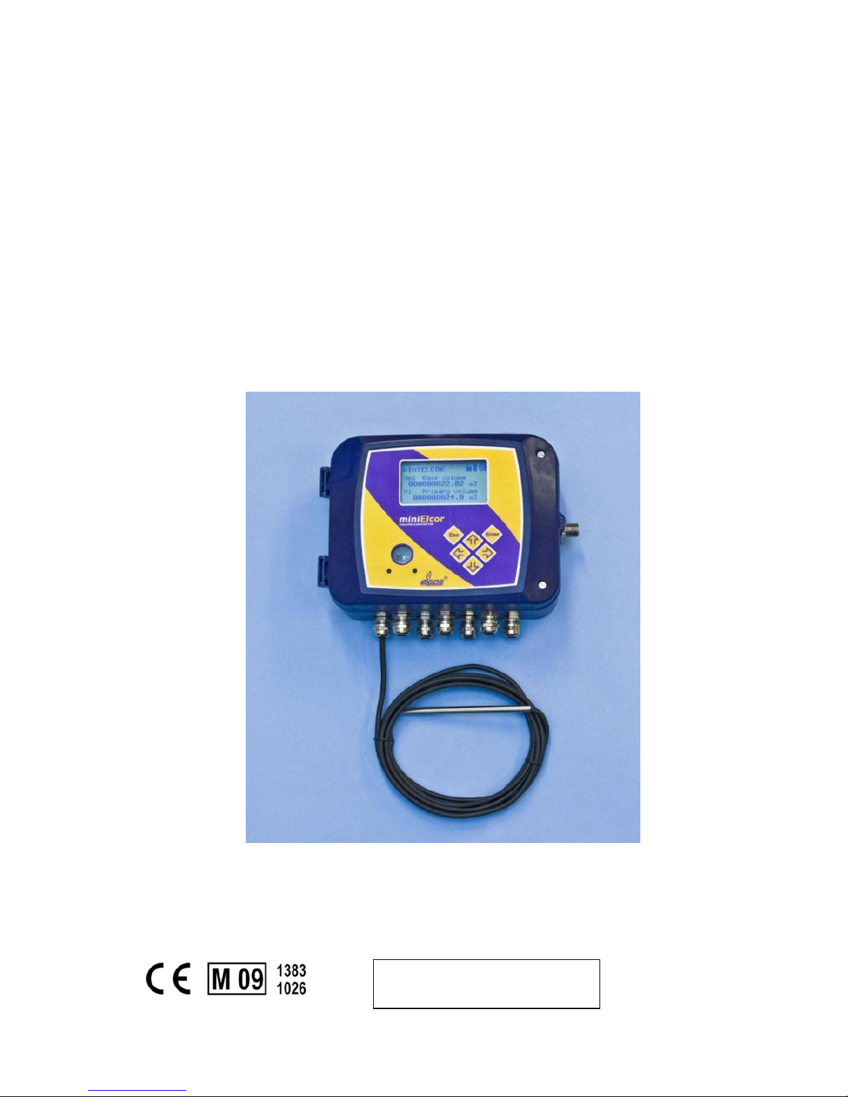
miniELCOR
Device Description
Operation Manual
Technical Description
Mounting instructions
Device settings
Single-channel conversion device of gas volume at measurement conditions to
volume at base conditions. Approved for installation in potentially explosive
atmospheres.
January 2010
Rev. 6g
PRELIMINARY

Safety Measures
This measurement device can be operated only by an operator trained in
compliance with the technical terms, safety regulations, and standards. It is
necessary to consider any other legal and safety regulations stipulated for special
applications. Similar measures also apply for special applications. Similar measures
also apply for using the accessories. The operator training must be in compliance
with Decree no. 50.1978 Coll.
The information in this manual does not have the burden of a legal obligation from the
manufacturer’s side. The manufacturer reserves the right to implement changes. Any
changes in the manual or in the product itself can be performed at any time without any
previous alert, with the goal of improving the device or fixing any typographical or technical
mistakes.

TABLEOFCONTENTS
1
Introduction.............................................................................................1
1.1 Basicdevicedescription........................................................................................1
1.2 Functionprinciple..................................................................................................2
1.3 Devicedimensions.................................................................................................7
2 Devicetechnicaldescription.....................................................................7
2.1 Devicearchitecture...............................................................................................7
2.2 Devicepowersupply.............................................................................................8
2.3 Securitymarks.....................................................................................................11
2.4 Productlabel.......................................................................................................13
3 Safetyinstructions...................................................................................14
3.1 General...............................................................................................................14
3.2 Useinpotentiallyexplosiveatmospheres...........................................................14
3.3 Risksofusage......................................................................................................14
3.4 Specialconditionsofuse.....................................................................................15
3.5 Usingdevicevariantsfordifferentgroupsofgas.................................................15
4 Metrologycharacteristics........................................................................16
4.1 Measuringtemperature......................................................................................16
4.2 Measuringpressure.............................................................................................16
4.3 Compressibilitycalculation..................................................................................17
4.4 Volumemeasuringandcalculation......................................................................18
5 Connectinginputsandoutputs................................................................21
5.1 Inputs..................................................................................................................21
5.2 Outputs...............................................................................................................25
5.3 Addingofanotherpressureortemperaturetransducer......................................26
6 Communicationwithdevice....................................................................29
6.1 RS‐232andRS‐485interfaces..............................................................................29
6.2 OpticalinterfaceIEC‐1107...................................................................................31
7 Descriptionoffunction............................................................................33
7.1 Measurandmarking............................................................................................33
7.2 Instantaneousvalues...........................................................................................33
7.3 Archives..............................................................................................................34
7.4 Deviceparameterization.....................................................................................37
7.5 Otherdevicefunctions........................................................................................38

7.6 Securingthedeviceagainstachangeofmetrologyparameters..........................38
8 Puttinginoperation................................................................................44
9 Deviceoperation.....................................................................................45
9.1 Keypad................................................................................................................45
9.2 Menusystem.......................................................................................................46
9.3 Mainmenu.......................................................................................................... 49
9.4 Instantaneousvaluesmenu.................................................................................50
9.5 Storedvaluesmenu.............................................................................................50
9.6 Deviceparametersmenu..................................................................................... 51
9.7 Parametersettingsmenu....................................................................................52
9.8 Systemdatamenu...............................................................................................53
9.9 Diagnosticsmenu................................................................................................54
10 Mountinginstructions.............................................................................57
10.1 Mechanicalmountingofthedevice.....................................................................57
10.2 Cableconnection,grounding...............................................................................61
11 Accessories..............................................................................................63
11.1 Assemblyaccessories..........................................................................................63
11.2 Intrinsicallysafesupplysourcesforexternalpowersupply.................................63
11.3 Separationandcommunicationmodules............................................................63
11.4 GPRScommunicators..........................................................................................63
11.5 Otheraccessories................................................................................................63
12 Technicalparameters..............................................................................64
13 Inexplosivenessparameters....................................................................70
14 Devicesetting..........................................................................................72
14.1 Standarddevicecontrolafterinstallation............................................................72
14.2 DeviceconnectionwithPC..................................................................................73
14.3 SettingofcommunicationbetweendeviceandPC..............................................73
14.4 Passwordinthedevice........................................................................................84
15 Configurationexamples...........................................................................86
15.1 Deviceparametersdisplaying..............................................................................86
15.2 Gasmeterconstantsetting..................................................................................86
15.3 Pulseoutputssetting...........................................................................................89
15.4 Analogueoutputsetting...................................................................................... 94
15.5 Setpointsetting–limitvaluesofmeasuredquantity...........................................97

15.6 Settingofexternalpowersupplyfailure.............................................................100
15.7 SettingofcommunicationthroughMODBUSprotocol.......................................101
16 Pressureandtemperaturesensor/transducerreplacement..................105
16.1 Pressureandtemperaturesensor/transducerreplacementprocedurein
miniELCORdevice...............................................................................................105
16.2 Softwaresettingsofdeviceforpropercommunicationwithnewtemperature
sensor.................................................................................................................105
16.3 Softwaresettingsofdeviceforpropercommunicationwithnewpressure
transducer..........................................................................................................108
17 Softwaresettingsofthedeviceforpropercommunicationwithexternal
digitaltemperature(EDT‐34)orpressuretransducer(EDT‐23)..............109
17.1 Addingofdigitaltransducerintodevice’sparameters........................................109
17.2 Addingofquantitymeasuredbydigitaltransducerintodevice’sarchives..........110
18 Finalverificationofthedeviceafterreplacementofsensor/transduceror
addingofdigitaltransducer...................................................................111
19 Whattodoifsomethingdoesnotwork................................................116
20 Literature..............................................................................................119
21 RelevantLiterature................................................................................119
22 Software................................................................................................120
23 Usedtrademarks..................................................................................120
24 Listoffigures.........................................................................................121
25 ListofTables.........................................................................................123

miniELCOR
1
Used symbols and definitions
Symbol Meaning Unit
AGA8-G1 ... Calculation method of gas compressibility factor
AGA8-G2 ... Calculation method of gas compressibility factor
AGA8-92DC ... Calculation method of gas compressibility factor
AGA NX-19 mod ... Calculation method of gas compressibility factor
ASC ... Accredited Service Center
BTS … Base Transceiver Station
CL 1 ... Module for realization of product output 4-20mA
CRC ... Checksum – used for data protection
CTR ... Communication protocol
DATCOM-Kx ... Some of the products of series DATCOM-K (DATCOM-
K1, DATCOM-K2, DATCOM-K3, DATCOM-K3/A,
DATCOM-K4, DATCOM-K4/A)
DLMS ... Communication protocol
DC ... Direct Current voltage
dE … addition (difference) of energy MJ
dV … addition (difference) of primary volume Vm or Vc m
3
dVb … addition (difference) of base volume m3
dVc … addition (difference) of corrected primary volume m3
dVm … addition (difference) of primary volume m3
E … Energy MJ
Es … Estimated value of energy MJ
EDTxx … Digital pressure or temperature transducer EDT 23 or
EDT 34
EMC ... Electromagnetic compatibility and resistance
EMI ... Electromagnetic radiation
firmware, FW ... Software equipment loaded in the device
GOST NX-19 ... Method of gas compressibility calculation ( related with
AGA NX-19 mod) according to VNIMS directive (valid at
temperature range -23°C to +60°C)
GOST
NX-19
Hs
...
Combustion heat MJ/m3
IS ... intrinsic safety, intrinsically safe
JBZ-0x ... Some of the JBZ-01, JBZ-02, JBZ-02/A products
Modbus ... Communication protocol designed by Modicon [15]
M900 ... Specific communication protocol
SGERG-88 ... Calculation method of gas compressibility factor, more
details in Chyba! Nenalezen zdroj odkazů.
SNAM ... Communication protocol
SW ... Software for PC
C ... Conversion factor K ... Ratio of compressibility factors (Z/Zb) kp ... Gas meter constant (number of impulses per 1 m3) imp/m3
N ... Number of input impulses from gas meter imp
p ... Absolute pressure at measurement conditions kPa
pb ... Absolute pressure at base conditions kPa

miniELCOR
2
Notice :
This handbook issue describes device functions with firmware FW 4.xx which is
compatible with previous firmware version 2.xx. All different features will be
mentioned respectively.
Chapters describing new device features of FW ver. 4.xx are marked with (*).
Qm ... Flowrate at measurement conditions ( further primary
flowrate)
m3/h
Qb ... Flowrate at base conditions m3/h
T ... Absolute temperature at measurement conditions (T = t +
273.15)
K
t ... Gas temperature °C
Tb ... Absolute temperature at base conditions K
V ... Volume Vm or Vc
Vm ... Volume at measurement conditions (further primary
volume)
m
3
Vc ... Corrected volume at measurement conditions ( volume
corrected based on correction curve of gasmeter)
m3
Vb ... Volume at base conditions (hereinafter also the
standardized volume)
m3
Vbs ... Error volume at base conditions (hereinafter also the
error standardized volume)
m3
Vs ... Error volume at measurement conditions (hereinafter
also the error operational volume)
m3
Vd ... Difference of primary volume m3
Vbd ... Difference of base volume m3
Vf ... Tariff pulse counter of primary volume
Vbf ... Tariff pulse counter of base volume
Z ... Compression gas factor at measurement conditions
Zb ... Compression gas factor at base conditions

miniELCOR
1
1 Introduction
1.1 Basic device description
The Gas-volume conversion device miniELCOR (hereinafter only “the device”)
is a measuring instrument designed for the conversion of the gas volume measure at
measurement conditions to volume at base conditions.
The information on the gas volume passing through is measured using the
impulse outputs of the gas meter. The gas temperature and pressure are measured
by integrated converters. The device calculates the ratio of compressibility factors of
gas using standard methods or a constant value is used.
The device has been constructed and approved pursuant to the EN 12405-1
standard as a conversion device type 1 (compact system) and can be supplied as a
T, PT, or PTZ conversion device.
From safety point of view device is constructed according to EN 60079-11 like
intrinsic safe.
It is manufactured and supplied in compliance with the following European
Parliament directives:
1994/9/EC Equipment and protective systems for use in potentially explosive
atmospheres
2004/108/EC Electromagnetic compatibility
2004/22/EC Directive on measuring instruments
Device is put onto market and into usage according to above mentioned
standards and is marked with CE mark.
The device is built in a casing with sturdy plastic with IP66 protection. It is
equipped with a graphic display and a 6-button keypad. Furthermore, it has impulse
inputs for the connection of a gas meter with LF or HF impulse output and binary
inputs. Device with FW version 4.xx and higher is suitable for connection via encoder
NAMUR or SCR. If applied encoder SCR the only miniELCOR SCR1 variant is
allowed. The binary inputs can work as check inputs to check the connection with a
gas meter or can have a different function, e.g. monitoring the conditions of safety
snap locks, doors, etc. The device has 4 available outputs. These can be configured
as impulse or binary outputs, or as data outputs for the CL-1 module. When using
this module, an analog current output can be realized.
The device is powered by a lithium battery. The life cycle of the battery is 6
years in the defined work mode. In the case of a battery power supply, one can also
use the impulse outputs. An external power supply source can be used in
applications with higher demands.
The device has a data archive of the measured values with an adjustable
structure and storing period. The binary archive stores changes on the binary inputs
and the occurrence of the monitored events (limits, etc.) Error conditions are stored
in an status archive. It is possible to program the storing of important quantities and
calculations and storage of some statistical values in the daily and monthly archive.
The archive has settings for service and metrology; in case of changes of settings,
the acts influencing the device parameters are recorded. The other logs are available
as well , see more in 7.3.

miniELCOR
2
For communication with its superior system, the device has a serial interface
RS-232 and RS-485. Various communication protocols installed in the device allow
easier connection to the SCADA systems. The device cooperates with common
phone, radio, GSM, and GPRS modems, and in case of an alarm condition, it can
initiate the connection.
The device can be enhanced by one non-metrology converter for measuring
pressure or temperature. This enhancement can be performed without breaking the
official mark on an already installed device.
1) Basic configuration of the device offers following inputs and outputs:
- analog input (pressure P - metrologic channel)
- analog input (temperature T - metrologic channel)
- 4x digital input DI1 to DI4 (binary, pulse); input DI1 can be used for connecting
encoder NAMUR
- 4x digial output DO1 to DO4 (binary, pulse, analog)
- communication channel RS485/RS232 for communication with suprordinate
systém
- input of external power supply
- option: connection one digital pressure or temperature transmiter EDTxx (as
nometrologic) to internal bus by help expansion board KP 065 08. This
enhancement can be accomplished by end user on already installed device
without breaching of metrological seal.
2) Device variant with SCR encoder ensures following inputs and
outputs:
- The same like at basic device variant ( see ad 1) however without possibility
of connection of digital transducer EDTxx
- 1x input for SCR encoder connection by means of extention board KP 065 09
The device can be configured using the supplied SW [22] for PCs. This SW also
allows the readout, display and archive of both the immediate measured values as
well as the contents of the internal device archives.
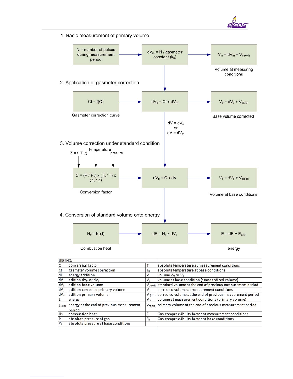
1.2 Function principle
1.2.1 Conversion using equation of state
The device obtains data on the gas flowing through via impulses (N) from an lf
or hf sensor located in the gas meter. The volume at the measuring conditions (V) is
calculated from the number of impulses (N) and gas meter constant (kp).
The device obtains other data on the gas flowing through from the temperature
and pressure converters – gas temperature (t) and absolute pressure at measuring
conditions (p). This data is used to calculate the conversion factor (C) which is
influenced also by these other factors: Absolute temperature at base conditions (Tb),
absolute pressure at base conditions (pb) and compressible factor of the gas at base
conditions (Zb).

miniELCOR
3
Volume at measuring conditions (operational volume):
V =
N
kp
Ratio of compressibility factor:
K =
Z
Zb
Conversion factor:
C =
p
*
Tb
*
1
pb (t + 273.15) K
Volume at base conditions (standardized volume):
V
b
= V * C
Gas compressibility factor expresses the deviation of properties of natural gas
from the properties of an ideal gas. By setting the parameters, it is possible to choose
a specific method for calculation of the compressibility factor pursuant to the standard
(AGA NX-19 mod, AGA8-G1, AGA8-G2, SGERG-88 or AGA8-92DC). A constant
compressibility value can be used for other gases besides natural gas. If the
pressure or temperature value gets out of the limits of validity of the chosen standard
for calculation of compressibility, the device calculates using a default compressibility
value.
The device calculates the gas flow from the impulse frequency on the input in
real time using mathematical filtration from the input signal.
Operational flow:
Q = ∆V / ∆t [m
3
/h]
Where: ∆V ............................ increment of operational volume
∆t ............................. time between the impulses with an accuracy
of one hundredth of a second
The value of the immediate flow displayed on the converter display is updated
every 10 seconds.
Standardized flow:
Q
b
= C * ∆V / ∆t [m3/h]
1.2.2 Error values of volumes at measuring conditions and
volumes at base conditions
For calculation during error conditions (i.e. in case of a converter error,
deviation of the quantity value from the working range, or device error), the device
has counters of the error volume at measuring conditions (Vs) and error volume at
base conditions (Vbs). These counters are interconnected with the pertinent counters
of volume at normal conditions.
A detailed description of device behavior during normal and error conditions is
in Article 4.4.

miniELCOR
4
1.2.3 Volume correction at measurement conditions
Device enables to compensate gasmeter error according to predefined
correction curve from gasmeter test certificate. This function and parameters Vc can
be activated only by manufacturer or by Acreditive service to ensure that used
gasmeter correction curve in dependance on flowrate Qm is valid within working
conditions.
Error of measurement is corrected by usage of function f(Qm). For corrected
volume is:
Vc = Vm x f(Qm)
where
V
c
... Corrected volume at measurement conditions
Vm ... Primary volume
Qm ... Primary flowrate
Linear interpolation method is used for getting values between calibration
points. File with correction values is to be inserted into device with help of service
programme 22. Information about insertion of correction curve into device is logged
in setup archive.
The principle of volume calculation are seen on Fig. 1
Condition for usage of volume correction.
1. Correction is used only in case that gasmeter transmits at least 10 pulses
per second resulting in usage only HF sensors.
2. Under Q
min
correction is not applied and over Q
max
value of correction
coefficient given for Q
max
will be used.
Conversion of volume on energy (*)
Device enables to calculate consumpted quantity of gas directly in energy form.
This conversion uses value of combustion heat H
s
. Calculation is made with
adding of differences dV
b
( and dV
bs)
multiplied by actual value of combustion heat
Hs.
dE=Hs x dVb, dEs=Hs x dV
bs
Two other counters ( energy counter E and estimated energy counter Es) are
dedicated for measurement in configurable energy units: MJ, kWh, Btu.
Note :
No conversion of absolute counter value (E or Es) is accomplished after
change of units. Following increases are added already respecting new units.
Principle diagram of energy calculation is drawn at Fig. 1

miniELCOR
5
Combustion heat Hs
To get correct conversion it is necessary to enter correct value of combustion
heat and relative conditions. Then device will make new conversion of relative
temperature for defined relative conditions and final value will be used for energy
calculation. In case of AGA8-92DC method combustion heat is not entered but
calculated directly from gas composition according to EN ISO 6976. For the other
methods value Hs (MJ/m3) must be entered manually and always under those
relative conditions:
combustion temperature/ temperature of gas = 25°C / 0 °C
miniELCOR
6
Fig. 1 Volume and energy calculations - Scheme
miniELCOR
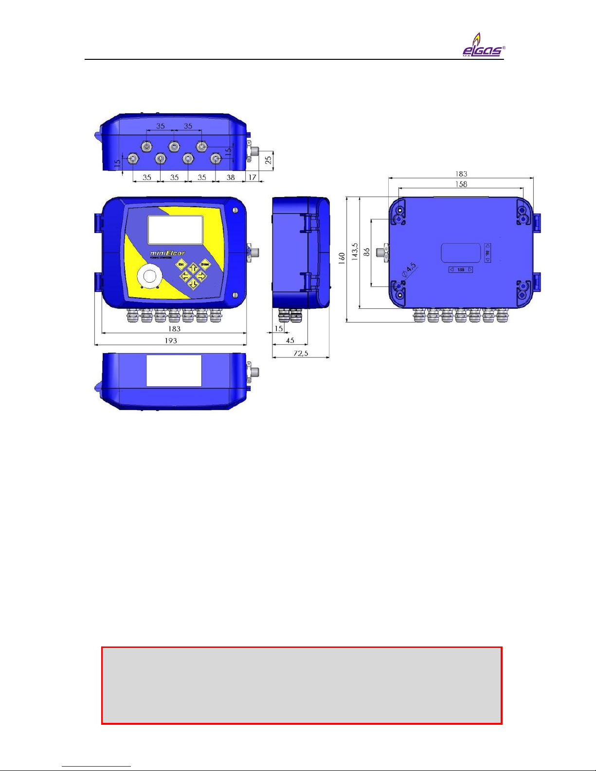
7
1.3 Device dimensions
Fig. 2 Device dimensions
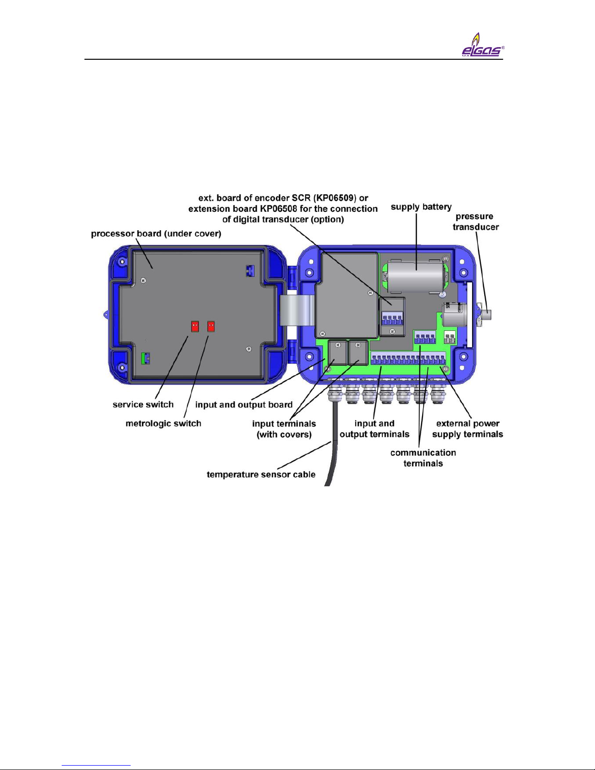
2 Device technical description
2.1 Device architecture
The device’s electronics are laid out on three basic boards.
The bottom part of the casing contains the board of inputs and outputs
containing the battery and back-up battery and terminal box for connecting the
pressure and temperature sensors and any device inputs and outputs. The
connections related to the metrology function of the converter are protected by
covers which are secured with official mark.
Optionally, the input board can have an extension board for connecting an
additional digital pressure (EDT 23 type) or temperature (EDT 34 type) converter.
This additional digital converter communicates with the converter using the protocol
Modbus RTU interface RS-485.
Note:
If SCR encoder is required it can be arranged only by manufacturer
or by authorised service center. Those two subjects will ensure
appropriate labelling placed on housing.
miniELCOR
8
The lid of the housing contains a processor board which is protected by a cover
and secured by an official mark. The board cover has an opening for access to the
service switch. The service switch can be use to enable/disable the setting of the
device parameters using a service SW.
Fig. 3 Main parts of the device
2.2 Device power supply
2.2.1 Supply battery
The device is powered by a built-in battery (lithium) with a voltage rating of
3.6 V. The life cycle of the battery depends especially on the configuration of the
device, the frequency of communication, and the time the display is on. The
consumed capacity is calculated during the device’s activity and the capacity
decrement is recorded in its memory. The device will issue an alert to replace the
battery 90 days before the expected discharge (error messages E9 – see Table 8.

miniELCOR
9
Defined mode with life cycle of the supply battery of more than 5 years:
• Archiving period of the data archive 1 hr
• Communication with device 2 min/day
• Showing on the display 2 min/day
• Period of input impulses ≤10 Hz
• Measuring period 15 s
• Surrounding temperature 25 °C
• expansion board KP 065 09 ( SCR encoder ) is not used
If the device is operated with higher consumption than in the defined mode, it
is necessary to count on a more frequent replacement of the battery or use a network
power source.
2.2.2 Replacement of supply battery
. It is suitable to disconnect the discharged battery as soon as possible. While
the battery is being replaced, the device does not measure pressure or temperature,
but counts the incoming lf impulses (but does not convert the number of pulses, this
will be performed only when the supply battery is connected again) and insures that
the real time clock is running. The data stored in the device archives and parameter
settings will remain preserved.
Discharged batteries belongs at hazardous waste category. According to
OEEZ (2002/96/ES) directives and and other internal directives battery must not be
disposed together with household waste. Withdrawing duty is applied over
discharged battery.
2.2.3 Back-up battery
The battery ensures the back-up of important functions in case of discharge or
replacement of the supply battery. The back-up battery can be replaced in an
accredited service center after the official and security mark is broken (replacement
can not be performed in a potentially explosive atmosphere). It is necessary to use
the same type of battery. Only recommended type of battery may be used.
Due to correct calculation of remaining battery capacity after replacement it is
mandatory to reset this information with service SW tool [22].
Replacement of battery is allowed also at hazardous zone but only with
recommended type of battery.

miniELCOR
10
Defined mode for life cycle of back-up battery of 10 years
• Storing, temperature 25 °C
• Backed-up inputs (DI1 – DI4) not connected or connected contacts
disconnected
• Does not depend on the presence of the supply battery
Defined mode for life cycle of back-up battery of 4 years
• Backed-up inputs (DI1 – DI4) short-circuited
• Without powering battery
Self-discharging of batteries
The back-up and supply batteries are lithium. Their capacity drops due to selfdischarging. The recommended time frame for their replacement is 10 years, even if
the battery was never connected.
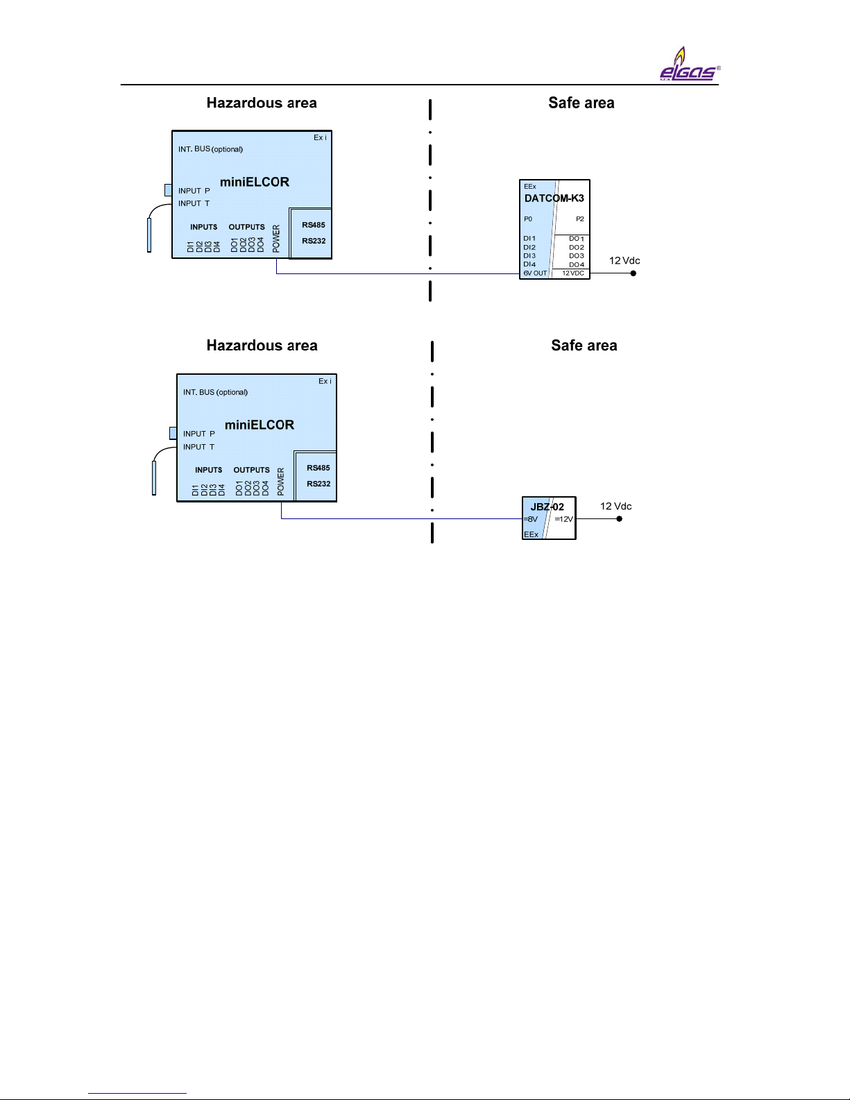
2.2.4 External power supply
Usage of external power supply is necessary in case of appliance of:
- NAMUR HF pulse input
- Binary output
- NAMUR encoder.
External power supply is recommended in case of increased current consumption
regimes like:
- frequent communicationi (more than once a day),
- frequent LCD displaying
- SCR encoder usage.
An approved intrinsically-safe source must be used for the external power
supply. In case a NAMUR type sensor is not connected to the device, one can use
the built-in sources of the communication modules DATCOM-Kx or sources JBZ-01,
JBZ-02.
If the NAMUR sensor is connected to the device, one must always use an
external power source JBZ-01 or JBZ-02.
miniELCOR
11
Fig. 4 Examples of external power supply
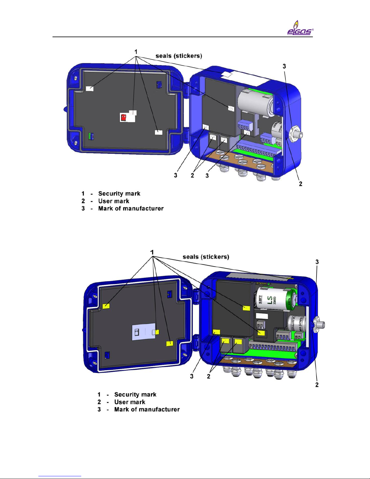
2.3 Security marks
Security marks located on the device indicate the technical condition of the
device regarding unauthorized handling.
Security mark of the manufacturer (metrology mark)
- its design is stipulated by the Approval certificate on the quality management
system for production, output control, and testing pursuant to Enclosure no. 2,
procedure D, ND no. 464/2005 Coll., issued by the Notified person no. 1383. Such
security mark has the same importance for the user as the so called Official mark
pursuant to the Act on Metrology.
In case such a mark is broken, the manufacturer does not guarantee that the
properties of the device are in compliance with the EC Certificate on type verification.
User mark
- control mark of the user (seals) as needed
Mark of manufacturer
- control mark of manufacturer as needed
miniELCOR
12
Fig. 5 Security marks (device without SCR encoder)
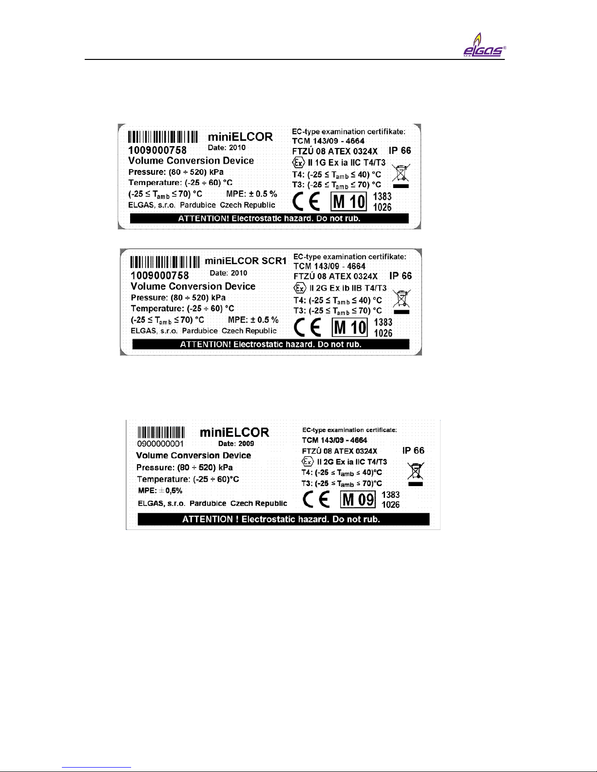
Fig. 6 Security marks of miniELCOR SCR
miniELCOR
13
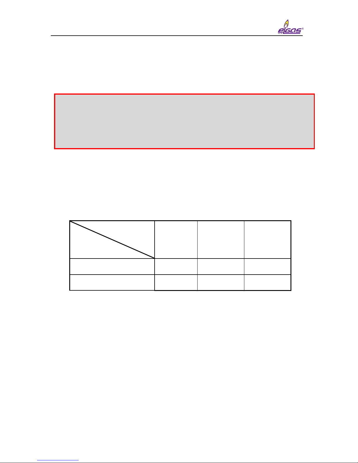
2.4 Product label
Fig. 7 Product label English version
Fig. 8 Product label – original certification for ZONE 1

miniELCOR
14
3 Safety instructions
3.1 General
The device has been approved pursuant to the guideline 94/9/CE and an EC
certificate on type verification (ATEX) has been issued for it’s use in potentially
explosive atmospheres. Respecting this guideline is included in the CE compliance
notation.
3.2 Use in potentially explosive atmospheres
Based on the EC certificate in type verification 08 ATEX 0324X, the device can
be operated in potentially explosive atmospheres with a classification of ZONE1
(potentially explosive atmosphere during normal operation) and ZONE2.
Device is fully in compliance with EN 60079-26 ed.2 (viz [4]) and ATEX
approval 08 ATEX 0324X was extended by Supplement n.3 for hazardous ZONE 0.
Indication of the device regarding safety against explosion:
II 1G Ex ia IIC T4/T3
….
miniELCOR Zone 0
II 2G Ex ib IIB T4/T3
….
miniELCOR SCR Zone 1
Environment temperature for temperature class T4: -25 °C to +40 °C
Environment temperature for temperature class T3: -25 °C to +70 °C
When connecting a device, it is necessary to consider the electrical
characteristics of the connecting cables and abide by the requirements of the
pertinent safety standards. Furthermore, it is necessary to abide by the Special
conditions of use provided these certificates contain them. The parameters of nonexplosiveness of the device are listed in 13.
3.3 Risks of usage
Device cabinet is produced from polycarbonate material. Foil keypad of
polystyrene is placed on top cover. In some extreme cases electrostatic charge
accumulated on surface of cabinet could cause explosion. To avoid explosion it is
strictly recommended to keep the following rules:
The entire device has been constructed and approved as intrinsically
safe. That means that only approved devices (intrinsically safe devices,
consecutive devices) or so called simple devices complying with the
EN 60079-11 standard and complying with the intrinsically safe parameters
listed in the EC Certificate on verification type [16] can be connected to the
device connectors.
The pertinent safety standards must be met when connecting.
miniELCOR
15
• At hazardous zones device must not be installed at places where outer
conditions could create an electrostatic charge.
• Device may be cleaned by humid wiper.
3.4 Special conditions of use
3.5 Using device variants for different groups of gas
Individual variants of device can be used only with certain groups of gas
according to this table.
Group of gas
Device variant
IIC IIB IIA
miniELCOR yes yes yes
miniELCOR SCR no yes yes
1. The device must not be installed and located in an environment with a
potential danger of electrostatic charge of the device casing (e.g. by
flowing air, etc.) Only a damp cloth must be used if the device is being
cleaned, to prevent from creation of electrostatic charge.
2. Only the following types of supply batteries are admissible in the device:
Saft LS33600, Saft LS14250.

miniELCOR
16
4 Metrology characteristics
4.1 Measuring temperature
This device uses the PT1000 temperature sensor to measure temperature. The
temperature sensor’s connection is two-wired. The influence of the length and the
characteristics of the cable used are considered during calibration and therefore do
not influence the accuracy of the temperature measuring.
The temperature measuring range is -25 °C to +60 °C. The measuring period is
common for both the measuring of temperature and pressure and it can be custom
set at a range from 1 s to 30 s. The temperature measuring units can be adjusted.
Replacement of the temperature sensor is protected by the security mark of the
manufacturer (metrology mark) and can be performed solely at an Accredited Service
center (ASC).
During device configuration, the user must enter the constant parameter
Default temperature value. This value will be used for the calculation of
compressibility instead of the measured temperature value in the following cases:
- The value of the measured temperature deviated from the measuring
range
- An error occurred when measuring the temperature
4.2 Measuring pressure
Pressure measuring is ensured by an analog converter. The converter contains
a piezoresistive silicon sensor with a resistant stainless steel membrane. The device
electronics ensures the correction of non-linearity and the temperature dependency
of the pressure sensor based on the calibration data saved in the device memory.
The measuring range of the pressure converter must be requested by the customer
when ordering the device. The available pressure ranges are listed in chapter 12.
The measuring period is common for both the measuring of temperature and
pressure, and can be custom set at a range from 1 to 30 s. The pressure measuring
units can be set.
Replacement of the pressure converter is protected by a security mark of the
manufacturer (metrology mark) and can be performed solely at an Accredited Service
center (ASC).
During device configuration, the user must enter the constant parameter
Default pressure value. This value will be used for the calculation of compressibility
instead of the measured pressure value in the following cases:
- The value of the measured pressure deviated from the measuring range
- The device is manufactured without the pressure converter (so called TZ
or T corrector)
- An error occurred when measuring the pressure
miniELCOR
17
4.3 Compressibility calculation
4.3.1 PTZ, TZ conversion
The compressibility factor is calculated from the composition of the gas listed in
the parameters, using one of the following methods implemented in the device: AGA
NX-19-mod, SGERG-88, AGA8-G1, AGA8-G2 or AGA8-92DC.
Calculation of the compressible factor is performed in each measuring period. In
the SGERG-88 and AGA8-G1 methods the value of the heat of combustion is
entered for the combustion temperature 25°C / gas temperature 0°C. The service SW
contains a built-in calculator for the conversion of the heat of combustion at different
temperatures.
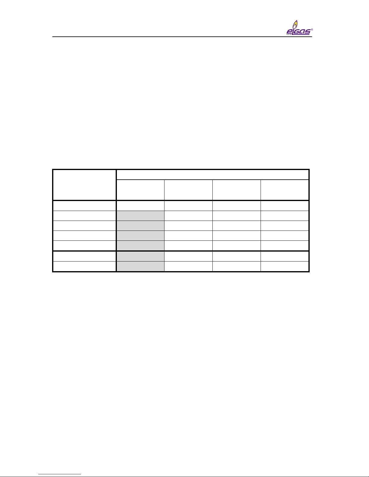
Due to the required accuracy of the device, the use of the individual methods of
calculation of compressibility is limited by the pressure and temperature ranges
pursuant to the following table:
Pressure
measuring range
Method
AGA NX-19
mod
SGERG-88 AGA8-G1
AGA8-G2
AGA8-92DC
80 ÷ 520 kPa -25 ÷ +60 °C -25 ÷ +60 °C -25 ÷ +60 °C -25 ÷ +60 °C
200 ÷ 1000 kPa N/A -25 ÷ +60 °C -25 ÷ +60 °C -25 ÷ +60 °C
400 ÷ 2000 kPa N/A -25 ÷ +60 °C -25 ÷ +60 °C -25 ÷ +60 °C
700 ÷ 3500 kPa N/A -10 ÷ +60 °C -10 ÷ +60 °C -25 ÷ +60 °C
1400 ÷ 7000 kPa N/A -10 ÷ +60 °C -10 ÷ +60 °C -25 ÷ +60 °C
80 ÷ 1000 kPa N/A -25 ÷ +60 °C -25 ÷ +60 °C -25 ÷ +60 °C
400 ÷ 7000 kPa N/A -10 ÷ +60 °C -10 ÷ +60 °C -25 ÷ +60 °C
Table 1 Limitation of standard validity range of compressibility calculation
Note:
At device there is applied compressibily calculation method GOST NX-19 which
is not approved by ČMI certificate.
Usage of method GOST NX-19 is limited only for temperature range from -23°C
to +60°C.
Default compressibility
For the set method during each calculation, it is checked whether the measured
pressure and temperature value are in the valid interval of the pertinent method. If
some of the values are outside the valid interval, the so called default compressibility
is used for the conversion. The value of the default compressibility must be entered
by the user during device configuration.
4.3.2 PT, T conversion
The device also allows the setting of the ratio of compressibility factors (K) as a
fixed constant. The range of the entered constant is not limited.

miniELCOR
18
4.4 Volume measuring and calculation
For measuremet and volume calculation there are used following counters for
each channel.:
Vm - Primary volume counter
Vc - Corrected volume counter (volume corrected based on gasmeter
correction curve)
V - Volume Vm or Vc
Vs - Counter of the operational volume at error conditions (error
operational volume)
Vb - Counter of volume at base conditions (standardized volume)
Vbs - Counter of standardized volume at error conditions
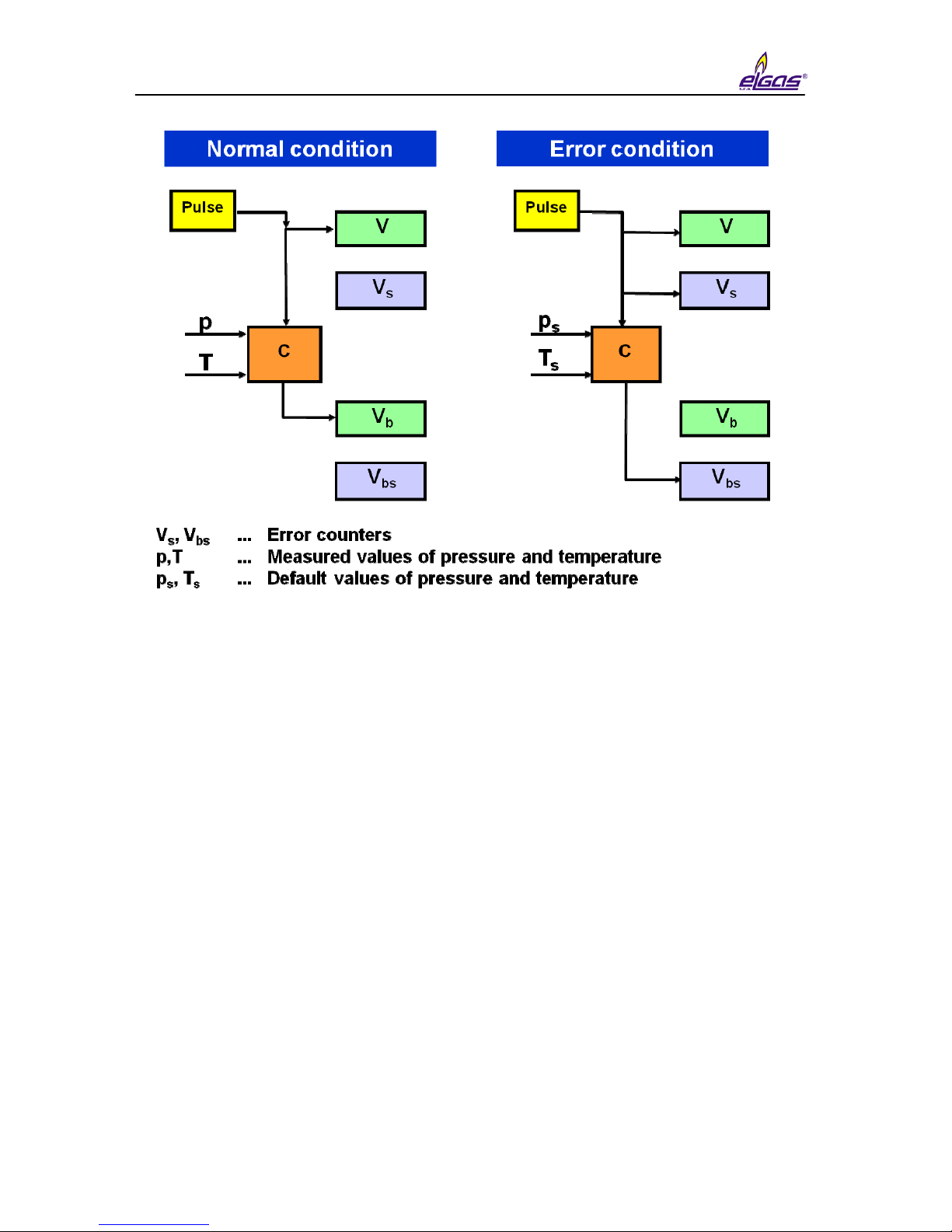
4.4.1 Operation at error conditions
In case of the occurrence of error conditions, the device, at the same time as
counting the impulses in the counter of the volume at measuring conditions (V), starts
to count the impulses in the counter of the error volume at measuring conditions (Vs).
The values of the volumes at base condition (Vb) will stop being counted in the
counter of the volume at base conditions (Vb), and will be counted from the default
values of pressure or temperature and will be stored in the counter of the error
volume at base conditions (Vbs). During this condition, the values are not stored in the
counter of volume at base conditions (Vb).
miniELCOR
19
Fig. 9 Storing impulses in counters
If a default compressibility is used during the calculation for the reason of
deviation of accuracy for the set calculation standard outside the allowed value (see
article 4.3.1), whereas p or t are not outside the measuring range, the converted
volume is stored in the error counter.
If corrected volume V
c
is used primary volume counter can be linked to Vm or
V
c.
at error conditions..
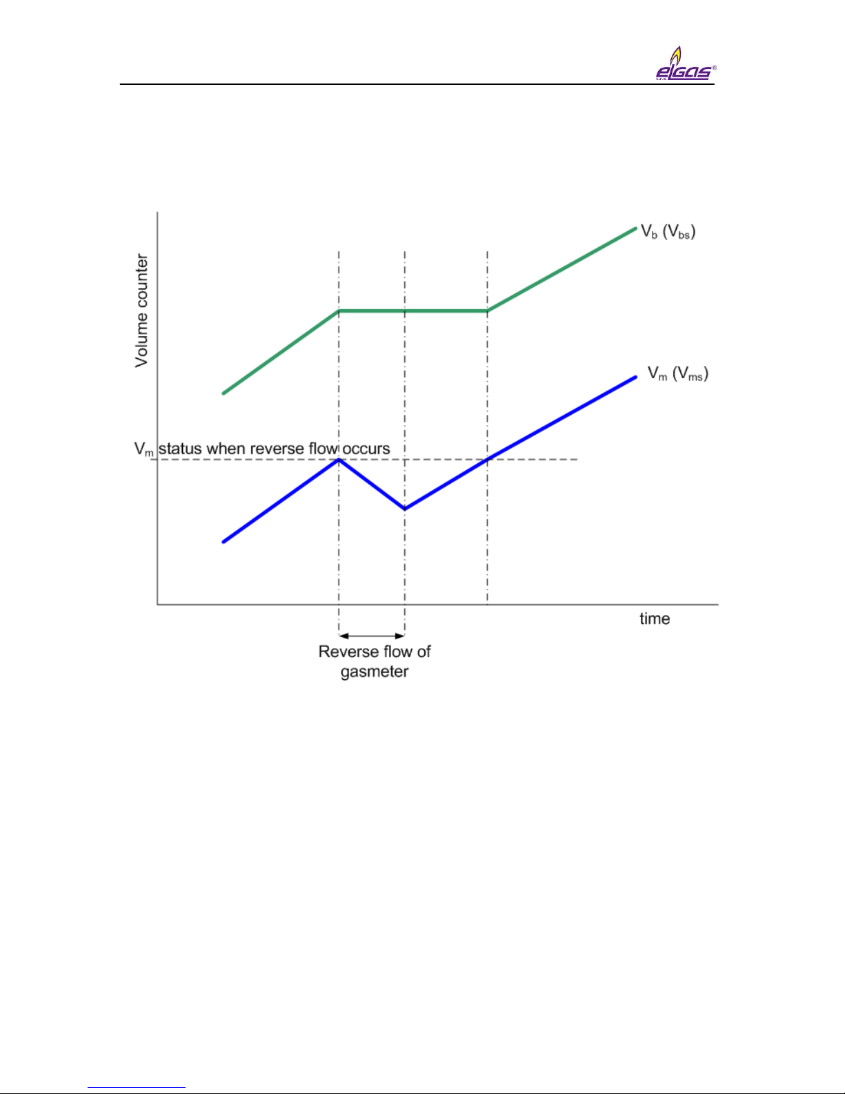
4.4.2 Recognition of gas flow direction change of gas meter (*)
Flow direction detection is enabled for gasmeter equipped with two phases
shifted LF sensors or encoders. Both ways are approved for custody transfer at EC
type approval amendement. Corrector evaluates gas flowrate respecting direction
changes ( Pict. 9) under following terms:
- If primary volume additions are positive in such case volume processing
is made by standard procedure ( for example increasing of Vm and Vb, or
Vms and Vbs).
- If gas flow direction is changed device will fix the value of primary volume
counter at the moment of turn. When gas flows back only primary
volume Vm (or V
ms)
is updated. The other counters are frozen.
miniELCOR
20
- After returning back to correct direction counting will get blocked out into
apropriate counters (Vb, Vbs) only after reaching level of primary volume
where reversed flow was started up. Primary volume counter is equivalent
to gasmeter counter all the time.
Fig. 10 Processing of volumes during reversed flow

miniELCOR
21
5 Connecting inputs and outputs
5.1 Inputs
A total of 4 digital inputs marked as DI1 to DI4 can be connected to the device.
The inputs are brought out at the terminal board inside the device. The digital inputs
can be adjusted using the service SW as a binary or as a LF impulse. The DI1 and
DI2 can also be set as HF impulse or binary type NAMUR. In devices with FW ver.
4.xx input DI1 may be setup also for connection with NAMUR encoder
Input Binary
contact
Binary
NAMUR
LF
impulse
HF
impulse
encoder
NAMUR
DI1 √ √ √ √ √
DI2 √ √ √ √ DI3 √ - √ - -
DI4 √ - √ - -
Table 2 Digital inputs setting options
5.1.1 LF impulse inputs
Serves to read impulses from a gas meter. The flow measuring function can be
chosen for these inputs. The back-up battery ensures preservation of counters’
conditions and reading the impulses of the LF inputs also in case of the discharge or
replacement of the supply battery. After connection of the supply battery, the
impulses read during the outage of voltage of the supply battery are added to the
error counters. The LF impulse input is, on the DI1 and DI2 inputs, connected
between the terminals LF+ and LF- (see Fig. 12).
Changing measuring units, setting the gas meter constant
The measuring units of the impulse inputs can be changed using the service
SW [22]. The conversion constants of the gas meter and S/N of gas meter can be set
using the service SW as well as directly from the device keyboard. When setting the
value of the gas meter constant, only decimal folds or fractions in range from 0.01 to
100 are expected.
Number of places of counters of lf impulse inputs
In the case of lf impulse inputs, the counter works with 9 valid digits, the gas
meter constant influences the size of the maximum number from 9 999 999.99 (for
constant = 0.01) to 99 999 999 900 (for constant = 100).
5.1.2 HF impulse inputs (NAMUR)
The inputs DI1 and DI2 can be configured for processing HF impulses from the
sensors of type NAMUR. Due to the fact that these sensors require a supply voltage
higher than the voltage of the supply battery of the device, the converter must have
an external supply voltage higher than 7 Vdc (e.g. from JBZ-02) for the registration
and processing of HF impulses.
The flow measuring function can be chosen for these inputs. The back-up
battery ensures the preservation of counters’ conditions in case of an outage of the
external supply even in the case of discharge or replacement of the supply battery,

miniELCOR
22
but it does not ensure the counting of the impulses. The terminals for the HF NAMUR
inputs are marked HF+ and HF- (see Fig. 12).
Changing measuring units, setting the gas meter constant
The impulse inputs measuring units and the gas meter constant can be
adjusted using the service SW. The gas meter constant and S/N of gasmeter can be
also set from the device keyboard.
Number of places of counters of the hf impulse inputs
In the case of hf impulse inputs, the counter works with 9 digit places.
5.1.3 Connection with gasmeter via encoder (*)
Gasmeter can be connected with corrector via encoder. Digital value of
gasmeter counter is transferred into EVC. Two types of encoders are supported like
NAMUR and SCR.
The usage of encoders is approved for metrological reasons by EC- type
certificate TCM 143/06-4664, Adition 1.
Encoder NAMUR
No special HW is required for NAMUR encoder usage. The only condition for
NAMUR encoder data processing is usage of IS external power supply JBZ-02 ( or
JBZ-01).
Encoder SCR
To process data from SCR encoder miniELCOR SCR type must be used
complemented with KP 065 09 board. This board must be complemented directly
only by manufacturer. Additional assembly at customer side is not allowed. Encoder
board is connected with input board via IS RS485 Bus ( there is used connector
dedicated for digital transducer connection ( see Pict.3 and Pict.4). This type of
encoder can be also used for only battery powered EVC but it is too much energy
consuming. Enduser should take care about it during parameterisation.
5.1.3.1 Encoder NAMUR input
Connection between EVC and encoder is made with shielded two wires cable.
NAMUR encoder may be connected only via digital input DI1. Terminals for encoder
are the same like for HF pulse input marked HF+ and HF- ( correct signal polarity is
important.). NAMUR encoder connection must be setup in EVC parameters with SW
Telves 22.
5.1.3.2 Encoder SCR input
Connection between EVC and encoder is made with shielded two wires cable
via terminals marked A and B board SCR (KP065 09). No matters on conductor
polarity. Encoder data are transferred into EVC at default measurement period. The
shorter measurement period has bad impact on battery life.
miniELCOR
23
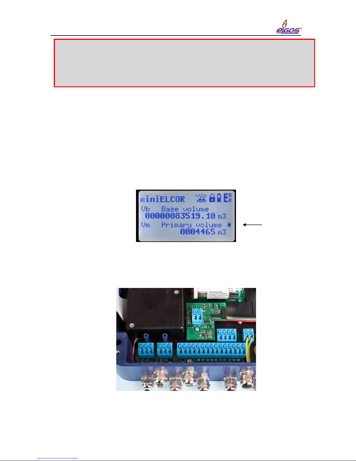
5.1.3.3 Device specification with encoder
Data from encoder are transferred into EVC via shielded two wires cable.
Together with absolute value of gasmeter counter there are transferred other
additional data like S/N , gasmeter constant, number of figures nine for counter
overturning). These additional data are read out with service SW 22 usable at device
parametrisation.
In case of error at communication between EVC and encoder then:
- At actual value primary volume is displayed with asterisk symbol “ * “ .
- If error of communication is longer than 10 min there is volume difference
added into estimated volumes immediately after restart of communication.
Fig. 11 Encoder SCR board (without cover)
If SCR encoder is used at battery regime at standard 30s measurement period
battery life will be decreased down to 2 years.
 Loading...