

Elgas CL-1 User Manual
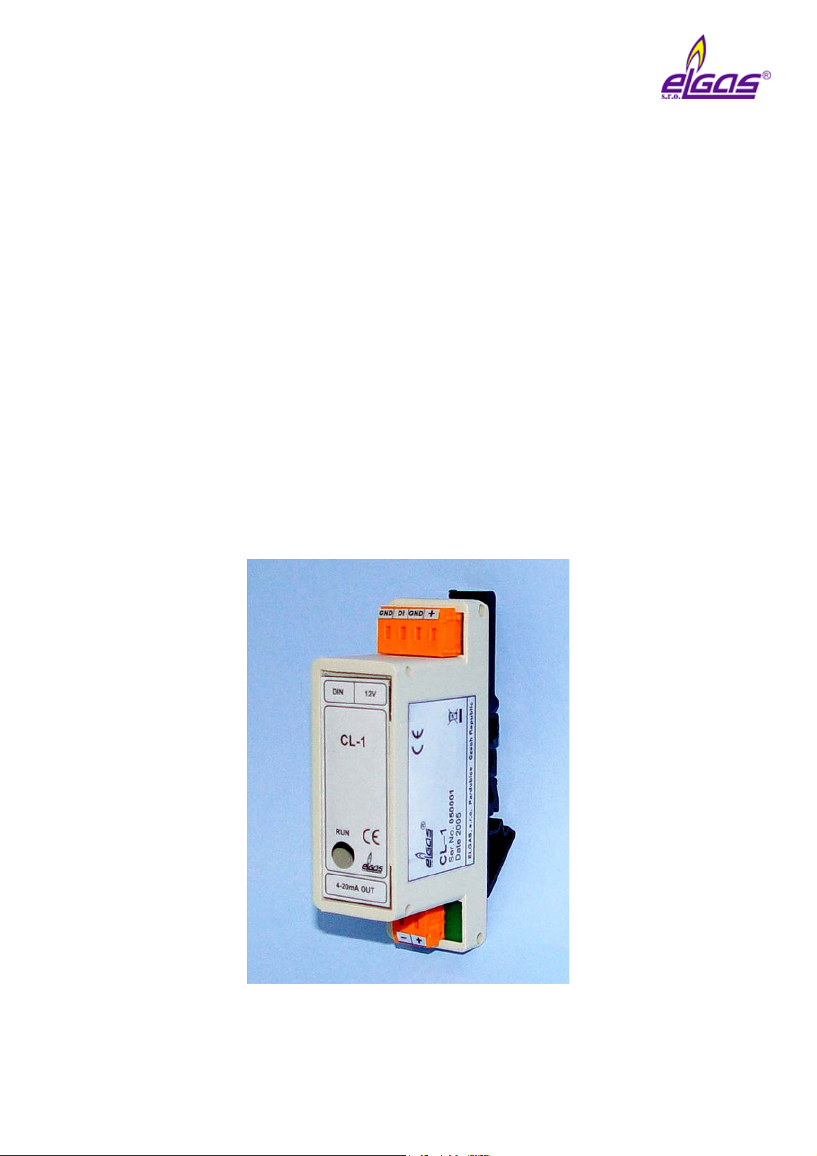
CL-1
Module of current loop
Technical description
Manual
September 2006

CL-1 ELGAS, s.r.o.
Content
1 Technical description .........................................................................................................3
2 Indication of module state.................................................................................................. 3
3 Configuration of module .................................................................................................... 4
4 Technical data .................................................................................................................... 4
Example of connection to digital output of corrector ................................................................ 6
2

CL-1 ELGAS, s.r.o.
1 Technical description
Module CL-1 is a convertor of digital signal on current output 4-20 mA. Module may be
connected to the digital outputs of gas volume conversion device ELCOR-2 and
microELCOR-2. Gas volume conversion devices may generate continuous current output
through CL-1, which is proportional to measured quantities (for example pressure,
temperature, flow rate). It is possible to connect up to 4 analog outputs to the gas volume
conversion device ELCOR-2.
Module has got two galvanic separated circuits – circuit of digital input and circuit of current
output. These circuits require external power supply. It concerns about passive transmitter
from the point of current line.
Output current is controled in the range 3.5 mA – 24 mA. Information about value of output
current is transfered by secured digital communication into module. Period of updating for
output current is given by setting of connected corrector – value of output current is set at the
moment of received data from corrector. Such moment is indicated on module CL-1 by short
light up of green LED diode.
Value of output current may be set through configuration switch on value 3.5 mA or 24 mA
after switch on of the feeding. This value will remain on the output till digital input will
receive new data from corrector.
Module CL-1 is delivered in plastic box for assembly on DIN rail 35 mm. CL-1 is determined
for assembly into switchboard.
2 Indication of module state
For indication of module state is determined green LED diode .
• Status of module
Status of module is indicated through LED diode for time of first 4 seconds after
connection of voltage feeding to the clamps of current output (clamps 4-20 mA OUT).
Whether module is working properly (OK), then LED diode during 4 seconds lights up
after start up. Whether module has got an error, then LED diode will 3x quickly light up
after switch on of the power supply.
• Connection into current line
LED diode lights up after status identification (after expiration about 4 seconds from
connection of voltage feeding to the clamps of current output) till the updating moment of
output current value, when diode will shortly fade and again light up.
• Updating of output current value
LED diode will switch off shortly (about 100 ms) at the moment, when module will
receive valid data on digital input. New information about output current is received by
device. In such moment is value of output current updated.
3
 Loading...