

Page 1

GLOBAL
UNINTERRUPTIBLE
POWER SUPPLY
Model GUPS 2400A–104
Operation Manual
ELGAR ELECTRONICS CORPORATION
9250 Brown Deer Road
San Diego, CA 92121-2294
1-800-73ELGAR (1-800-733-5427)
Tel: (858) 450-0085
Fax: (858) 458-0267
Email: sales@elgar.com
www.elgar.com
©2004 by Elgar Electronics Corporation
This document contains information proprietary to Elgar Electronics Corporation. The information contained herein is
not to be duplicated or transferred in any manner without prior written permission from Elgar Electronics Corporation.
January 23, 2004 Document No. M152332-01 Rev B
Page 2

.
Page 3

ELGAR ONE–YEAR WARRANTY
Elgar Electronics Corporation (hereinafter referred to as Elgar) warrants its products to be free from defects in
material and workmanship. This warranty is effective for one year from the date of shipment of the product to
the original purchaser. Liability of Elgar under this warranty shall exist provided that:
• the Buyer exposes the product to normal use and service and provides normal maintenance on the
product;
• Elgar is promptly notified of defects by the Buyer and that notification occurs within the warranty period;
• the Buyer receives a Return Material Authorization (RMA) number from Elgar’s Repair Department prior to
the return of the product to Elgar for repair, phone 800-73-ELGAR (800-733-5427), ext. 2295;
• the Buyer returns the defective product in the original, or equivalent, shipping container;
• if, upon examination of such product by Elgar it is disclosed that, in fact, a defect in materials and/or
workmanship does exist, that the defect in the product was not caused by improper conditions, misuse,
or negligence; and,
• that Elgar QA seal and nameplates have not been altered or removed and the equipment has not been
repaired or modified by anyone other than Elgar authorized personnel.
This warranty is exclusive and in lieu of all other warranties, expressed or implied, including, but not limited
to, implied warranties of merchantability and fitness of the product to a particular purpose. Elgar, its agents,
or representatives shall in no circumstance be liable for any direct, indirect, special, penal, or consequential
loss or damage of any nature resulting from the malfunction of the product. Remedies under this warranty
are expressly limited to repair or replacement of the product.
CONDITIONS OF WARRANTY
• To return a defective product, contact an Elgar representative or the Elgar factory for an RMA number.
Unauthorized returns will not be accepted and will be returned at the shipper’s expense.
• For Elgar products found to be defective within thirty days of receipt by the original purchaser, Elgar will
absorb all ground freight charges for the repair. Products found defective within the warranty period, but
beyond the initial thirty-day period, should be returned prepaid to Elgar for repair. Elgar will repair the unit
and return it by ground freight pre-paid.
• Normal warranty service is performed at Elgar during the weekday hours of 7:30 am to 4:30 pm Pacific
time. Warranty repair work requested to be accomplished outside of normal working hours will be subject to
Elgar non-warranty service rates.
• Warranty field service is available on an emergency basis. Travel expenses (travel time, per diem expense,
and related air fare) are the responsibility of the Buyer. A Buyer purchase order is required by Elgar prior to
scheduling.
• A returned product found, upon inspection by Elgar, to be in specification is subject to an inspection fee and
applicable freight charges.
• Equipment purchased in the United States carries only a United States warranty for which repair must be
accomplished at the Elgar factory.
Committed to Quality...Striving for Excellence
iii
Page 4
SAFETY NOTICE
Before applying power to the system, verify that the GUPS 2400A–104 is configured properly for the user’s
particular application.
WARNING
Hazardous voltages in excess of 232 VRMS, 328V peak may be present
when covers are removed. Qualified personnel must use extreme caution
when servicing this equipment. Circuit boards, test points, and output
voltages also may be floating above (below) chassis ground.
Installation and servicing must be performed by qualified personnel who are aware of dealing properly with
attendant hazards. This includes such simple tasks as fuse verification.
Ensure that the AC power line ground is connected properly to the GUPS 2400A–104 input connector
or chassis. Similarly, other power ground lines including those to application and maintenance equipment
be grounded properly for both personnel and equipment safety.
must
Always ensure that facility AC input power is de-energized prior to connecting or disconnecting the power
cables. Similarly, the GUPS 2400A–104 circuit breaker must be switched off prior to connecting or
disconnecting output power.
In normal operation, the operator does not have access to hazardous voltages within the chassis. However,
depending on the user’s application configuration, HIGH VOLTAGES HAZARDOUS TO HUMAN SAFETY
may be generated normally on the output terminals. The customer/user must ensure that the output power
lines are labeled properly as to the safety hazards and that any inadvertent contact with hazardous voltages
is eliminated.
Guard against risks of electrical shock during open cover checks by not touching any portion of the electrical
circuits. Even when power is off, capacitors may retain an electrical charge. Use safety glasses during open
cover checks to avoid personal injury by any sudden component failure.
Always disconnect the AC input power and allow three minutes, minimum, before performing any internal
servicing.
Neither Elgar Electronics Corporation, San Diego, California, USA, nor any of the subsidiary sales
organizations can accept any responsibility for personnel, material or consequential injury, loss or damage
that results from improper use of the equipment and accessories.
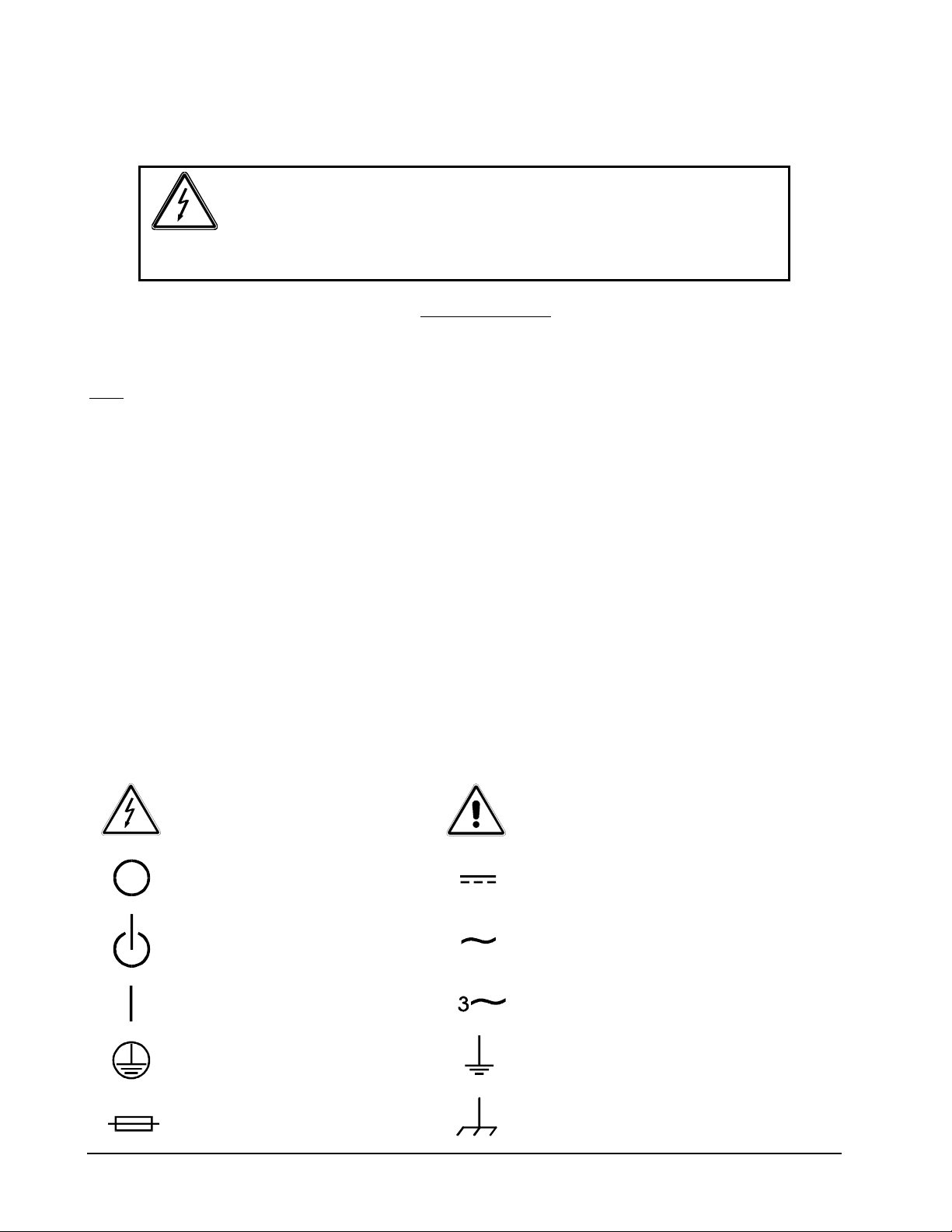
SAFETY SYMBOLS
CAUTION
Risk of Electrica l Shock
Off (Suppl y )
Standby (Supply)
On (Supply)
CAUTION
Refer to Accompanying Documents
Direct Current (DC)
Alternating
Three–Phase
Curre n t (AC)
Alterna ti ng Current
iv
Protective Conductor Terminal
Fuse
Earth (G round) Ter m inal
Chassis Ground
Page 5

CONTENTS
SECTION 1 OVERVIEW AND SPECIFICATIONS................................1-1
1.1 Introduction...................................................................................................... 1-1
1.2 General Description......................................................................................... 1-1
1.3 Specifications...................................................................................................1-1
SECTION 2 INSTALLATION ..............................................................2-1
2.1 Introduction...................................................................................................... 2-1
2.2 Unpacking and Inspection ...............................................................................2-1
2.3 Installation........................................................................................................2-2
2.4 Air Intake and Exhaust.....................................................................................2-2
2.5 Input/Output Connectors .................................................................................2-2
2.6 Wire Gauge Selection......................................................................................2-6
SECTION 3 OPERATION....................................................................3-1
3.1 Introduction...................................................................................................... 3-1
3.2 Control and Indicator Panel.............................................................................3-1
3.2.1 Indicators.............................................................................................3-1
3.2.2 Pushbutton Switches...........................................................................3-2
3.3 Circuit Breakers...............................................................................................3-3
3.4 Audible Alarm .................................................................................................. 3-3
3.5 Control Signals ................................................................................................ 3-3
3.6 Connectors ...................................................................................................... 3-4
3.7 Start-Up and Shutdown Sequences ................................................................ 3-5
3.8 Battery Operation.............................................................................................3-5
3.8.1 Battery Care and Handling ..................................................................3-6
GUPS 2400A–104 Operation Manual v
Page 6

Contents
3.9 RS-232 Data Communications Port.................................................................3-7
3.9.1 Hardware Interface...............................................................................3-7
3.9.2 Software Interface................................................................................3-7
3.9.3 RS-232 Protocol...................................................................................3-8
3.9.4 Test Data Request Commands............................................................3-8
3.9.5 Elgar Terminal Interface (ETI) Data Request Commands....................3-10
3.9.6 Status Words......................................................................................3-11
3.9.7 AC Line Loss Signal...........................................................................3-16
SECTION 4 MAINTENANCE.............................................................. 4-1
4.1 Introduction ......................................................................................................4-1
4.2 Service Information..........................................................................................4-1
4.3 Spare and Repair Parts....................................................................................4-1
4.4 Periodic Maintenance.......................................................................................4-1
4.5 Troubleshooting ...............................................................................................4-2
LIST OF FIGURES
Figure 2–1. GUPS 2400A–104 (Front View)............................................................... 2-3
Figure 2–2. GUPS 2400A–104 (Rear View)............................................................... 2-4
Figure 2–3. GUPS 2400A–104 Dimensions (Top, Side, and Front Views)................. 2-5
Figure 3–1. GUPS 2400A–104 Control and Indicator Panel....................................... 3-2
LIST OF TABLES
Table 2–1. GUPS 2400A–104 Input/Output Connectors............................................ 2-2
Table 2–2. Recommended Wire Gauge Selection Guide........................................... 2-6
Table 3–1. GUPS 2400A–104 Connector Pin Assignments.......................................3-4
Table 3–2. Battery Storage Times.............................................................................. 3-6
Table 3–3. RS-232 Connector Pin-Out....................................................................... 3-7
Table 3–4. RS-232 Communications Port Protocol.................................................... 3-8
Table 3–5. Status Word 1 Data Format....................................................................3-11
Table 3–6. Status Word 2 Data Format....................................................................3-14
Table 4–1. GUPS 2400A-104 Troubleshooting Guide................................................ 4-2
vi GUPS 2400A–104 Operation Manual
Page 7

SECTION 1
OVERVIEW AND SPECIFICATIONS
1.1 Introduction
The Elgar Model GUPS 2400A-104 is a 2400 VA Global Uninterruptible Power Supply (GUPS)
that provides regulated 115 VRMS, 60 Hz output power at up to 20.9 Amps RMS load current.
The GUPS 2400A-104 accepts 3-phase AC input line voltages from 159V to 232V at
frequencies from 370 Hz to 430 Hz. A battery backup of five minutes at 2400 VA output is
provided by a removable battery pack. Output power is continuous when transferring from AC to
battery or battery to AC.
1.2
The GUPS 2400A-104 is contained in a rack-mount enclosure. All input and output connections
are made at the rear panel. Cooling air is drawn in through a filter on the front panel and
exhausted out the rear panel. Operational and input/output power status is indicated by front
panel LEDs. An AC input circuit breaker and control pushbutton switches also are located on
the front panel. There are no operator adjustments.
General Description
1.3 Specifications
(Specifications Subject to Change Without Notice)
AC Input Voltage: 115/200V, 3-phase, 3-wire plus ground, neutral not used;
159V to 232V, line voltage;
92V to 134V, phase voltage
AC Input Current: 9.8A, maximum at 200V, 2400VA/1920W load, fully charged battery;
12.5A, maximum at 159V, 2400VA/1920W load, charging battery
AC Input Frequency: 370Hz to 430Hz
Batteries: 192VDC, sealed, maintenance-free, lead-acid
Battery Hold-Up Time: 5 minutes with a 2400VA/1920W load at 25°C
GUPS 2400A–104 Operation Manual 1-1
Page 8

Overview and Specifications
Battery Recharge Time: 4 hours to 90% full charge following discharge
at 2400VA/1920W and 25°C
Output Voltage: 115V, ±2%
Output Frequency:
Output Current: 20.9A(RMS)
Output Distortion: 2% THD, maximum with linear load
Output Power: 1920W with resistive load;
Efficiency: 77%
AC to Battery Crossover: 159V, maximum low-line voltage;
Battery to AC Crossover: 169V, maximum low-line voltage;
AC Input Voltage Unbalance: 7V (RMS) maximum difference in line voltages
Temperature: 0°C to 40°C (32°F to 104°F), operating;
Humidity: 5% to 95% non-condensing, operating
Altitude: 0 to 10,000ft, operating;
0 to 40,000ft, 2000ft/min, maximum, non-operating
Dimensions: 7"H x 19"W x 25.1"D,
Weight: 75lb (34kg), UPS enclosure;
48lb (22kg) battery module;
123lb (56kg) total weight
60Hz, ±0.1%
2400VA/1920W with a reactive load or a non-linear load
232V, minimum high-line voltage
232V, minimum high-line voltage
-40°C to 65°C (-40°F to 149°F), non-operating
excluding protrusion of handles, controls, and connectors;
fits standard RETMA rack
1-2 GUPS 2400A–104 Operation Manual
Page 9
SECTION 2
INSTALLATION
2.1 Introduction
The Elgar Model GUPS 2400A–104 has been aligned, calibrated, and tested prior to shipment.
The instrument is ready for immediate use upon receipt. However, the following checks should
be made to ensure that the instrument was not damaged during shipment.
CAUTION!
The GUPS 2400A–104 weighs 75 pounds (34 kg) without the
battery pack. The battery pack adds an additional 48 pounds
(22 kg). A minimum two–person lift is required!
WARNING!
Hazardous voltages are present when operating this equipment.
Please read the SAFETY NOTICE on page iv prior to installation,
operation, or maintenance.
2.2 Unpacking and Inspection
Perform a visual inspection of the shipping container prior to accepting the package from the
carrier. If extensive damage is evident, a description of the damage should be noted on the
carrier's receipt and signed by the driver of the carrier agent.
If damage is not apparent until the instrument is unpacked, a claim for concealed damage
should be placed with the carrier. Check for shipping damage such as dents, scratches,
distortion, and damaged connectors. If the instrument or container(s) show signs of rough
handling, remove the covers from the instrument to ensure that the circuit boards are securely in
place and that no loose or broken components are evident.
In addition, the shipping container(s) and filler material should be saved for inspection. Forward
a report of damage to the Elgar Service Department. Elgar will provide instructions for repair or
replacement of the instrument.
GUPS 2400A–104 Operation Manual 2-1
Page 10
Installation
When returning the instrument to Elgar, suitable shipping containers and packing material must
be used. If the instrument needs to be shipped and proper packing material is not available,
contact Elgar to provide containers and shipping instructions.
2.3
The Model GUPS 2400A–104 is 7" (178 mm) high and is designed to be installed in a standard
19" (483 mm) wide cabinet enclosure or a transit case.
Refer to Figure 2–1 through Figure 2–3 for information on outline and mounting dimensions.
2.4
The air intake is located on the front panel of the instrument and the exhaust is through the rear
panel. Care must be taken not to block the air intake and exhaust. No special vertical
separation is required when stacking instruments. However, a 1¾" (44.5 mm) vertical spacer
above and below the instrument may improve cooling.
Installation
Air Intake and Exhaust
CAUTION!
Avoid blocking the instrument air intakes or exhaust.
2.5 Input/Output Connectors
Table 2–1 provides a listing of the GUPS 2400A–104 input and output connectors.
J1: AC Input Connector
Panel Connector
Mating Connector
J2– J7: AC Output Connectors
Panel Connector PT02CE-12-3SY
Mating Connector PT06CE-12-3PY (SR)
J8: Data/Alarm Port Connector
Panel Connector PT02CE-12-8S
Mating Connector PT06CE-12-8P (SR)
Table 2–1. GUPS 2400A–104 Input/Output Connectors
PT02CE-14-5P
PT06CE-14-5S (SR)
2-2 GUPS 2400A–104 Operation Manual
Page 11
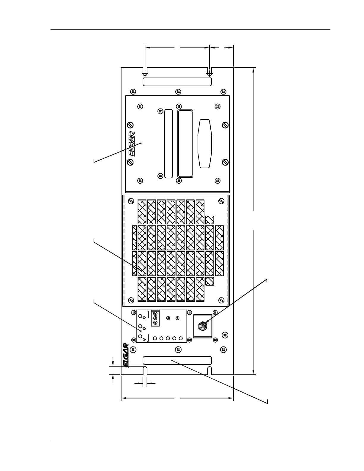
Installation
S
)
O
O
O
(4.000)
(1.485
DULE
VABLE BATTERY M
WARNING
REM
INACTIVE STOR AGE OF 30 DAYS O R M ORE
REMOVE BATTERIES BEFORE SHIPMENT OR
BATTERY MODULE
VABLE AIR FILTER
(19.00)
(INTAKE)
REM
PLAY PANEL
DI
ON
TEST
OUTPUT
AC INPUT
BATT
ON
GLOBAL UPS
GUPS 2400A-104
BATT
-AB -AC -BC
ALARM
SILENCE
LOAD
TEMP
TEST
AC INPUT
PUSHON/PULL OFF
AC INPUT CIRCUIT BRKR
4 x .50
4 x .25
(6.968)
4X HANDLE
Figure 2–1. GUPS 2400A–104 (Front View)
GUPS 2400A–104 Operation Manual 2-3
Page 12

Installation
AC OUTPUT
CONNECTOR
J8
DATA/ALARM
PORT
J4
J3
AC OUTP UT, 10A MAX
J2
CB1
J7
J6
AC OUTP UT, 15A MAX
TOTAL AC OUTPUT : 20.9A MAX
OUTPUT POWER
CIRCUIT BREAKER
J5
CB2
OUTPUT POWER
CIRCUIT BREAKER
DATA/ALARM PORT
CHASSIS
NO OPERATOR SERVICEABLE PARTS INSIDE.
REFER SERV IC ING T O QUAL IF IED PERSONNEL.
TO AVOID ELECTRICAL SHOCK, THE CHASSIS
MUST BE CONNECTED TO EARTH GROUND.
Revision: A
Date Code:
San Diego, CA
CAUTION:
115V, 1-Phase, 60Hz
2,400VA/1920W,Max
200/115V, 3-Phase, 370-430Hz
3-Wire Plus Ground; Neutral Not Used
159-232V, Max Phase-To-Phase
12.5A, Max At 159V
Ac Input:
Part No: 51523 32-01
Ac Output:
Serial No:
WARNING:
GND
GROUND STUD
AC INPU T
CONNECTOR
J1
AC INPUT
Figure 2–2. GUPS 2400A–104 (Rear View)
2-4 GUPS 2400A–104 Operation Manual
Page 13

Installation
1.75
.160
25.10
ELECTR OST ATI C SENSIT IVE EQUIPMEN T
SPECIAL HANDLING REQUIRED
REQUIRED
DANGER
COVER REMOVED
HIGH VO LTAGE I S
EXPOSED WHEN
CAUTION
2-MAN LIFT
CAUTION
.825
1.75
.65
16.90
15.60
1.730
BOTTOM EDGE OF
FRONT PANEL
.625
5 EQ SP @ 3.875 = 19.375
BOTTOM OF CHASSIS
12X PN LAC-032-2
6.920
TO TOP COVER
Figure 2–3. GUPS 2400A–104 Dimensions (Top, Side, and Front Views)
GUPS 2400A–104 Operation Manual 2-5
Page 14

Installation
2.6 Wire Gauge Selection
The following guidelines assist in determining the optimum cable specification for the user's
power applications. These guidelines are equally applicable to both DC and low frequency AC
(up to 450 Hz) power cabling. The same engineering rules apply whether going into or out of an
electrical device. Thus, this guide applies equally to the input cable and output cable for this
Elgar instrument and application loads.
Power cables must be able to safely carry maximum load current without overheating or causing
insulation destruction. It is important to everyday performance to minimize IR (voltage drop)
loss within the cable. These losses have a direct effect on the quality of power delivered to and
from instruments and corresponding loads.
When specifying wire gauge, the operating temperature needs to be considered. Wire gauge
current capability and insulation performance drops with the increased temperature developed
within a cable bundle and with increased environmental temperature. Thus, short cables with
generously derated gauge and insulation properties are recommended for power source
applications.
Avoid using published commercial utility wiring codes. These codes are designed for the
internal wiring of homes and buildings and accommodate the safety factors of wiring loss, heat,
breakdown insulation, aging, etc. However, these codes consider that up to 5% voltage drop is
acceptable.
Such a loss directly detracts from the quality performance specifications of this instrument.
Frequently, these codes do not consider bundles of wire within a cable arrangement.
In high performance applications, as in motor start-up and associated inrush/ transient currents,
additional consideration is required. The cable wire gauge must consider peak voltages and
currents which may be up to ten times the average values. An underrated wire gauge adds
losses which alter the inrush characteristics of the application and thus the expected
performance.
Table 2–2 identifies popular ratings for DC and AC power source cable wire gauges.
Column 1
Size
(AWG)
14 15 0.257 3.85
12 20 0.162 3.24
10 30 0.102 3.06
8 40 0.064 2.56
6 55 0.043 2.36
4 70 0.025 1.75
2 95 0.015 1.42
1/0 125 0.010 1.25
3/0 165 0.006 1.04
Column 2
Amperes
(Maximum)
Column 3
Ohms/100 Feet
(One Way)
Column 4
IR Drop/100 Feet
(Col. 2 x Col. 3)
Table 2–2. Recommended Wire Gauge Selection Guide
2-6 GUPS 2400A–104 Operation Manual
Page 15

Installation
The following notes apply to Table 2–2 and to the power cable definition:
1. The above figures are based upon insulated copper conductors at 25°C (77°F), two current
carrying conductors in the cable plus a safety (chassis) ground.
Columns 3 and 4 refer to "one way" ohms and IR drop of current carrying conductors
(e.g., a 50-foot cable contains 100 feet of current carrying conductor).
2. Determine which wire gauge for the application by knowing the expected peak load current
(I
), the maximum tolerated voltage loss (V
peak
) within the cable, and the one way cable
loss
length. The formula below determines which ohms/100 feet entry is required from Column
3. Read the corresponding wire gauge from Column 1.
(Column 3 value) = V
loss
/[I
x 0.02 x (cable length)]
peak
Where:
Column 3 value = Entry of the table above.
Cable length = One way cable length in feet.
V
= Maximum loss, in volts, permitted within cable.
loss
SPECIAL CASE:
Should the V
requirement be very loose, I
loss
may exceed the maximum amperes
peak
(Column 2). In this case, the correct wire gauge is selected directly from the first two
columns of the table.
EXAMPLE:
A 20 ampere (I
) circuit which may have a maximum 0.5 volt drop (V
peak
) along its
loss
15-foot cable (one way cable length) requires (by formula) a Column 3 resistance value
of 0.083. This corresponds to wire gauge size 8 AWG.
If the cable length was 10 feet, the Column 3 value would be 0.125 and the
corresponding wire gauge would be 10 AWG.
3. Aluminum wire is not recommended due to soft metal migration at the terminals which may
cause long term (on the order of years) poor connections and oxidation. If used, increase the
wire gauge by two sizes (e.g., specify 10 gauge aluminum instead of 14 gauge aluminum).
4. Derate the above wire gauge (use a heavier gauge) for higher environmental temperatures
since conductor resistance increases with temperature.
Temperature Current
°C
°F Capability
40 104 80%
GUPS 2400A–104 Operation Manual 2-7
Page 16

Installation
5. Derate the above wire gauge (use a heavier gauge) for an increased number of current carrying
conductors. This offsets the thermal rise of bundled conductors.
Number of Current
Conductors
3 to 6 80%
Above 6 70%
6. The preferred insulation material is application dependent. Elgar recommends any flame
retardant, heat resistant, moisture resistant thermoplastic insulation rated to a nominal 75°C
(167°F). Voltage breakdown must exceed the combined effects of:
• The rated output voltage;
• Transient voltages induced onto the conductors from any source;
• The differential voltage to other nearby conductors; and,
• Safety margins to accommodate degradations due to age, mechanical abrasion and
insulation migration caused by bending and temperature.
Capability
7. As frequency increases, the magnetic field of the current carrying conductors becomes more
significant in terms of adverse coupling to adjacent electrical circuits. Use twisted pairs to
help cancel these effects. Shielded twisted pairs are even better. Avoid close coupling with
nearby cables by using separate cable runs for high power and low power cables.
8. The above general values and recommendations should be reviewed, modified and
amended, as necessary, for each application. Cables should be marked with appropriate
safety WARNING decals as hazardous voltages may be present.
2-8 GUPS 2400A–104 Operation Manual
Page 17

SECTION 3
OPERATION
3.1
This section provides detailed information on the controls and indicators, input/output
connections, start-up and shutdown sequences, battery operation, and the RS-232 data
communications port.
3.2
All controls and indicators for the GUPS 2400A–104 are located on the front panel of the unit.
There are no operator adjustments inside the unit. Refer to Figure 3–1 for the location of the
controls and indicators listed below.
There are eight indicators and three pushbutton switches on the panel. In addition, there is an
input circuit breaker located below the control panel.
Introduction
Control and Indicator Panel
3.2.1 Indicators
AC INPUT. Three green LEDs that indicate the presence of line voltage at the AC input. The
indicators turn on when the line voltage is greater than 90V (phase voltage greater than 52V).
ON BATT. An amber LED that indicates the loss of AC input and operation from battery
power.
BATT. A three-color LED that indicates the condition of the battery. The LED is green under
normal operating conditions, amber when the battery is discharging or has low capacity while
charging, and red when the battery capacity is low and impending inverter shutdown is
approached.
LOAD. A three-color LED that indicates the amount of output load. The LED is green when the
load is less than 80% of maximum output, amber when the load is within 80% to 105%, and red
when the load exceeds 105% (indicating the inverter will shut down if the load is maintained).
TEMP. A two-color LED that indicates temperature condition within the GUPS. The LED is
green under normal operating conditions, and red when an over-temperature shutdown occurs.
GUPS 2400A–104 Operation Manual 3-1
Page 18

Operation
TEST. A two-color LED that indicates the results of the internal self-test. The LED blinks while
a self-test is in progress. When the test is complete, the LED turns green if the test is passed
and red it the test is failed.
3.2.2 Pushbutton Switches
OUTPUT ON. A momentary pushbutton switch on the front panel that alternately turns the
output power on and off.
TEST. A momentary push button switch on the front panel that initiates the internal self-test.
ALARM SILENCE. A momentary pushbutton switch on the front panel that silences the
audible alarm.
GUPS 2400A-1 04
GLOBAL UPS
-AB
-AC
AC INPUT
ON
BATT
BATT
OUTPUT
ON
LOAD
TEMP
TEST
TEST
ALARM
SILENCE
15
AC INPUT
PUSH-ON/PULL-OFF
-BC
Figure 3–1. GUPS 2400A–104 Control and Indicator Panel
3-2 GUPS 2400A–104 Operation Manual
Page 19

Operation
3.3
AC INPUT
The AC input breaker is located on the front panel below the Control and Indicator Panel.
It is turned ON by pushing in the actuator button, and it is turned OFF by pulling out the actuator
button.
AC OUTPUT
Two circuit breakers are present on the rear panel: one rated at 10A for protecting one set of
three AC output connectors; another rated at 15A for protecting the other set of three AC output
connectors. They are turned ON by pushing in the actuator buttons, and they are turned OFF by
pulling out the actuator buttons.
3.4
An audible alarm is sounded for the following alarm conditions: loss of AC input; low battery
voltage; over-temperature. If the audible alarm is silenced and an alarm condition is again
present, the audible alarm will again be sounded.
3.5
Circuit Breakers
Audible Alarm
Control Signals
The Data/Alarm Port provides an interface to remote alarms or a host computer. The control
signals provide annunciation of the mode of operation, control of the system shutdown, and RS232 data communications. The control signals of the Data/Alarm Port and their signal return
could be floated up to 80VPK above chassis ground.
AC FAIL
Normally-open relay contacts that close when the AC input is outside the allowed range for
voltage or phase unbalance.
LOW BATTERY
Normally-open relay contacts that close when the battery voltage approaches the shutdown
threshold for the inverter.
SHUTDOWN
Input to a relay coil whose contacts interface with the control circuits of the GUPS. Energizing
the relay with a DC voltage, 16.8-36VDC (1,070 ±10% coil resistance), will result in shutdown.
If SHUTDOWN is asserted while the AC input is present, the output relay will open and output
power will be turned off; the inverter and control circuits will continue to operate.
If SHUTDOWN is asserted while the AC input is not present and the inverter is running from the
battery, the output relay will open and output power will be turned off; the inverter and control
circuits will be shut down also. After shutdown, the OUTPUT ON switch must be manually
toggled to turn the output back on.
GUPS 2400A–104 Operation Manual 3-3
Page 20

Operation
RS-232 TRANSMIT/RECEIVE
RS-232 transmit and receive for data communications. Refer to Section 3.9 for more information
on RS-232 interface.
OUTPUT CURRENT
An AC voltage signal that is proportional to the AC output current. The output is 0.221V/A, or
4.6 VRMS at full load. This signal is transformer isolated from the other control signals.
3.6 Connectors
The GUPS 2400A–104 has cylindrical, metal-shell connectors with bayonet coupling for all
input/output connections of power and signal. All connectors are located on the rear panel.
Six output connectors are provided: one set of three protected with a 10A circuit breaker, and
another set of three protected with a 15A circuit breaker. See Table 3–1 for pin assignments.
Connector Pin Assignment
Connector J1,
AC INPUT
Connectors J2 – J7,
AC OUTPUT
Connector J8,
DATA/ALARM PORT
GROUND STUD #10-32 Stud: Earth Ground
Table 3–1. GUPS 2400A–104 Connector Pin Assignments
Pin A: Phase A
Pin B: Phase B
Pin C: Phase C
Pin D: Not used
Pin E: Chassis Ground
(Neutral not used)
Pin A: Neutral (internally connected to chassis)
Pin B: Line
Pin C: Chassis Ground
Pin A: AC FAIL normally-open relay contact
Pin B: LOW BATTERY normally-open relay contact
Pin C: SHUTDOWN input for remote shutdown
Pin D: RS-232 TRANSMIT signal (output)
Pin E: RS-232 RECEIVE signal (input)
Pin F: SIGNAL RETURN for signals on Pins A-E
Pin G: OUTPUT CURRENT sense signal
Pin H: Return for OUTPUT CURRENT sense signal
3-4 GUPS 2400A–104 Operation Manual
Page 21

Operation
3.7
To run the GUPS 2400A–104 from an AC input, perform the following steps:
1. Turn on the AC input circuit breaker located on the front panel.
2. Wait approximately 10 seconds for completion of the start-up routines. During this
3. After the start-up delay, the inverter will turn on (fan will be energized), but the output
4. To turn ON the output, press the OUTPUT ON switch. The output relay will close
If the AC input voltage exceeds the allowed range, the unit will draw power from the
5. To turn OFF the output, press the OUTPUT ON switch again; the switch has a
If the AC input voltage exceeds the allowed range while the output is turned off, the
Start-Up and Shutdown Sequences
time, the GUPS performs a self-test to assure proper functionality, and the rectifier
undergoes a soft-start so that current surges on the AC input are prevented.
will be off. Also, the charger will be on to charge the internal battery.
and connect the inverter to the load. The inverter will momentarily turn off prior to
closing of the output relay to prevent switching load current with the relay.
internal battery and continue to run until the battery is depleted. If the AC input
returns to the allowed range, and low battery shutdown of the inverter has not yet
occurred, the unit will again draw power from the AC input and also recharge the
battery with the battery charger.
alternating ON/OFF action. The inverter will momentarily turn off and the output
relay will open. The inverter will again turn on after the relay is open. The inverter is
turned off while the relay is opening to prevent switching load current with the relay.
unit will shut down; the inverter, charger, and all control circuits will be turned off.
3.8
Battery Operation
CAUTION!
If the battery module is not inserted when the unit is started, all front
panel LEDs will indicate RED, and the unit will not operate.
To run the GUPS 2400A–104 from battery when an AC input is not present or outside the
allowed operating range, perform the following:
1. The AC input circuit breaker located on the front panel could be either in the ON or
OFF positions.
2. To turn ON the output, press the OUTPUT ON switch. After a short delay, the output
relay will close and the inverter will start, supplying power to the load. The unit will
run until the battery is depleted. If the AC input returns to the allowed range, and the
AC input breaker is closed, power will be drawn from the AC input and the battery
charger will recharge the battery.
GUPS 2400A–104 Operation Manual 3-5
Page 22

Operation
3. To turn OFF the output, press the OUTPUT ON switch again to use the alternating
ON/OFF action of the switch. The unit will shut down (with no AC input present); the
inverter and all control circuits will turn off.
3.8.1 Battery Care and Handling
The battery used in the GUPS 2400A-104 requires proper storage and recharging to maintain
reliability.
During storage, the self-discharge of the battery results in a sulfate coating that builds up on the
plates. This coating reduces the effective surface area of the plates which reduces the available
backup time. Allowing the batteries to self-discharge for too long may result in recharging
problems or in battery degradation.
Storing the battery at low temperatures reduces the level of chemical activity, thus sulphation
takes longer to occur. Reasonable storage times at different temperatures are listed in
Table 3–2.
Storage Temperature Storage Time
0°C (32°F) 20 Months
10°C (50°F) 10 Months
20°C (68°F) 5 Months
40°C (104°F) 1½ Months
Table 3–2. Battery Storage Times
The batteries should be recharged for 72 hours after prolonged storage.
CAUTION!
Failure to recharge the batteries after the storage time may result in
permanent battery degradation.
3-6 GUPS 2400A–104 Operation Manual
Page 23

Operation
3.9
RS-232 Data Communications Port
The RS-232 data communications port provides an interface between a data terminal (or a
computer emulating a data terminal) and the GUPS 2400A–104. It allows transfer of information
such as parameter values, mode of operation, and alarm conditions.
3.9.1
Hardware Interface
Interface signals for communication to and from the GUPS 2400A-104 are provided via a
connector (PT02CE-12-8S) located on the rear panel of the unit. The RS-232 interface
connector is designated as J8, DATA/ALARM PORT. The J8 connector pin-out for the RS-232
interface is given in Table 3–3.
Pin Number Signal
D Transmit from the GUPS
E Receive to the GUPS
F Signal Ground
Table 3–3. RS-232 Connector Pin-Out
3.9.2 Software Interface
The RS-232 interface firmware in the GUPS 2400A-104 has the following communication
features:
•
Two sets of remote terminal software commands
•
Text data request commands, which are applicable for dumb terminal display of the
unit status. Text data request commands return both descriptive text and the data
values requested
•
Fast “data only” data request commands called the Elgar Terminal Interface (ETI), for
use by a program running on a host computer. The ETI commands return only the data
values that are requested
•
Data available via the RS-232 interface includes
•
AC Line Loss signal
•
AC Input voltage in floating point or hexadecimal
•
AC output voltage in floating point or hexadecimal
•
AC output current in floating point or hexadecimal
•
Battery/Charger DC voltage in floating point or hexadecimal
•
Impending shutdown annunciation
GUPS 2400A–104 Operation Manual 3-7
Page 24

Operation
3.9.3 RS-232 Protocol
The GUPS 2400A–104 RS-232 communications port protocol is given in Table 3–4.
Baud Rate 9600
Data Bits 8
Start Bits 1
Stop Bits 1
Parity None
Table 3–4. RS-232 Communications Port Protocol
3.9.4 Test Data Request Commands
The GUPS 2400A–104 RS-232 text data mode commands have been developed for a user
interface utilizing a dumb terminal interface. The text data mode commands provide formatted
responses that include both the name of data parameters and the measured values. Each of the
text data requests supported by the GUPS 2400A–104 is described below.
3.9.4.1 List Selection Menu
Enter a “space” (0x20) character to view the following menu:
k = Display calibration constants
l = ETI calibration
m = ETI A/D
n = ETI Float
s = Status registers
v = Display version
3-8 GUPS 2400A–104 Operation Manual
Page 25

Operation
3.9.4.2 Display Calibration Values
Enter a command ‘k’ (lowercase K) character to display the calibration constants for the A/D
converter algorithms values. For example:
Calibration Constants:
80 percent current: 32F8 // Output current in hexadecimal
105 percent current: 424B
150 percent current: 50E7
Minimum voltage band: 2000 // Output voltage in hexadecimal
Maximum voltage band: 2100
Battery 200 volts 0198 // Battery voltage in hexadecimal
Battery bad: 0240
Battery shutdown: 0268
AC line A-B scale factor: 31030 // AC input line voltage scale factors in decimal
AC line B-C scale factor: 31030
AC line C-A scale factor: 31030
Vout rdbk cal: 91.3 / / Output voltage readback calibration in
Vout rdbk dvm: 114.5 floating point format
3.9.4.3 Display Status Registers and A/D Values
Enter a command ‘s’ (lowercase S) character to display the two 16-bit status registers, along
with the A/D values of the AC input voltage, Output voltage, Output current, and Battery/Charger
voltage. For example:
Status word 1: 5540 // 16-bit status flags in hexadecimal
Status word 2: 0283
A/D Values: // A/D values in floating point and hexadecimal
Output Voltage: 115.0 2314
Output Current: 3.25 0028
Input Voltage A-B: 200.0 4E20
Input Voltage B-C: 200.0 4E20
Input Voltage C-A: 200.0 4E20
Battery Voltage: 190.00 0284
The status word formats are explained in Section 3.9.6.
3.9.4.4 Display Firmware Version Number
Enter a command ‘v’ (lowercase V) character to display the version number of the firmware.
For example:
Firmware version number: P/N 5152457-01, Rev 2.0
GUPS 2400A–104 Operation Manual 3-9
Page 26

Operation
3.9.5 Elgar Terminal Interface (ETI) Data Request Commands
The GUPS 2400A-104 RS-232 text data mode commands have been developed for use by a
program running on a host computer. The ETI mode data request commands provide formatted
responses of only the measured value data in a formatted form. Each of the ETI data request
commands supported by the GUPS 2400A-104 is described below.
3.9.5.1 Provide Calibration Values
Enter a command ‘l’ (lowercase L) character to obtain the calibration constants for the A/D
converter algorithms values. For example, this command will return the GUPS 2400A–104
calibration constants in the following order:
Output Current at 80% // current calibration in hexadecimal
Output Current at 105%
Output Current at 150%
Minimum Output Voltage // voltage calibration in hexadecimal
Maximum Output Voltage
Battery Good Voltage // battery voltage in hexadecimal
Battery Bad Voltage
Battery Shutdown Voltage
Output Voltage Measurement // scale factor in floating point
Output Voltage Measurement
3.9.5.2 Provide Status Words and Hexadecimal A/D Values
Enter a command ‘m’ (lowercase M) character to obtain the Status Words and hexadecimal A/D
calibration constants for the A/D converter algorithms values. For example, this command will
return the A/D values and the unit status in the following order:
Status word 1 // 16-bit status flags in hexadecimal
Status word 2
Output Voltage // A/D values in hexadecimal
Output Current
AC Input Voltage Line A-B
AC Input Voltage Line B-C
AC Input Voltage Line C-A
Battery/Charger Voltage
The status word formats are explained in Section 3.9.6.
3.9.5.3 Provide Status Words and Floating Point A/D Values
Enter a command ‘n’ (lowercase N) character to obtain the Status Words and floating point A/D
calibration constants for the A/D converter algorithms values.
This command will return the A/D values and the unit status as in the ‘m’ command, but the
voltages and currents will be returned in IEEE floating point format.
3-10 GUPS 2400A–104 Operation Manual
Page 27

Operation
3.9.6 Status Words
The status words may be used to examine the current state of the GUPS 2400A–104, but are
not meant to be used in applications that are time–critical such as AC line loss detection. The
“Line Loss Detected” message sent from the GUPS 2400A–104 (refer to Section 3.9.7), or the
AC Line Loss signal (relay contact closure) will have the quickest response time.
3.9.6.1 Status Word 1 Format
Table 3–5 provides the bit position information and definition of the data in Status Word 1.
Bit Name Definition
0
1
2
3
4
5
6
7
8
9
10
11
12
13
14
15
Over Temperature
Alarm Sense
Alarm Silence
Charger Status
Current Overload
Battery Switch
Test Mode
Inverter Status
Output Relay
Impending Shutdown
Rectifier Slow Start
Equalization Charge
Power Available
PWM Soft Start
Reserved —
Battery Slow Start
0 = Normal Operation
1 = Over Temperature
0 = Alarm Not Sensed
1 = Alarm Sensed
0 = Alarm Silence Not Enabled
1 = Alarm Silence Enabled
0 = Charger Not On
1 = Charger On
0 = Normal Operation
1 = Current Overload
0 = Battery Switch Not On
1 = Battery Switch On
0 = Normal Operation
1 = Test Mode
0 = Inverter Not On
1 = Inverter On
0 = Output Relay Open
1 = Output Relay Closed
0 = Greater then 1 minute
1 = Less then 1 minute
0 = Normal Operation
1 = Rectifier In Slow Start
0 = Equalization Charge Not On
1 = Equalization Charge On
0 = Power Not Available
1 = Power Available
0 = Normal Operation
1 = Unit In Soft Start Mode
0 = Normal Operation
1 = Battery Slow Start
Table 3–5. Status Word 1 Data Format
GUPS 2400A–104 Operation Manual 3-11
Page 28

Operation
3.9.6.2 Status Word 1 Status Bit Condition Definitions
The definitions of the conditions and usage of the bits in Status Word 1 are defined below.
Over Temperature (Status Word 1, Bit 0)
The Over Temperature status bit indicates that the thermostat internal to the GUPS 2400A-104
has exceeded its trip point. A binary value of 0 indicates normal operation, while a binary value
1 indicates that the thermostat sensor has exceeded its trip point value of 95 degrees Celsius.
Alarm Sense (Status Word 1, Bit 1)
The Alarm Sense bit indicates that an alarm condition is currently being detected by the unit.
A binary value of 0 indicates that no alarms are being sensed, while a binary value of 1
indicates that an alarm is being sensed.
Alarm Silence (Status Word 1, Bit 2)
The Alarm Silence bit reflects the setting of the front panel Alarm Silence button of the GUPS
2400A-104. A binary value of 0 indicates that the Alarm Silence is Not Enabled (when an alarm
condition is sensed the audible alarm will annunciate it), while a binary value of 1 indicates that
the Alarm Silence is Enabled (a subsequent change in the alarm condition will re-enable the
alarm).
Charger Status (Status Word 1, Bit 3)
The Charger Status bit reflects the condition of the charger enabled logic of the GUPS
2400A-104. A binary value of 0 indicates that the charger is not on, while a binary value of 1
indicates that the charger is on.
Current Overload (Status Word 1, Bit 4)
The Current Overload bit indicates that the unit has sensed a current overload of greater than
105% of the specified output current. A binary value of 0 indicates normal operation, while a
binary value of 1 indicates that the output current is greater than 105% of the specified current
output capability of the unit.
Battery Switch (Status Word 1, Bit 5)
The Battery Switch bit reflects the status of the SCR battery switch in the GUPS 2400A-104
which connects the battery to the internal DC bus. A binary value of 0 indicates that the battery
switch is not on, while a binary value of 1 indicates that the battery switch is on.
Test Mode (Status Word 1, Bit 6)
The Test Mode status bit indicates if the GUPS 2400A-104 is in test mode. A binary value of 0
indicates that the unit is in normal operating mode, while a binary value of 1 indicates that the
unit is in test mode (as commanded by the execute test mode button on the front panel of the
GUPS 2400A-104).
Inverter Status (Status Word 1, Bit 7)
The Inverter Status bit indicates the operating condition of the output inverter of the GUPS
2400A-104. A binary value of 0 indicates that the output inverter is not on, while a binary value
of 1 indicates that the inverter is on.
3-12 GUPS 2400A–104 Operation Manual
Page 29

Operation
Output Relay (Status Word 1, Bit 8)
The Output Relay status bit indicates the state of the units output relay. A binary value of 0
indicates that the units output relay is open, while a binary value of 1 indicates that the output
relay is closed.
Impending Shutdown (Status Word 1, Bit 9)
The Impending Shutdown status bit indicates the status of the battery of the unit. A binary value
of 0 indicates more than 1 minute of back-up time is available or that the battery voltage is
greater than 177 volts, while a binary value of 1 indicates that less then 1 minute of back-up
time is available or that the battery voltage that is less than 177 volts.
Rectifier Slow Start (Status Word 1, Bit 10)
The Rectifier Slow Start status bit indicates that the unit is in rectifier slow start mode. A binary
value of 0 indicates that the unit is in normal operating mode, while a binary value of 1 indicates
that the unit is in rectifier slow start mode.
Equalization Charge (Status Word 1, Bit 11)
The Equalization Charge status bit indicates that the unit is in equalization charge enable mode.
A binary value of 0 indicates that the unit is normal operating mode, while a binary value of 1
indicates that the unit is in equalization charge mode.
Power Available (Status Word 1, Bit 12)
The Power Available status bit indicates that power is available to the unit either from the AC
input or the battery. A binary value of 0 indicates that power is not available, while a binary
value of 1 indicates that power is available.
PWM Soft Start (Status Word 1, Bit 13)
The PWM Soft Start status bit indicates that the unit is in PWM soft start mode. A binary value
of 0 indicates that the unit is in normal operating mode, while a binary value of 1 indicates that
the unit is in soft start mode.
Status Word 1, Bit 14
Reserved
Battery Slow Start (Status Word 1, Bit 15)
The Battery Slow Start status bit indicates the unit is in battery slow start mode. A binary value
of 0 indicates that the unit is in normal operating mode, while a binary value of 1 indicates that
the unit is in battery slow start mode.
GUPS 2400A–104 Operation Manual 3-13
Page 30

Operation
3.9.6.3 Status Word 2 Format
Table 3–6 provides the bit position information and definition of the data in Status Word 2.
Bit Name Definition
0
1
2
3
4
5
6
7
8
9
10
11
12
13
Running on Battery
Reserved
Inverter Keypress
System Shutdown
Reserved —
Running on AC Line
150% Overload Sense
Float Timer Time-out
Wait to equalize
Pass/Fail System Self-Test
System Down
AC Input Line Out of Range
Delayed Event Flag
Reserved —
0 = Running on AC
1 = Running on battery
0 = No Keypress Pending
1 = Inverter Keypress Pending
0 = System Operating
1 = System Shutdown
0 = Running on Battery
1 = Running on AC Line
0 = Normal Operation
1 = 150% Overload Detected
0 = Not Float Charging
1 = Float Timer Time-out
0 = No Equalization Pending
1 = Waiting To Equalize
0 = Self Test Failed
1 = Self Test Passed
0 = System Operational
1 = System Is Shutting Down
0 = AC Input Line In Range
1 = AC Input Line Out of Range
0 = No Pending Delayed Events
1 = Delayed Event Pending
14
15
3-14 GUPS 2400A–104 Operation Manual
Reserved —
Improper Output Voltage
Table 3–6. Status Word 2 Data Format
0 = Output Normal
1 = Output Is Low
Page 31

Operation
3.9.6.4 Status Word 2 Status Bit Condition Definitions
The definitions of the conditions and usage of the bits in Status Word 2 are defined below.
Running on Battery (Status Word 2, Bit 0)
The Running on Battery status bit indicates that the unit is operating on batteries. A binary value
of 0 indicates that the unit is running on AC input, while a binary value of 1 indicates that the
unit is running on battery.
Status Word 2, Bit 1
Reserved.
Inverter Keypress (Status Word 2, Bit 2)
The Inverter Keypress status bit indicates that a front panel keypress has occurred. A binary
value of 0 indicates that no key presses are pending, while a binary value of 1 indicates that a
keypress has occurred.
System Shutdown (Status Word 2, Bit 3)
The System Shutdown status bit indicates that the system has been commanded to shut down,
and a system shutdown is in effect. A binary value of 0 indicates that the system is operating
(normal operating mode), while a binary value of 1 indicates that the unit is in system shutdown
mode.
Status Word 2, Bit 4
Reserved.
Running on AC Line (Status Word 2, Bit 5)
The Running on Line status bit indicates that the unit is operating on the AC input. A binary
value of 0 indicates that the unit is running on battery input, while a binary value of 1 indicates
that the unit is running on the AC input.
150% Overload Sense (Status Word 2, Bit 6)
The 150% Current Overload bit indicates that the unit has sensed a current overload of greater
than 150% of the specified output current. A binary value of 0 indicates normal operation, while
a binary value of 1 indicates that the output current is greater than 150% of the specified current
output capability of the unit.
Float Timer Time-out (Status Word 2, Bit 7)
The Float Timer Time-out status bit indicates the condition of the units float timer function.
A binary value of 0 indicates that the timer has not timed out, while a binary value of 1 indicates
that the unit’s float timer has timed-out.
Wait to Equalize (Status Word 2, Bit 8)
The Wait to Equalize status bit indicates if the unit is waiting to equalize the batteries. A binary
value of 0 indicates that the unit has no equalization pending, while a binary value of 1 indicates
that the unit is waiting to equalize the batteries.
GUPS 2400A–104 Operation Manual 3-15
Page 32

Operation
Pass/Fail System Self-Test (Status Word 2, Bit 9)
The Pass/Fail System Self-Test status bit indicates the results of the last run system self test.
A binary value of 1 indicates that the unit passed the last self-test, while a binary value of 0
indicates that the unit failed the last self-test.
System Down (Status Word 2, Bit 10)
The System Down status bit indicates that the unit is in shutdown mode. A binary value of 0
indicates that the unit is operational, while a binary value of 1 indicates that the system is in
shutdown mode.
AC Input Line (Status Word 2, Bit 11)
The AC Input Line status bit indicates the condition of the AC input line. A binary value of 0
indicates that the AC input line is within the specified input range, while a binary value of 1 is not
within the specified input range.
Delayed Event Flag (Status Word 2, Bit 12)
The Delayed Event Flag status bit indicates the status of pending delayed events. A binary
value of 0 indicates that the unit has no pending delayed events, while a binary value of 1
indicates that unit has at least one delayed event pending.
Status Word 2, Bit 13
Reserved.
Status Word 2, Bit 14
Reserved.
Improper Output Voltage (Status Word 2, Bit 15)
The Improper Output status bit indicates that the unit has sensed a sustained low voltage
condition on the output. A binary value of 0 indicates that the output is normal, while a binary
value of 1 indicates that the output voltage has dropped to less than 80 % of its nominal value.
3.9.7 AC Line Loss Signal
When the AC line is lost, the GUPS 2400A–104 will send the message “Line Loss Detected” out
the RS-232 port. Applications may use this as a trigger to take action on a host computer.
3-16 GUPS 2400A–104 Operation Manual
Page 33

SECTION 4
MAINTENANCE
4.1 Introduction
This section contains general information about maintenance of the GUPS 2400A-104. There
are no adjustments accessible to the user.
4.2
WARNING
Hazardous voltages are present when operating this equipment. Please
read the SAFETY NOTICE on page iv prior to installation, operation, or
maintenance.
Service Information
Questions concerning the operation, repair or service of this instrument should be directed to
the nearest Elgar representative or to the Elgar Service Department, Elgar Electronics
Corporation, 9250 Brown Deer Road, San Diego, CA 92121-2294. Include the model number
and serial number in any correspondence concerning this instrument. DO NOT return the unit to
the factory without prior authorization.
4.3
When ordering spare parts or repair parts, specify the part name, part number, component
value and rating, and the Elgar part number, if available.
If complete assemblies are required, contact the Elgar Service Department. When ordering,
specify the assembly part number as marked on the assembly and the unit model number,
GUPS 2400A-104.
4.4
The only maintenance required for this instrument is to periodically remove and clean or replace
the front panel fan filter.
The amount of time between cleaning is dependent on the environment in which the unit
is used. Dust and dirt accumulation in the air filter can cause restricted airflow and subsequent
overheating or reduced life on the internal components and batteries.
Spare and Repair Parts
Periodic Maintenance
GUPS 2400A–104 Operation Manual 4-1
Page 34

Maintenance
4.5 Troubleshooting
In the event that a problem arises during unit operation, refer to the guidelines listed in
Table 4–1 to assist in determining the cause and to repair the unit as quickly as possible.
Symptom Probable Cause Suggested Solution
No indicators are
illuminated.
All indicators are
illuminated red.
AC is not present on the
output.
The ON BATT indicator
is illuminated amber.
The TEMP indicator
is illuminated red.
The BATTERY indicator
is illuminated red.
The inverter transfers
to battery then quickly
shuts down.
The AC line voltage is not
present.
The battery module is
unplugged.
The output relay is not closed;
the output circuit breakers are
open.
The AC input is either below
169V or is above 232V.
The filter is clogged. Clean the filter, if required.
1) Low battery voltage or
2) a defective battery.
1) The batteries are
discharged; 2) the batteries
are sulfated; or 3) the output
relay is open.
Energize the input circuit breaker;
press the OUTPUT ON
pushbutton.
Open the input circuit breaker,
unplug the battery module then
re-insert the battery module into
the connector.
Press the OUTPUT ON
pushbutton; close the output
circuit breakers.
Ensure the AC line is within the
proper operating range.
1) Recharge the battery or
2) replace the battery, as
required.
1) Allow a 4-hour recharge of
the batteries; 2) allow a 72-hour
recharge of the batteries; or
3) press the OUTPUT ON
pushbutton, as required.
The LOAD indicator
is illuminated red.
The LOAD indicator
is not illuminated.
The TEST indicator
is blinking.
The TEST indicator
does
not blink when the TEST
pushbutton is pressed.
Table 4–1. GUPS 2400A-104 Troubleshooting Guide
4-2 GUPS 2400A–104 Operation Manual
There is an overload on the
output.
The output relay is open. Press the OUTPUT ON
The TEST pushbutton has
been pressed.
The output relay is closed. TEST will only be performed if the
Reduce the load.
pushbutton to close the output
relay.
Wait until the self-test is complete
before operating any other
controls.
relay is open.
 Loading...